Lionel Lines PowerMax Transformer User manual

71-1001-250
6/06
Lionel Lines
Ready-to-Run Train Set
Owner’s Manual
CAUTI N—ELECTRIC T Y
N T REC MMENDED F R CHILDREN UNDER EIGHT YEARS F AGE. AS WITH
ALL ELECTRIC PR DUCTS, PRECAUTI NS SH ULD BE BSERVED DURING
HANDLING AND USE T PREVENT ELECTRIC SH CK.
TRA SFORMER RATI GS—INPUT: 120 VAC; 60 HZ NLY.
AC UTPUT: 18 V; 30 VA

C ngratulati ns!
2
Congratulations on your purchase of the ready-to-run Lionel Lines Train Set! This set fea-
tures everything you need to get started—a PowerMax Transformer, a huge loop of easy-to-
assemble FasTrack track, a string of detailed cars, and a powerful Lionel locomotive.
Have fun growing with this complete train set! Start with the set components, then follow
your imagination into your own miniature world. Expand your railroad empire with addition-
al FasTrack track sections, enhance your layout with accessories, lengthen your consist with
extra cars, or operate a new locomotive at the head end of your train! Explore the possibilities
at your authorized Lionel dealer.
Use this Owner’s Manual to learn how to set up, operate, and maintain your train set for
years of reliable operation.
he transformer included with this set should be periodically
examined for conditions that may result in the risk of fire,
electric shock, or injury to persons (such as damage to the
output cord, blades, housing, or other parts). In the event that
such conditions exist, the transformer should not be used until
properly repaired.
Parents!
Lionel Lines Train Set Features
• Bright headlight
• Puffing smoke
• rainSounds sound system
• Forward-Neutral-Reverse operation
• Opening boxcar doors
• Operating derrick
• Operating couplers
The following Lionel marks may be used throughout this instruction manual and are protected under
law. All rights reserved.
Lione ®, TrainMaster®, Odyssey®, Rai Sounds®, CrewTa k™, TowerCom™, DynaChuff™,
StationSounds™, Pu mor®, E ectroCoup er™, Magne-Traction®, CAB-1®Remote Contro er,
PowerMaster®, Lione ZW®, ZW®, PowerHouse®, TMCC®, Lione vi e™, Lockon®, Wire ess Tether™,
LionMaster®, FatBoy™, American F yer®, TrainSounds™, PowerMax™
The name FasTrack®is used with permission from Pitsco, Inc.

Lionel Lines Train Set Inventory
• 4-4-2 Locomotive
• ender with rainSounds
• Boxcar
• Derrick
• Flatcar
• Square window caboose
• Playmat
• ractor and flatbed trailer
• Railroad signs
• Billboard
• Station platform
• Log load
• PowerMax ransformer with
accessory wire
• hree straight Fas rack track
sections
• Eight curved Fas rack track
sections
• One straight Fas rack terminal
track section
• Smoke fluid
• Replacement traction tire
• Owner’s Manual
3
Table f c ntents
Creating y ur lay ut
Operating your PowerMax Transformer safely 4
Building your Lionel layout 5
oining the FasTrack track sections 6
Wiring your PowerMax Transformer 7
Running y ur train
Running your train set 8
Adding smoke fluid to your locomotive’s smoke generator 9
Coupling 10
Operating your train with the PowerMax Transformer 10
Experiencing the features of the PowerMax Transformer 11-12
Reverse unit procedure 13
Setting up the derrick 14
Operating the derrick 14
TrainS unds s und system perati n
Operating the TrainSounds sound system 15
P werMax Transf rmer perati n
Powering your layout with the PowerMax Transformer 16
Maintaining and servicing y ur set
Lubricating your locomotive 17
Replacing your Square Window Caboose lamp 18
Replacing your locomotive’s traction tire 19
Replacing your locomotive’s headlamp 20
Replacing your Square Window Caboose lamp
Advanced connections: powering two isolated blocks with two transformers 21
Troubleshooting 22
Notes 23
Limited Warranty/Lionel Service 24

Operating your PowerMax Transformer safely
4
Your Lionel PowerMax Transformer is listed by Underwriter’s Laboratory Inc. and has been
carefully designed to ensure peak performance. When using electrical products, basic
safety precautions should be maintained.
Be sure to observe the following guidelines:
• Read the manual thoroughly before using this device.
• This device is not recommended for children under eight years of age.
• Parents should periodically inspect this product for potential hazards and, if necessary,
have them repaired by an authorized Lionel Service Center. In the event that such a condi-
tion exists, the transformer should not be used until it has been properly repaired.
• The PowerMax Transformer is intended to be used indoors. Do not use this device if water
is present. Serious or fatal injuries may result.
• Use the PowerMax Transformer only for its intended purpose.
• The PowerMax Transformer was meant to operate on 120-volt, 60-Hertz power. Do not con-
nect this product to any other power supply.
• Do not operate the PowerMax Transformer with a damaged cord, plug, or case.
• To avoid the risk of electrical shock, do not disassemble the unit. There are no user service-
able parts inside. If damaged, take this product to an authorized Lionel Service Center.
• Do not operate the PowerMax Transformer on your layout unattended. Obstructed acces-
sories or stalled trains may overheat, resulting in damage to your layout.
• Always unplug the PowerMax Transformer from the power source when not in use.
• Never insert objects into the ventilation slots on this product. Damage to sensitive
electronic components can result.
Creating y ur lay ut

5
Building your Lionel layout
Your set comes with eight curved, three straight, and one terminal section of track. Figure 1
provides some examples of layouts that you can build with these track sections.
By adding more FasTrack track sections, you can create an endless number of exciting
track arrangements for more fun, action, and variety. The railroad empire of your dreams can
quickly become a reality!
Creating y ur lay ut
Figure 1. Track layout ideas
Figure 2. Add-on Track Pack layouts
FasTrack Add-on Track Packs make it easy to expand your railroad. Each Track Pack
includes all the track sections you need to create a more advanced layout using the sections
included with this set. Refer to Figure 2 to explore the possibilities.
Inner Passing Loop Add-on Track Pack
6-12028
Figure 8 Add-on Track Pack
6-12030
uter Passing Loop Add-on Track Pack
6-12031
Siding Track Add-on Track Pack
6-12044
Track Packs available separately.

Joining the FasTrack track sections
FasTrack track sections join together easily. With interlocking roadbed sections and large
rail tabs, the track fits together securely so you always get good electrical contact. Take a
look at Figure 3 to see how to join the track sections.
1. Line up your two sections of track.
2. Insert the rail tabs into the openings at the ends of the corresponding
rails.
3. Press the sections together until the interlocking roadbed snaps into
place.
Figure 3. oining the track sections
Creating y ur lay ut
6
Rail tab

Wiring your PowerMax Transformer
7
Creating y ur lay ut
Connect your FasTrack terminal section to the PowerMax Transformer. Use the wires that
are already attached to the terminal section. Make sure that all connections are secure.
Loose connections can produce extremely high temperatures. For this reason, do not touch
the terminals or track connections during use. Also, do not locate scenery materials such as
lichen or ground foam near the terminals.
1. Feed the wires through the notch in the Fas rack terminal section. Refer to
Figure 4.
2. Loosen the red RACK thumbscrew terminal, then slide the spade-shaped
connector on the red wire into position. The thumbscrew post should be
positioned between the “blades” of the spade connector. Be sure that the blades are
touching the metal post. Tighten the thumbscrew to secure the connection.
3. Loosen the black RACK thumbscrew terminal, then slide the spade-
shaped connector on the black wire into position. Tighten the thumbscrew to
secure the connection. Be sure that the blades are touching the metal post. Tighten the
thumbscrew to secure the connection.
4. Plug the PowerMax ransformer into your wall outlet (120 volts).
As your layout expands, you may also make power connections with the stripped ends of
wires, placing no more than two wires on each terminal. For best performance on large
layouts, it is recommended that you use 16-gauge wire to connect your PowerMax
Transformer to the track. On larger layouts where several track connections are required, the
use of separate junctions/terminal strips (available at your local electronics store) is
recommended to prevent voltage drops.
To prevent the excessive build up of heat, be sure to select the proper wire gauge
for your layout. Track connections must be made with 18-gauge wire or heavier.
Larger layouts require a minimum of 16-gauge wire.
Caution!
U120/60z
A
0~18VAC
TRACK
Figure 4. Controller connections
FasTrack terminal section
Notch
Spade-shaped
connector

8
Running y ur train
Running your train set
With track p wer ff, place y ur train set n the track.
Refer to page 9 for information on coupling the cars.
33
3
3
2
2
4
4
P wer up y ur l c m tive with y ur transf rmer.
Your locomotive is designed to operate on 7-15 volts alternating cur-
rent. Virtually all Lionel and Lionel-compatible alternating-current transformers
are suitable.
Do not power your locomotive with direct-current (DC) transformers.
The locomotive was designed for use with alternating-current (AC)
transformers only.
M ve ‘em ut!
Get your locomotive moving. Your locomotive goes through a repeating pattern
of operations: forward, neutral, reverse, neutral, and so on. To sequence the reverse
unit, press the DIRECTION button on your transformer, or briefly bring the throttle
all the way back to the OFF position and then forward. Each press of the DIRECTION
button or interruption in track power causes the locomotive to advance to the next
operational state.
Adjust track voltage until your locomotive moves at your desired speed.
1
1
C nnect the drawbar between the l c m tive and tender.
See Figure 5.
If the smoke unit switch is in the ON position, add smoke fluid to your
locomotive’s stack to prevent damage to the smoke unit. Refer to
page 9 for additional information.
Caution!
ote!
Figure 5. Drawbar connection

Running y ur train
9
Adding smoke fluid to your locomotive’s smoke generator
Your locomotive is equipped with a smoke generator that produces safe, clean white smoke
during operation if the smoke unit switch is in the ON position. Refer to Figure 8 on
page 13 for the location of the switch.
The smoke generator requires the periodic addition of Lionel smoke fluid in order to function.
A small bottle of smoke fluid is included with this set. Press down and unscrew the cap. Pierce the
tip on the nozzle. Add about four drops of fluid directly into the locomotive’s stack. Smoke pro-
duction commences momentarily. It will start faster if you run your locomotive at higher speeds.
When smoke production decreases, add more fluid (about four drops). An idle locomotive will
not smoke.
Smoke production is greater at higher voltages and when the locomotive is pulling a heavy
load or a long consist.
Caution! When the smoke unit switch is in the ON position, always keep a small amount
of smoke fluid in the locomotive’s smoke generator; the generator’s element
can become damaged if operated without smoke fluid. This is particularly true
if your locomotive sits in neutral for an extended period of time without smoke
fluid in the generator.
If you prefer to operate the locomotive without smoke or you do not want to add
smoke fluid, slide the smoke unit switch to the OFF position.
ote!

10
Operating your trains with the PowerMax Transformer
You’re clear for departure! Move the throttle control handle forward to increase power to
the track. The farther forward you push the handle, the faster your train will go.
Quickly shutting off or throwing the throttle all the way forward will not result in
an instant change in track voltage.
When operating in the conventional (non-Command) environment, remember that the
greater the load on the engine (adding more cars for the engine to pull, for example), the far-
ther forward the handle must be pushed before it will operate the locomotive.
ote!
Running y ur train
Coupling
When coupling your cars, at least one of the mating couplers must be open as shown at the left
in Figure 6. Press down on the lock release to open the coupler, then push the cars toward
each other until they lock together.
Keep in mind that it’s easier to couple cars on a straight stretch of track.
Lock release
Figure 6. Coupler operation
ote!

ote!
ote!
Running y ur train
11
Experiencing the features of the PowerMax Transformer
Refer to Figure 7 on page 12 for the location of the Transformer features listed in this sec-
tion.
THROTTLE
Push the throttle forward to increase track power. The markings on the throttle approxi-
mate the percentage of full power. For more realism, push the throttle slowly to gradually
increase or decrease the speed of the locomotive. Slowing or stopping the locomotive with the
throttle instead of the DIRECTION button will allow you to continue in the same direction
when you increase the throttle again. To achieve this effect, reduce the throttle to the point
that the locomotive stops moving, don’t completely turn off the throttle. That way, your train
won’t sequence into neutral.
POWER-ON INDICATOR
The green light will remain on during normal operation. The green light will begin to
flash if you exceed the power limit of the Transformer. The unit will allow you to momentarily
exceed the power limit, but power will be gradually reduced until the problem is corrected.
This safety feature replaces the circuit breaker. The benefit is that the Transformer will not
instantly turn off.
DIRECTION
The DIRECTION control button interrupts track power to activate the reverse unit in loco-
motives with forward-neutral-reverse operation.
When the DIRECTION button is presssed, track power is interrupted instantaneously.
Track power is restored gradually when the DIRECTION button is released.
WHISTLE/HORN
The WHISTLE/HORN button will activate Lionel sound-equipped locomotives, including
those equipped with the RailSounds sound system. The sound will continue until the button is
released. No external sound activation buttons are needed.
BELL
The BELL button will activate all RailSounds bells. Press the BELL button to begin the
sounds; press the button again to turn off the ringing.
Do not activate horns, whistles, or bells on RailSounds-equipped locomotives until
track power has been turned on for a few moments, or a continuous horn/whistle or
bell sound may occur. To correct this problem, simply turn off the PowerMax
Transformer, then turn it back on.
The PowerMax Transformer may cause random whistles in the Lionel Mighty
Sounds of SteamTM tenders with a three-pin connector. We recommend that you a
purchase a RailSounds-equipped tender to solve this problem.
ote!

12
Whistle/Horn
Activates the whistle or horn sound
effect in your Lionel locomotives. Press
WHISTLE/H RN to begin the sound;
release the button to end it.
Bell
Starts or stops the tolling bell in any
RailSounds or TrainSounds-equipped
locomotive. Press BELL to begin the
sound, again to stop it.
Direction
Press the DIRECTI N button to go forward
or reverse, or to place the locomotive in
“neutral” (no movement, headlight is on).
Throttle
Controls your locomotive’s speed. Throw the throt-
tle forward to increase locomotive speed, back-
ward to slow it down.
Power-on indicator
The green light
illuminates when the
PowerMax is on.
Figure 7. Transformer features
Running y ur train
Experiencing the features of the PowerMax Transformer (continued)

Running y ur train
Reverse unit procedure
The electronic reverse unit inside your Lionel locomotive acts like the transmission in a car.
When you apply power to the track, the locomotive moves in the direction specified by the
reverse unit—or it sits in neutral, awaiting another power interruption. Power interruptions
are the signal that tells the reverse unit to sequence to the next operational state.
To interrupt power and sequence the locomotive’s reverse unit, press the direction control
button or briefly bring the throttle lever all the way back to the OFF position. Refer to Figure 9
for the location of these controls. The reverse unit alternates between three states: forward,
neutral, and reverse.
Also, the locomotive can be “locked” into a certain mode of operation by throwing the
reverse unit switch located on the underside of the frame (see Figure 8). When the switch is
thrown to the OFF position (towards the rear of the locomotive), the locomotive will be locked
in the next mode of operation in the sequence. To lock your locomotive into a specific opera-
tional state, sequence the locomotive into the desired state and reduce track power without
completely powering down the locomotive,
then throw the switch to the OFF position.
The DIRECTION button will then have no
affect on the direction of the locomotive. If
you would like to resume forward-neutral-
reverse operation, simply throw the reverse
unit switch back to the ON position.
Additionally, this reverse unit has a “power-
up reset” feature. If the locomotive sits with-
out power for a short period of time, the
reverse unit will automatically reset and start
in the forward direction when the trans-
former is turned on or “powered up,” regard-
less of the reverse unit switch position. If the
switch is in the OFF position, the locomotive
will start in the forward direction and be
“locked” there.
Reverse unit
N/ FF switch
Smoke unit
N/ FF switch
(see page 10)
Figure 8. Switch location
Figure 9. Direction control button location
Direction control button
Whistle control button
Bell control button
Throttle
FF
N
FF
N
13
Running y ur train
14
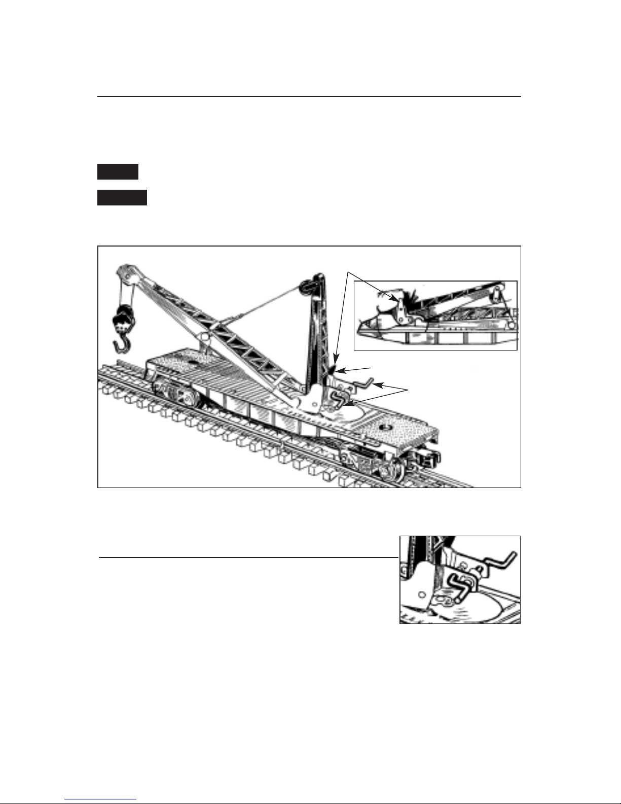
Setting up the derrick
Your Derrick car is packed with its mast folded down. To prepare the car for use, simply raise
the mast until it snaps into place in its vertical position. Refer to Figure 10. Also, check that
the lines are properly threaded through the pulleys.
To fold down the mast, pull the mast lock away from the derrick.
Be sure that the derrick clears the objects on your layout, including trains and
scenery. Also, raise the hook and the boom to avoid tangling the lines and drag-
ging the hook.
Caution!
ote!
Figure 10. Locking the derrick into position
Mast Lock
Mast
Boom
Cranks
Pull to disengage
Operating the derrick
Your derrick is operated by two hand cranks. Refer to Figure 11.
Use crank #1 to raise and lower the boom. Use crank #2 to control
the block and tackle.
Figure 11. Crank locations
2
1

15
TrainS unds s und system perati n
ote!
Operating the TrainSounds sound system
Your TrainSounds Tender was designed to operate at approximately 6 to 18 volts (AC).
When you power up the lovomoyibr on the track, you will hear the sounds of the idling
steam locomotive. The chuffing intensity will increase proportionally with the locomotive’s
speed.
Always operate the TrainSounds Tender with a lighted locomotive, an illuminated
car, or lighted track bumpers. This power draw will prevent the whistle from sound-
ing erratically.
Whistle
Press the WHIS LE button on your transformer to sound the whistle. The sound will play for as long
as you hold the button.
Brake squeal
To activate the sound of squealing brakes, operate your locomotive at a rapid rate of speed for
at least ten seconds, and then throttle down to a lower speed. The brake sounds will discontin-
ue automatically after a few moments.
If you are unable to activate the brake sounds, your locomotive’s speed may be too
low. Increase the speed of the locomotive, operate for at least ten seconds, and then
reduce the throttle by half.
Crew dialogue
When the car is not in motion, you may activate random crew dialogue using the WHISTLE
button on your controller.
The car must be powered up on the track and not in motion (in neutral) for the
dialogue to play. Do not turn off track power.
ote!
ote!
If you activate multiple “stand by” dialogues during the first 35 seconds, the length
of time before the “clear for departure” dialogue becomes 35 seconds, plus the
length of the dialogue.
Press the WHISTLE button Dialogue
Stop/Power-up to about 35 seconds “Stand by” dialogue
After 35 seconds “Clear for departure” dialogue
After 60 seconds Random, automatic crew dialogue
ote!

P werMax Transf rmer perati n
16
Powering your layout with the PowerMax Transformer
Your PowerMax Transformer provides a total output of 1.8 amps. Also, available voltage
depends on how much load is on the output. Generally, track voltage is 0-16 volts (AC).
You may momentarily approach or exceed the 1.8 amp limit of the PowerMax Transformer
when pulling illuminated cars, or fighting over grades with heavy loads. When you reach 1.8
amps, the green light on the Transformer will begin to flash. This indicates that the
Transformer is in “fold-back mode.” In fold-back mode, the Transformer is automatically
reducing, or folding back, power. This gradual reduction in power provides interruption-free
power while bringing the amperage back down to a safe level. If this condition lasts for more
than 30 seconds, the Transformer will shut off the power to the track and the green light will
continue to flash. Move the throttle to the off position to reset the Transformer and return to
normal operation.

17
Maintaining and servicing y ur set
Figure 12. Lubrication points
Lubricating your locomotive
Help your steam locomotive lead a long and productive life on your railroad by maintain-
ing it properly.
We recommend that you purchase a Lionel Lubrication and Maintenance Kit (6-62927),
available from your Lionel dealer. Two basic rules to keep in mind: never over-lubricate (a
small amount will do) and avoid getting grease or oil on the locomotive’s wheels, contact
rollers, or your track.
You’ll know your locomotive requires lubrication when visual inspection reveals dryness on
the parts indicated in Figure 12. Remove accumulated dirt and dust before lubricating, and
always lubricate any locomotive emerging from prolonged storage.
Lubricate axle ends
with Lionel oil
sparingly Lubricate gears with
Lionel grease sparingly Lubricate axle ends
with Lionel oil sparingly

18
Maintaining and servicing y ur set
Window
tab
Window shell
End frame tab
End frame
tab
Hinge
Lamp no. 600-8352-311
Replacing your Square Window Caboose lamp
Figure 13. Caboose lamp replacement
During the course of normal operations, the lamp inside your caboose may require
replacement. Follow these steps and refer to Figure 13.
1. Lift off the roof from the window shell and body.
2. Pull out the end frame tab from the slot formed by the caboose body and roof. The end
frames are hinged at the platform to swing outward, away from the body.
3. Remove the window shell. To remove the window shell, carefully bend the sides of the
caboose outward while pulling up on the window shell until the tabs are released from the
windows.
4. Pull the lamp straight up and out of the socket. Replace it with Lionel lamp no. 600-8352-311,
available at your authorized Lionel Service Center or Lionel Service.
5. Lower the window shell back into the body, making sure that the tabs snap into the win-
dows.
6. Reposition the roof above the window shell and body, fit the tabs on the end frames into
the corresponding slots in the body, and press down the roof to secure the end frame tabs.

Maintaining and servicing y ur set
19
Replacing your locomotive’s traction tire
One of the locomotive’s drive wheels is fitted with a rubber traction tire to enhance tractive
effort, allowing your locomotive to pull many cars at once.
To replace the traction tire, simply unscrew the drive rod screw from the wheel using a
3/16” nut driver. Refer to Figure 14. Remove the old traction tire from under the drive rod and
slip on the replacement, Lionel part no. 600-0242-206. Replace the spacer, retighten the drive
rod screw, and you’r e ready to pull that long freight back to the yard.
Figure 14. Traction tire replacement
Lionel part no. 600-0242-206
Spacer
Drive rod screw

Maintaining and servicing y ur set
20
Linkage rods
Front truck
screws
Smoke unit
lug wire
Smoke unit
Lionel part no.
600-0161-300
Your locomotive lights the way with its operating headlight. During the course of normal
operations, the lamp may require replacement. Refer to Figure 15 as you replace the
lamp.
1. Remove the two front truck screws and carefully slide the front truck assembly off the link-
age rods.
2. Lift the smoke unit out far enough from the cab to allow lamp extraction.
3. Pull the lamp straight out and replace it with Lionel part no. 600-0161-300, available from
your nearest authorized Lionel Service Center or from Lionel Service. Be careful not to twist
the lamp, or it may break.
4. Reinstall the smoke unit, making sure that the smoke stack lines up with the cab top opening.
5. Reassemble the front truck, making sure that the linkage rods go into the holes in the
front truck. The lug wire from the smoke unit must be reinserted through the slot in the
front truck assembly and secured under one of the two front screws. Tighten the screws
firmly, but do not over-tighten them.
Replacing your locomotive’s headlamp
Figure 15. Headlight replacement
Table of contents


