Ecotop Spacewalker I 06604 User manual

Order N° 06604
ATTENTION !
Ce modèle à construire n’est pas un jouet, il
ne convient pas aux enfants de moins de 14 ans.
Une mauvaise utilisation de ce matériel peut
provoquer des dommages matériels ou corporels.
Vous êtes pleinement responsable
lorsque vous utilisez votre modèle.
Volez à une distance de sécurité des zones
habitées.
Soyez sûr que personne n’émet sur la même
fréquence que vous.
CAUTION !
This model construction kit is not a toy and is not
suitable for children under the age of 14.
Incorrect use of this material could cause material
damage ou personal injury.
You are fully responsible for your actions when you
use this model.
Fly at a safe distance from occupied zones.
Be sure that no one else is using the same
frequency as you.
Distribué par / Distributed by:
TOPMODEL S.A.S.
Le jardin d’entreprises de SOLOGNE - F-41300 SELLES SAINT DENIS - www.topmodel.fr
©TOPMODEL 2011
Caractéristiques techniques/Technical data:
Envergure/wingspan: 2,10m
Longueur/length: 1,48m
Poids/TO weight: 5,0/5,4kg
Surface/wing area: 67,7dm2
Profil/airfoil: NACA 2414
Equipements recommandés/Recommended equipments:
Moteur/motor: DLE 30 + pot/muffler #06647737
Hélice/prop: MENZ 2-bladed 18x10”
Cône/spinner: ECOTOP alu Ø76mm #066ASP76
Radio/RC set: Récepteur/receiver: JETI Duplex R10
Ailerons: 2 servos HITEC HS-485HB
Profondeur/Elevator: 2 servos HITEC HS-485HB
Direction/Rudder: 1 servo HITEC HS-485HB
Volets/Flaps: 2 servos HITEC HS-485HB
Gaz/Throttle: 1 servo HITEC HS-311
Régulateur/Regulator: 2 XPower SVR3-5V + 2 connecteurs SVR pour/for 3S #099SVRC3S
Accu Rx/Rx pack: 1 pack Li-Po HOT-LIPS 11,1v 1000mAh
Accu allumage/Ignition bat: 1 pack Li-Po HOT-LIPS 11,1v 1000mAh
1 Kill Switch pour/for DLE #142KS
1 Mini tachy/tacho pour/for DLE #142MT
Distribué par / Distributed by:
p
/
y
TOPMODEL
S.A.S.
L
Trainer essence semi-maquette
Semi-scale gas trainer
SpacewalkerI

2
RETENDRE L’ENTOILAGE
1) Déballez doucement en prenant soin de ne pas endommager une
partie du kit. Déballez toutes les pièces de leur emballage plastique pour
inspection.
Avant de commencer tout montage ou de poser tout auto-collant, il
est très important de retendre l’entoilage déjà appliqué. A cause du
transport, de la chaleur et de l’humidité qui varient beaucoup suivant les
différents climats, l’entoilage peut se détendre et se “rider” au soleil. Si
vous prenez le temps de retendre l’entoilage, vous serez récompensé par
un modèle qui restera magnifique dans le temps.
2) En utilisant un fer à soler et un chiffon doux, “repassez” délicatement
et “suivez” en appliquant le film avec le chiffon. Si des bulles apparaissent,
votre fer est peut être trop chaud. Réduire la température et travaillez
doucement et patiemment.
3) Si les bulles persistent, piquer les bulles à l’aide d’une aiguille pour
évacuer l’air emprisonné et chauffer de nouveau.
4) Utilisez le décapeur thermique avec beaucoup de précaution. Faire
attention de ne pas chauffer au même endroit trop longtemps. Cela
pourrait trop rétracter les bords et laisser un espace découvrant le bois
aux jointures des différentes couleurs. Les filets sont particulièrement
vulnérables à la surchauffe.
5) Votre modèle est entoilé avec de l’Oracover® blanc N°10 et rouge Ferrari
N°23.
MERCI
d’avoir choisi l’avion trainer semi-maquette SPACEWALKER I!
Nous avons fait un grand effort en dessinant et construisant cet avion pour qu’il soit le meilleur modèle que vous ayez jamais construit et fait voler.
Nous vous fournissons un kit avec la plus haute qualité et les meilleures performances possibles.
Nous vous souhaitons un grand succès en assemblant et en faisant évoluer votre nouveau
SPACEWALKER I ECOTOP.
Le SPACEWALKER grandeur est un avion de construction amateur Américain construit a de nombreux exemplaires. Nous avons choisi de reproduire la version monoplace.
Bien que ressemblant à un avion réel, cet avion est le trainer idéal pour s’entrainer au pilotage. Les qualités de vol à basse vitesse sont excellentes et grâce à ses volets puissants,
les atterrissages sont facilités. C’est aussi la cellule idéale pour se familiariser avec les moteurs essence. Le kit est parfaitement préparé pour recevoir un moteur DLE 30 (ou DLE
20). Le tableau de bord fonctionnel permet de regrouper tous les éléments de contrôle et de commande du moteur. Ce mode de propulsion économique et fiable est idéal pour
emmagasiner les heures de vol sans se ruiner et en prenant beaucoup de plaisir.
IMPORTANT:Merci de bien vouloir lire et étudier cette notice de montage avant de commencer l’assemblage. Faire l’inventaire des pièces à l’aide de la nomenclature
pour contrôler qu’il n’y a pas de manquant ou d’imperfection.
Merci de contacter immédiatement TOPMODEL si vous constatez une pièce manquante ou une pièce endommagée.
GARANTIE: Il est important de notifier à TOPMODEL tous dommages ou problèmes avec ce modèle dans les 7 jours suivant la réception du kit pour bénéficier de la
garantie. En cas de retour du modèle, le client est responsable du transport et le port retour est à sa charge. En cas de défaut, la pièce sera échangée ou remplacée une fois
que celle-ci sera réceptionnée par TOPMODEL pour expertise (transport à la charge du propriétaire). En cas de problème, n’hésitez pas à contacter TOPMODEL.
TOPMODEL ne peut pas contrôler la dextérité du modéliste et ne peut pas influencer le constructeur durant l’assemblage ou l’utilisation de ce modèle radio-commandé. Aussi,
nous ne pouvons, en aucun cas, être tenus responsables des dégâts matériels, accidents corporels ou décès pouvant être causés par ce modèle réduit.
L’acheteur/utilisateur accepte toutes les responsabilités en cas de problèmes structurels ou mécaniques.
POUR ASSEMBLER CE KIT
Pour assembler ce kit, vous aurez besoin des produits énumérés ci-dessous:
■ COLLES: Cyano fluide et épaisse, époxy 30mn et 5mn, colle silicone.
■ OUTILS: Couteau de modéliste, tournevis cruciforme (petit et moyen), pince à bec fin, pince coupante, ciseaux, ruban adhésif, ruban adhésif de
masquage, ruban adhésif double-faces, perçeuse (foret Ø0,6-1,8-3 et 3,5mm), papier verre, règle, feutre, clips, alcool, fer à souder, chiffon.

3
RE-SHRINKING THE COVERING
1) Open you kit slowly and take care not to damage any parts of the kit.
Remove all parts from their plastic protective bags for inspection. Before
doing any assembly or installation of any decals, it is very important to
re-shrink or re-tighten the already applied covering. Due to the shipping
process, heat and humidity changes from different climates, the covering
may become lose and wrinkle in the sun. If you take the time to re-tighten
the covering, you’ll be rewarded with a long lasting beautifully covered
model.
2) Using your covering iron with a soft sock, gently apply pressure and rub
in the covering. If any bubbles occur, your iron may be too hot.
Reduce heat and work slowly.
3) If bubbles persist, use a small pin to punch holes in the bubble to
relieve trapped air and reheat.
4) Use your heat gun with extreme caution. Take care not to apply too
much heat to one area for long periods of time. This may cause the trim
colors to over shrink and pull away leaving sightly gaps on the color lines.
The trim stripes are especially vulnerable to over shrinking.
5) Your model is covered with Oracover® white #10 and Ferrari red #23.
THANK YOU for your purchase of the ECOTOP semi-scale ARF trainer
SPACEWALKER I
!
We made a main effort while drawing and building this airplane so that it is the best model one than you ever built and fly.
We provide you a kit with the highest quality and the best possible performances.
We wish you a great success while assembling and flying your new
SPACEWALKER I ECOTOP
.
The full size
SPACEWALKER
is an American experimental airplane built to many specimens. We chose to reproduce the single-seat version.
Although it looks like a real plane, this airplane is the ideal trainer. Low speed flying capabilities are excellent and thanks to its powerful flaps, the landings are easy to
complete. It is also the perfect airframe to familiarize itself with the gas engines. The kit is perfectly prepared for the installation of a DLE 30 (or DLE 20). The functional
instrument panel makes it possible to gather all the elements of control and monitoring of the engine. This economic and reliable power mode is ideal to log many hours of
flight without spending a lot and by taking much pleasure.
IMPORTANT: Please take a few moments to read this instruction manual before beginning assembly. Do an inventory of the parts using the parts list, to control that
there is no lack or imperfection. Thank you to contact TOPMODEL immediately, if you note a missing part or a damaged part.
WARRANTY: It is important to notify to TOPMODEL all damage or problems with this model within 7 days following the reception of the kit to be able to benefit the
warranty. In the event of return of the model, the customer is responsible for transport and return shipping cost is at his expenses. In the event of defect, the part will be
exchanged or replaced once this one will be delivered to TOPMODEL for expertise (transport on your cost). In the event of problem, do not hesitate to contact TOPMODEL.
TOPMODEL cannot control the dexterity of the modeler and cannot influence the builder during the assembly or the use of this radiocontrolled model, thus TOPMODEL will in
no way accept or assume responsability or liability for damages resulting from the use of this user assembled product.
The purchaser/user accepts all the responsibilities in the event of structural or mechanical problems.
TO ASSEMBLE THIS KIT
To assemble this kit, you’ll need the items listed below:
■ ADHESIVE: Cyanoacrylate thin and thick, epoxy 30’ and 5’ adhesives, silicon adhesive.
■ TOOLS: Knife (X-acto), Phillips screw driver (small and medium), needle tip pliers, pliers, scissors, scotch tape, masking tape, double sticking
tape, drill (with 0,6-1,8-3 and 3,5mm bits), sanding paper, ruler, ball point pen, clips, alcohol, soldering iron, piece of cloth or rags.

4

5
CONTENU DU KIT
KIT CONTENT
SpacewalkerI
PIECES TRINGLERIE AILERONS
(A) Aile ................................................... (Gauche/Droit).. 1
(B) Aileron.............................................. (Gauche/Droit).. 1
(C) Charnière bâton........................................................ 12
(D) Quick-link aileron (fileté aux extrémités) .................... 2
(E) Chape (métal)............................................................. 4
(F) Ecrou 4-40.................................................................. 4
(G) Vis M3x40mm ............................................................. 2
(H) Rondelle (aluminium).................................................. 4
(I) Ecrou M3..................................................................... 2
(J) Tête de guignol (plastique) ........................................ 2
PIECES TRINGLERIE VOLETS
(A) Volet................................................. (Gauche/Droit).. 1
(B) Charnière bâton........................................................ 10
(C) Quick-link aileron (fileté aux extrémités) .................... 2
(D) Chape (métal)............................................................. 4
(E) Ecrou 4-40.................................................................. 4
(F) Vis M3x40mm ............................................................. 2
(G) Rondelle (aluminium).................................................. 4
(H) Ecrou M3..................................................................... 2
(I) Tête de guignol (plastique) ........................................ 2
PIECES AILE
(A) Clé d’aile Ø23x650mm (aluminium) ......................... . 1
(B) Vis papillon M4x30mm................................................ 2
PIECES EMPENNAGE HORIZONTAL
(A) Empennage horizontal.............................................. . 1
(B) Volet de profondeur............................(droit/gauche) 2
(E) Charnière bâton.......................................................... 8
PIECES TRINGLERIE PROFONDEUR
(A) Tringlerie profondeur (L=75mm)............................. . 1
(B) Tringlerie profondeur (L=135mm)........................... . 1
(C) Chape métal.................................................................... 4
(D) Ecrou 4-40..................................................................... 4
(E) Guignol (base plastique)......................................2 sets
(F) Tête de guignol (plastique) ........................................ 2
(G) Vis 2x16mm.................................................................... 6
PIECES EMPENNAGE VERTICAL
(A) Empennage vertical .................................................. . 1
(B) Volet de dérive............................................................ 1
(E) Charnière bâton.......................................................... 5
PIECES TRINGLERIE DIRECTION
(A) Câble aller-retour...................................................... . 1
(B) Queue de chape (fileté).............................................. 4
(C) Chape (métal)............................................................. 4
(D) Ecrou 4-40.................................................................. 4
(E) Tube cuivre ................................................................. 4
(F) Guignol (base plastique)......................................2 sets
(G) Tête de guignol (plastique) ........................................ 2
(H) Vis 2x16mm ................................................................... 3
(I) Ecrou M2..................................................................... 3
(J) Tube guide (plastique)................................................ 2
PIECES DES HAUBANS DE STAB.
(A) Hauban (jonc carbone Ø2,5x185mm)...................... . 2
(B) Hauban (jonc carbone Ø2,5x197mm)...................... . 2
(C) Hauban (jonc carbone Ø2,5x228mm)...................... . 2
(D) Hauban (jonc carbone Ø2,5x236mm)...................... . 2
(E) Ferrure...................................................................... 16
(F) Vis M3x16mm ............................................................. 5
(G) Ecrou M3..................................................................... 5
(H) Vis à bois 2,6x10mm.................................................. 4
PIECES MONTAGE MOTEUR (DLE 20)
(A) Support moteur (avec écrous prisonniers M4)................... . 1
(B) Vis Chc M4x30mm..................................................... . 4
(C) Vis M5x20mm ........................................................... . 4
(D) Bâti moteur (plastique)............................................. . 1
PIECES MONTAGE MOTEUR (DLE 30)
(A) Bâti moteur (bois dur 4mm)..................................... . 5
(B) Tige filetée M5x40mm............................................... . 4
ENGINE MOUNTING PARTS (DLE 30)
(A) Engine mount (4mm hard wood)................................ 5
(B) M5x40mm threaded rod............................................. 4
PIECES COMMANDE MOTEUR
(A) Support servo (CTP 3mm) ................................. . 1 set
(B) Tringlerie des gaz (L=180mm)................................ . 1
(C) Tringlerie du starter (L=240mm) ............................ . 1
(D) Chape à rotule .................................................... . 1 set
(E) Vis M2x10mm ............................................................. 1
(F) Ecrou M2..................................................................... 1
(G) Bague arrêt de roue 2mm.......................................... 1
(H) Vis sans tête 3mm ...................................................... 1
(I) Support boîtier allumage (CTP 3mm)....................1 set
PIECES TRAIN D’ATTERRISSAGE PRINCIPAL
(A) Roue Ø75mm............................................................ . 2
(B) Carénages de roue (fibre de verre) ..................(G/D) 1
(C) Vis Chc M4x40mm..................................................... . 2
(D) Ecrou Nylstop M4...................................................... . 4
(E) Ecrou M4..................................................................... 2
(F) Vis à bois 3x10mm ..................................................... 4
(G) Vis M3x16mm ............................................................. 4
(H) Train principal ............................................................. 1
PIECES ROULETTE DE QUEUE
(A) Roulette de queue............................................... . 1 set
(B) Ressort ...................................................................... .2
(C) Guignol dirigibilité (métal)......................................... . 2
(D) Vis à bois 2x10mm ................................................... . 2
(E) Vis à bois 2,6x12mm.................................................. 3
PIECES RESERVOIR
(A) Réservoir .................................................................. . 1
(B) Rondelle du bouchon................................... grande / 1
(C) Rondelle du bouchon......................................petite / 1
(D) Bouchon réservoir .................................................... . 1
(E) Tube aluminium.................................................long / 2
(F) Tube aluminium............................................... court / 1
(G) Durit ............................................................................ 1
(H) Plongeur ..................................................................... 1
(I) Vis auto-taraudante 3x18mm..................................... 1
(J) Bande Velcro®........................................................... 1
PIECES COCKPIT
(A) Cockpit ...................................................................... . 1
(B) Vis M3x10mm ............................................................ .2
(E) Tableau de bord (CTP 3mm) .................................... . 1
(F) Support tableau de bord (CTP 3mm)....................... . 2
PIECES VERRIERE
(A) Verrière pare-brise ................................................... . 1
(B) Buste pilote............................................................1 set
(C) Adhésif rouge ........................................................... . 1
PIECES CAPOT MOTEUR
(A) Capot moteur (fibre de verre).................................. . 1
(B) Vis à bois 3x10mm ..................................................... 4
AILERON LINKAGE PARTS
(A) Wing ..........................................................(left/Right) 1
(B) Aileron.......................................................(left/Right) 1
(C) Pin hinge................................................................... 12
(D) Aileron push rod (threaded both ends) ..................... 2
(E) Clevis (metal).............................................................. 4
(F) 4-40 Nut ..................................................................... 4
(G) 3x40mm Screw ........................................................... 2
(H) Washer (aluminium).................................................... 4
(I) 3mm nut...................................................................... 2
(J) Control horn head (plastic) ........................................ 2
FLAPS LINKAGE PARTS
(A) Flap ...........................................................(left/Right) 1
(B) Pin hinge................................................................... 10
(C) Aileron push rod (threaded both ends) ..................... 2
(D) Clevis (metal).............................................................. 4
(E) 4-40 Nut ..................................................................... 4
(F) 3x40mm Screw ........................................................... 2
(G) Washer (aluminium).................................................... 4
(H) 3mm nut...................................................................... 2
(I) Control horn head (plastic) ........................................ 2
WING PARTS
(A) Ø23x650mm wing joiner (aluminium) ........................ 1
(B) 4x30mm butterfly screw ............................................. 2
HORIZONTAL EMPENNAGE PARTS
(A) Horizontal stabilizer.................................................... 1
(B) Elevator......................................................(left/right) 1
(E) Pin hinge..................................................................... 8
ELEVATOR LINKAGE PARTS
(A) Elevator pushrod (L=75mm)..................................... 1
(B) Elevator pushrod (L=135mm)................................... 1
(C) Clevis (metal).............................................................. 4
(D) Nut 4-40......................................................................... 4
(E) Control horn (plastic base) .....................................2 sets
(F) Control horn head (plastic) ............................................ 2
(G) Vis 2x16mm.................................................................... 6
VERTICAL EMPENNAGE PARTS
(A) Vertical stabilizer ........................................................ 1
(B) Rudder ........................................................................ 1
(E) Pin hinge..................................................................... 5
RUDDER LINKAGE PARTS
(A) Linkage pull-pull wire .................................................. 1
(B) Wire thread (threaded)............................................... 4
(C) Clevis (metal).............................................................. 4
(D) 4-40 nut...................................................................... 4
(E) Copper pipe................................................................. 4
(F) Control horn (plastic base)..................................2 sets
(G) Control horn head (plastic) ........................................ 2
(H) 2x16mm screw ........................................................... 3
(I) M2 nut......................................................................... 3
(J) Guide pipe (plastic)..................................................... 2
STRUT PARTS
(A) Tail strut (Ø2.5x185mm carbon rod) ......................... 2
(B) Tail strut (Ø2.5x197mm carbon rod) ......................... 2
(C) Tail strut (Ø2.5x228mm carbon rod) ......................... 2
(D) Tail strut (Ø2.5x236mm carbon rod) ......................... 2
(E) Strut end................................................................... 16
(F) M3x16mm screw......................................................... 5
(G) M3 nut......................................................................... 5
(H) 2.6x10mm self-tapping screw .................................... 4
ENGINE MOUNTING PARTS (DLE 20)
(A) Engine mount (with M4 blind nut) .............................. 1
(B) M4x30mm socket head screw .................................... 4
(C) M5x20mm screw......................................................... 4
(D) Radial mount (plastic)................................................. 1
ENGINE MOUNTING PARTS (DLE 30)
(A) Engine mount (4mm hard wood)................................ 5
(B) M5x40mm threaded rod............................................. 4
THROTTLE LINKAGE PARTS
(A) Servo mount (3mm plywood) ................................1 set
(B) Throttle push rod (L=180mm) .................................. 1
(C) Choke valve pushrod (L=240mm)............................. 1
(D) Ball link...................................................................1 set
(E) M2x10mm screw......................................................... 1
(F) M2 nut......................................................................... 1
(G) 2mm wheel stop.......................................................... 1
(H) 3mm set screw............................................................ 1
(I) Ignition unit mount (3mm plywood).......................1 set
MAIN GEAR PARTS
(A) Ø75mm wheel............................................................. 2
(B) Wheel pants (fiberglass)............................(left/right) 1
(C) M4x40mm socket head screw.................................... 2
(D) M4 lock nut ................................................................. 4
(E) M4 nut......................................................................... 2
(F) 3x10mm self tapping screw ....................................... 4
(G) M3x16mm screw......................................................... 4
(H) Main gear.................................................................... 1
TAIL GEAR PARTS
(A) Tail gear .................................................................1 set
(B) Pull spring................................................................... 2
(C) Control horn (metal)................................................... 1
(D) 2x10mm self tapping screw ....................................... 2
(E) 2.6x12mm self tapping screw .................................... 3
FUEL TANK PARTS
(A) Fuel tank ..................................................................... 1
(B) Tank cap...........................................................large / 1
(C) Tank cap...........................................................small / 1
(D) Rudder plug ................................................................ 1
(E) Aluminium pipe..................................................long / 2
(F) Aluminium pipe................................................ short / 1
(G) Fuel line....................................................................... 1
(H) Clunk ........................................................................... 1
(I) 3x18mm self tapping screw ....................................... 1
(J) Velcro® band............................................................. 1
COCKPIT PARTS
(A) Cockpit ........................................................................ 1
(B) M3x10mm screw......................................................... 2
(E) Instrument panel (3mm plywood) .............................. 1
(F) Installation stand (3mm plywood) .............................. 2
CANOPY PARTS
(A) Canopy ........................................................................ 1
(B) Pilot doll.................................................................1 set
(C) Red sticker .................................................................. 1
COWLING PARTS
(A) Cowling (fiberglass) .................................................... 1
(B) 3x10mm self tapping screw ....................................... 4

6
● Moteur
-Moteur à essence DLE 30 N°Cde142301
-Pot Pitts N°Cde 06647737
-Hélice bois bipale MENZ 18x10 N°Cde 09821810
-Durit essence Ø3/6mm N°Cde 04320261
● Engine
-DLE30 Gasoline engine #142301
-30cc Pitts muffler #06647737
-MENZ wood 2-bladed prop 18x10” #09821810
-Gasoline tubing Ø3/6mm #04320261
● Radio
-Ensemble radio (plus de 9 voies avec 8 servos)
-Servo: de type standard x8
-Rallonge servo
100mm x1, 200mm x4, 500mm x2
● Radio
-Radio set (more than 9 channels with 8 servos)
-Servo: standard type x8
-Servo extension cord:
100mm x1, 200mm x4, 500mm x2
POUR ASSEMBLER CE KIT/ TO ASSEMBLE THIS KIT
6
5 5
6
99
22
4
3
1
● Equipements électronique
1 VOLTSPY LiPo embarqué #0435054
2 Interrupteur #0435053 x2
3 Mini tachymètre embarqué #142MT
4 Kill-switch radiocommandé #142KS
5 Régulateur SVR3-5V #099SVR3S x2
6 Pack LiPo Hot-Lips 11.1V/1000mAh
#09110003S1P21 x2
9 Connecteur SVR 3S #099SVRC3S x2
6
5 5
6
99
22
4
3
1
● Electrical Equipment parts
1 Onboard LiPo Meter #0435054
2 Power harness switch #0435053 x2
3 Onboard tachometer #142MT
4 Remote Kill-switch #142KS
5 SVR3-5V regulator #099SVR3S x2
6 Hot-Lips LiPo 11.1V/1000mAh battery pack
#09110003S1P21 x2
9 SVR 3S connector #099SVRC3S x2

7
PIECES TRINGLERIE AILERONS
(A) Aile.....................................(Gauche/Droit).. 1
(B) Aileron...............................(Gauche/Droit).. 1
(C) Charnière bâton .......................................... 12
(D) Quick-link aileron (fileté aux extrémités) . 2
(E) Chape (métal)................................................ 4
(F) Ecrou 4-40 ..................................................... 4
(G) Vis M3x40mm............................................... 2
(H) Rondelle (aluminium) .................................. 4
(I) Ecrou M3........................................................ 2
(J) Tête de guignol (plastique) .......................... 2
AILERON LINKAGE PARTS
(A) Wing........................................... (left/Right) 1
(B) Aileron....................................... (left/Right) 1
(C) Pin hinge ...................................................... 12
(D) Aileron push rod (threaded both ends) ..... 2
(E) Clevis (metal) ................................................ 4
(F) 4-40 Nut ......................................................... 4
(G) 3x40mm Screw ............................................. 2
(H) Washer (aluminium) .................................... 4
(I) 3mm nut......................................................... 2
(J) Control horn head (plastic) ......................... 2
1) Installer l’aileron sur l’aile avec les charnières
bâton. S’assurer que les charnières sont parfaite-
ment alignées comme montré.
Install the aileron into the wing with pin hinges.
Make sure the pins are aligned as shown.
2) Couper délicatement le film d’entoilage qui re-
couvre les puits de servo. Utiliser une rallonge
de 300mm pour le servo d’ailerons et sécuriser
la connexion avec une sécurité pour connecteurs
#0434085 (non fournie).
Carefully cut out the film covering the servo rooms
in the wing. Use a 300mm extension cord for the
aileron servo and secure the connection with sa-
fety lock #0434085 (not included). Thread the
cord through the wing.
INSTALLATION TRINGLERIE AILERONS/ AILERONS LINKAGE
A
B
C
DFE
G
H
IJ
Aile‑Wing Aileron

8
3) Percer un trou de 3mm dans l’aileron comme
sur la photo.
Make a 3mm hole in the aileron as photo.
4) Faire un lamage à l’extrémité du perçage de ma-
nière à ce que la rondelle aluminium s’appuie sur
l’aileron comme montré.
Expanded the top of the hole so that the aluminium
washer will sit in the aileron as shown.
5) La vis M3x40mm, la rondelle alu et l’écrou M3
sont installés comme sur la photo.
Merci de fixer solidement la vis M3x40mm en uti-
lisant de la colle époxy.
M3x40mm machined screw, aluminium washer
and M3 nut are installed as shown in the photo.
Please, fix M3x40mm screw firmly by using epoxy
adhesive.
6) La tringlerie, les écrous et les chapes sont as-
semblés comme sur la photo.
Ajuster la longueur de la tringlerie de manière a ce
que les gouvernes soient au neutre. Connecter la
commande d’aileron au servo.
The pushrod, the nut and clevis are assembled as
shown in the photo.
Adjust the length of pushrod so all surfaces are
neutral. Attach pushrod of aileron control horn to
servo.
INSTALLATION TRINGLERIE AILERONS/ AILERONS LINKAGE
6mm
Aile‑Wing
Aileron
6mm
J
EFD
I
H
G
Dessus
Wing top
Dessous
Wing bottom

9
1) Installer le volet sur l’aile avec les charnières
bâton. S’assurer que les charnières sont parfaite-
ment alignées comme montré. L’axe de la charniè-
re doit être aligné sur le coin inférieur du volet et
les charnières doivent être collées à la colle époxy.
Install the flap into the wing with pin hinges. Make
sure the pins are aligned as shown. The center of
the hinge is set to the corner of the flap and the
hinge is bonded with epoxy adhesive.
2) Percer un trou de 3mm dans le volet comme sur
la photo.
Make a 3mm hole in the flap as photo.
3) Assembler la tringlerie avec les écrous et les
chapes comme montré.
Nous recommandons d’utiliser l’inter à 3 positions
de l’émetteur pour actionner les volets.
Assemble pushrod, nuts and clevises as shown
We recommend the flap to be operated with the
switch of the transmitter at three positions.
INSTALLATION TRINGLERIE VOLETS/ FLAPS LINKAGE INSTALLATION
PIECES TRINGLERIE VOLETS
(A) Volet ...................................(Gauche/Droit).. 1
(B) Charnière bâton .......................................... 10
(C) Quick-link aileron (fileté aux extrémités). 2
(D) Chape (métal)................................................ 4
(E) Ecrou 4-40 ..................................................... 4
(F) Vis M3x40mm............................................... 2
(G) Rondelle (aluminium) .................................. 4
(H) Ecrou M3........................................................ 2
(I) Tête de guignol (plastique) .......................... 2
FLAPS LINKAGE PARTS
(A) Flap ............................................ (left/Right) 1
(B) Pin hinge ...................................................... 10
(C) Aileron push rod (threaded both ends) ..... 2
(D) Clevis (metal) ................................................ 4
(E) 4-40 Nut ......................................................... 4
(F) 3x40mm Screw ............................................. 2
(G) Washer (aluminium) .................................... 4
(H) 3mm nut......................................................... 2
(I) Control horn head (plastic) ......................... 2
A
B
CED
F
G
HI
Aile‑Wing
Volet/Flap
Aile‑Wing
Volets‑Flaps
18mm
18mm

10
17- Visser le servo de profondeur dans son logement dans le stab. 3.
4) Volet en position «rentrée».
Notez que le bras du servo est décalé.
Flap in «UP» position.
Note: the servo arm is not in neutral position.
5) Volet au premier cran.
Flap in «Mid» position.
6) Volet tout sorti.
Flap in «Down» position.
Mixage volets
Mixer la profondeur à piquer d’une valeur
d’environ 2mm quand les volets sont sor-
tis au 1er cran, soit environ 20mm.
Mixer la profondeur à piquer d’une valeur
d’environ 7mm quand les volets sont posi-
tion plein sorti soit environ 65mm.
Merci de bien vouloir ajuster cette valeur
de mixage de la profondeur par des tests
en vol de manière à obtenir les meilleurs
résulats
Flap mixing
Mixing - elevator down about 2mm and
flaps position «Down» about 20mm.
Mixing - elevator down about 7mm and
flaps position «Down» about 65mm.
Please, adjust the amount of mixing for
elevator position by testing and decide the
numerical value for best flight results.
INSTALLATION TRINGLERIE VOLETS/ FLAPS LINKAGE INSTALLATION
3
Volet‑Flap
65mm
20mm
2mm 7mm
Profondeur‑Elevator

11
PIECES AILE
(A) Clé d’aile Ø23x650mm (aluminium).......... 1
(B) Vis papillon M4x30mm................................ 2
WING PARTS
(A) Ø23x650mm wing joiner (aluminium)...... 1
(B) 4x30mm butterfly screw ............................. 2
1) Découper délicatement le film d’entoilage aux
endroits montrés sur le fuselage.
Carefully cut out the film covering at the positions
shown on the fuselage.
2)Essayer la clé d’aile en aluminium dans le fusela-
ge et enfiler l’aile gauche et l’aile droite. S’assurer
que les tétons de calage des ailes s’insèrent bien
dans les trous dans le fuselage.
Trial fit the aluminium wing joiner in body and in-
sert the left and right wings. Check that the locking
pins engage in the holes of fuselage.
Les ailes sont tenues contre le fuselage à l’aide des
vis papillon comme montré.
The main wing is fixed from the inside of the body
with butterfly screws as shown.
INSTALLATION DES AILES/ WING ASSEMBLY
A
B
B
Découper l’entoilage
Cut out the film

12
PIECES EMPENNAGE HORIZONTAL
(A) Empennage horizontal ................................. 1
(B) Volet de profondeur ............(droit/gauche) 2
(E) Charnière bâton ............................................ 8
HORIZONTAL EMPENNAGE PARTS
(A) Horizontal stabilizer..................................... 1
(B) Elevator...................................... (left/right) 1
(E) Pin hinge ........................................................ 8
1) La charnière bâton du coin de la profondeur
doit être raccourcie pour ne pas interférer avec
les vis de fixation du guignol. Couper 2 crans de la
charnière comme montré.
The pin hinge on the bottom corner of the eleva-
tor must be shortened so it does not interfere with
the screws of the control horn. Cut off two ridge
lengths of the pin hinge as shown
3)Découper délicatement le film d’entoilage là où
l’empennage horizontal et vertical sont installés
dans le fuselage. Enlever la pièce balsa comme
montré.
Carefully cut out the film where the horizontal sta-
bilizer and the vertical tail install in the body as
shown. Remove the balsa piece as shown.
INSTALLATION EMPENNAGE HORIZONTAL/ STABILIZER ASSEMBLY
2) Les charnières bâton sont collées dans les
profondeurs et l’empennage avec de la colle
époxy.
The pin hinges are bonded to the elevator
and H. empennage with epoxy adhesive.
B
B
B
B
A
A
E
E
Couper
Cut off
Découper l’entoilage
Cut out the film

13
4)Découper délicatement le film d’entoilage qui re-
couvre les surfaces de collage sur le dessus et le
dessous de l’empennage horizontal.
Carefully cut out film covering area from bonding
surfaces on the top and bottom of the horizontal
stabilizer as shown.
5) Essayer à blanc l’empennage horizontal. S’assu-
rer qu’il est parallèle au plan des ailes vue de l’ar-
rière. Si ce n’est pas le cas, poncer ou retoucher les
fentes de manière à obtenir une géométrie parfaite.
Le coller à la colle époxy.
Trial fit the horizontal tail in place. Make sure hori-
zontal stabilizer is parallel with wings when viewed
from the rear. If not parallel, sand or trim the tail
area so H. stabilizer aligns with the wings.
Glue it with epoxy adhesive.
PIECES TRINGLERIE PROFONDEUR
(A) Tringlerie profondeur (L=75mm)............... 1
(B) Tringlerie profondeur (L=135mm)............. 1
(C) Chape métal .................................................... 4
(D) Ecrou 4-40 ...................................................... 4
(E) Guignol (base plastique) .......................2 sets
(F) Tête de guignol (plastique) .......................... 2
(G) Vis 2x16mm ................................................... 6
ELEVATOR LINKAGE PARTS
(A) Elevator pushrod (L=75mm) ...................... 1
(B) Elevator pushrod (L=135mm) .................... 1
(C) Clevis (metal) ................................................ 4
(D) Nut 4-40 .......................................................... 4
(E) Control horn (plastic base)....................2 sets
(F) Control horn head (plastic) .......................... 2
(G) Vis 2x16mm ................................................... 6
1)Les guignols sont installés avec les vis 2x16mm
comme montré sur la photo.
The control horns are installed with 2x16mm ma-
chined screw as shown in the photo.
INSTALLATION EMPENNAGE HORIZONTAL/ STABILIZER ASSEMBLY
A
ACD D
DD
C
CC
E
E
G
G
F
F
B
A’
A=A’
Découper l’entoilage
Cut out the film

14
2)Les rallonges (2x500mm) sont connectées sur
les servos de profondeur et sécuriser la connexion
avec une sécurité pour connecteurs #0434085
(non fournie).
The extension cords (2x500mm) are connected
with the elevator servos and secure the connec-
tions with safety lock #0434085 (not included).
3) Découper délicatement le film d’entoilage recou-
vrant les puits des servos de profondeur.
Carefully cut out film covering servo room holes on
the left and right sides of the tail.
4) Monter les servos de profondeur.
Install elevator servos
5) Assembler la commande de profondeur avec la
tringlerie, les chapes et les écrous comme montré
sur la photo. Le volet de profondeur gauche utilise
la tringlerie de 75mm de long.
Assemble linkage with the elevator pushrod, clevi-
ses and nuts as shown in the photograph. A left ele-
vator uses the pushrod of the length of 75mm.
6) Assembler la commande de profondeur avec la
tringlerie, les chapes et les écrous comme montré
sur la photo. Le volet de profondeur droit utilise la
tringlerie de 135mm de long.
Assemble linkage with the elevator pushrod, clevi-
ses and nuts as shown in the photograph. A right
elevator uses the pushrod of the length of 135mm.
PIECES EMPENNAGE VERTICAL
(A) Empennage vertical...................................... 1
(B) Volet de dérive............................................... 1
(E) Charnière bâton ............................................ 5
VERTICAL EMPENNAGE PARTS
(A) Vertical stabilizer.......................................... 1
(B) Rudder............................................................ 1
(E) Pin hinge ........................................................ 5
TRINGLERIE DE PROFONDEUR/ ELEVATOR LINKAGE
C
CD A
A
B
E
DC
DADC
Profondeur gauche
Left elevator
Profondeur droite
Right elevator

15
1) La charnière bâton du coin de la direction doit
être raccourcie pour ne pas interférer avec les
vis de fixation du guignol. Couper 2 crans de la
charnière comme montré.
The pin hinge on the bottom corner of the rudder
must be shortened so it does not interfere with the
screws of the control horn. Cut off two ridge lengths
of the pin hinge as shown
2) Les charnières sont collées dans le volet de dé-
rive avec de la colle époxy.
The pin hinges are secured to rudder with epoxy
adhesive.
3) L’empennage vertical est collé sur le fuselage
avec de la colle époxy. Merci de noter qu’il doit for-
mer un angle droit avec l’empennage horizontal
The vertical tail is bonded to the body with epoxy
adhesive. Please, note the vertical tail is position-
ned at right angle with the horizontal stabilizer.
4)Coller les charnières dans l’empenange vertical
avec de la colle époxy.
Secure pin hinges of the rudder into the vertical
tail with epoxy adhesive.
INSTALLATION EMPENNAGE VERTICAL/ VERTICAL EMP. ASSEMBLY
E
E
BCouper
Cut off

16
PIECES TRINGLERIE DIRECTION
(A) Câble aller-retour.......................................... 1
(B) Queue de chape (fileté)................................. 4
(C) Chape (métal)................................................ 4
(D) Ecrou 4-40 ..................................................... 4
(E) Tube cuivre .................................................... 4
(F) Guignol (base plastique) .......................2 sets
(G) Tête de guignol (plastique) .......................... 2
(H) Vis 2x16mm ................................................... 3
(I) Ecrou M2........................................................ 3
(J) Tube guide (plastique) ................................. 2
RUDDER LINKAGE PARTS
(A) Linkage pull-pull wire................................... 1
(B) Wire thread (threaded)................................ 4
(C) Clevis (metal) ................................................ 4
(D) 4-40 nut.......................................................... 4
(E) Copper pipe .................................................... 4
(F) Control horn (plastic base)...................2 sets
(G) Control horn head (plastic) ......................... 2
(H) 2x16mm screw.............................................. 3
(I) M2 nut ............................................................ 3
(J) Guide pipe (plastic) ...................................... 2
1) Couper le câble en 2 en longueurs égales. Assem-
bler les pièces comme montré avec le tube cuivre,
la queue de chape et la chape
The wire is cut in half length. Assemble rudder lin-
kage parts as shown with copper pipe, wire end,
4-40 nut and clevis.
2) Le câble (A) est passée dans la queue de chape
(B) comme montré sur la photo. Immobiliser en
sertissant à l’aide d’une pince le tube (E). Le bout
du câble est retourné le long du tube et le tout peur
être «emballé» dans de la gaine thermo.
Wire (A) is installed in wire end (B) as shown in
the photo. Secure in place with copper pipe (E).
The edge of the wire is turned a little, crushed with
pincers and fixed.
3) Percer le film d’entoilage recouvrant les trous
de sortie des câbles de direction comme montré.
Puncture the film covering the guide pipe installa-
tion holes as shown.@
TRINGLERIE DE DIRECTION/ RUDDER LINKAGE
A
A
E
BDC
B
CD
E
F
G
JHI
Sertir
Pinch to close
Gaine thermo
Shrinking tube
Le film est perçé
The film is punctured
Retourner le câble
Bend wire up

17
3)Le tube guide est enfilé dans le fuselage par le
trou. Puis, le câble est passé dans le tube guide.
The guide pipe is passed from the hole on the body
side through to inside of the body. The wire is in-
serted in the guide pipe.
4) Installer le guignol de direction en face de la sor-
tie des câbles à l’aide des vis (H)...
Install rudder control horn in line with wire exists
with (H) screws...
5) Connecter les chapes sur le guignol de direc-
tion.
Connect clevises to rudder control horn.
..et les écrous (I).
...and nut (I).
TRINGLERIE DE DIRECTION/ RUDDER LINKAGE
Tube guide Ø2mm
Ø2mm guide pipe
I
H

18
6) Le servo de direction est installé sur sa platine
dans le fuselage.
The rudder servo is installed in the servo mount in
the body.
7) Les câbles sont étendus et ajustés en longueur.
La queue de chape et la chape sont installés de la
même manière que côté direction (les câbles sont
croisés (en X) dans le fuselage).
The wire is extended and length is adjusted. The
wire end and clevis are installed in the same man-
ner as rudder side (the wires are crossed (X) in-
side the body).
8) La chape est connectée au palonnier du servo.
La longueur du câble est ajustée en vissant-dévis-
sant la chape.
The clevis is installed in the servo horn. The length
of the wire is adjusted by turning the clevis.
PIECES DES HAUBANS DE STAB.
(A) Hauban (jonc carbone Ø2,5x185mm)........ 2
(B) Hauban (jonc carbone Ø2,5x197mm)........ 2
(C) Hauban (jonc carbone Ø2,5x228mm)........ 2
(D) Hauban (jonc carbone Ø2,5x236mm)........ 2
(E) Ferrure ......................................................... 16
(F) Vis M3x16mm ............................................... 5
(G) Ecrou M3........................................................ 5
(H) Vis à bois 2,6x10mm..................................... 4
STRUT PARTS
(A) Tail strut (Ø2.5x185mm carbon rod) ........ 2
(B) Tail strut (Ø2.5x197mm carbon rod) ........ 2
(C) Tail strut (Ø2.5x228mm carbon rod) ........ 2
(D) Tail strut (Ø2.5x236mm carbon rod) ........ 2
(E) Strut end ...................................................... 16
(F) M3x16mm screw .......................................... 5
(G) M3 nut ............................................................ 5
(H) 2.6x10mm self-tapping screw..................... 4
1) Le haubannage des empennages est réalisé avec
des joncs de carbone Ø2,5mm. Assembler comme
montré. Les haubans supérieurs utilisent les joncs
(C) et (D).
The tail ringing is assembled with 2.5mm carbon
rod. Assemble as shown. Top of tail uses struts (C)
and (D).
TRINGLERIE DE DIRECTION/ RUDDER LINKAGE
A
B
C
C
D
D
E
HF
G

19
2) Les extrémités des haubans sont insérées dans
les cosses et collées à la cyano.
Strut ends are inserted on rod ends and secured
with cyanoacrylate.
Les cosses se fixent dans les trous de l’empennage
vertical et horizontal avec les vis M3x16mm et les
écrous M3.
The strut end installs in the hole in vertical tail and
H. stab with M3x16mm screw and M3 nut.
3) Après fixation des cosses sur les empennages
comme sur la photo, la longueur des joncs carbone
est ajustée côté empennage H. Le jonc est ensuite
inséré dans la cosse et collé à la cyano.
After strut ends secured in tail as shown in the
photo. The carbon rod length is adjusted on the H.
stab side. The carbon rod is inserted in the strut
end and secured with cyanoacrylate adhesive.
4) Pour le dessous des empennages, les haubans
inférieurs utilisent les joncs carbone (A) et (B)
comme montré.
The underside for horizontal stab uses strut (A)
and (B) as shown.
5) Les haubans sont attachés avec la vis M3x16 en-
filée par le dessus, vissée dans l’écrou M3 dessous.
The struts secure in the horizontal stab with M3
nut with M3x16mm screw installed from the top.
INSTALLATION DES HAUBANS/ STRUT ASSEMBLY
F
E
Emp. vertical
Vertical fin
Dessus de l’emp. horizontal
Top side of horizontal stabilizer
Dessous de l’emp. horizontal
Bottom side of horizontal stabilizer
F
A
G
B

20
PIECES MONTAGE MOTEUR (DLE 20)
(A) Support moteur (avecécrous prisonniers M4). 1
(B) Vis Chc M4x30mm ....................................... 4
(C) Vis M5x20mm............................................... 4
(D) Bâti moteur (plastique)................................ 1
ENGINE MOUNTING PARTS (DLE 20)
(A) Engine mount (with M4 blind nut)............. 1
(B) M4x30mm socket head screw .................... 4
(C) M5x20mm screw .......................................... 4
(D) Radial mount (plastic) ................................. 1
1) Quand le moteur DLE 20 est utilisé, des écrous
prisonniers sont installés dans un bâti sur la cloi-
son pare-feu pour la fixation du bâti moteur com-
me montré. Le support est vissé dans le fuselage à
l’aide des vis M5x20mm.
When the DLE 20 engine is used, blind nuts are in-
stalled into the engine mount from the firewall side
as photo.
The mount is installed in the body with 5x20mm
machined screws.
INSTALLATION MOTEUR (DLE 20)/ ENGINE INSTALLATION (DLE 20)
A
BC
D
6) Les cosses (ferrures) des haubans (B) sont
fixées sur le fuselage par les vis à bois 2,6x10mm.
The strut ends of rods (B) are installed in the body
with 2.6x10mm self tapping screws.
7) Les cosses (ferrures) des haubans (A) sont
fixées sur le fuselage par les vis à bois 2,6x10mm.
The strut ends of rods (A) are installed in the body
with 2.6x10mm self tapping screws.
H
B
A
H
Table of contents
Other Ecotop Toy manuals

Ecotop
Ecotop ARS 300 User manual
Ecotop
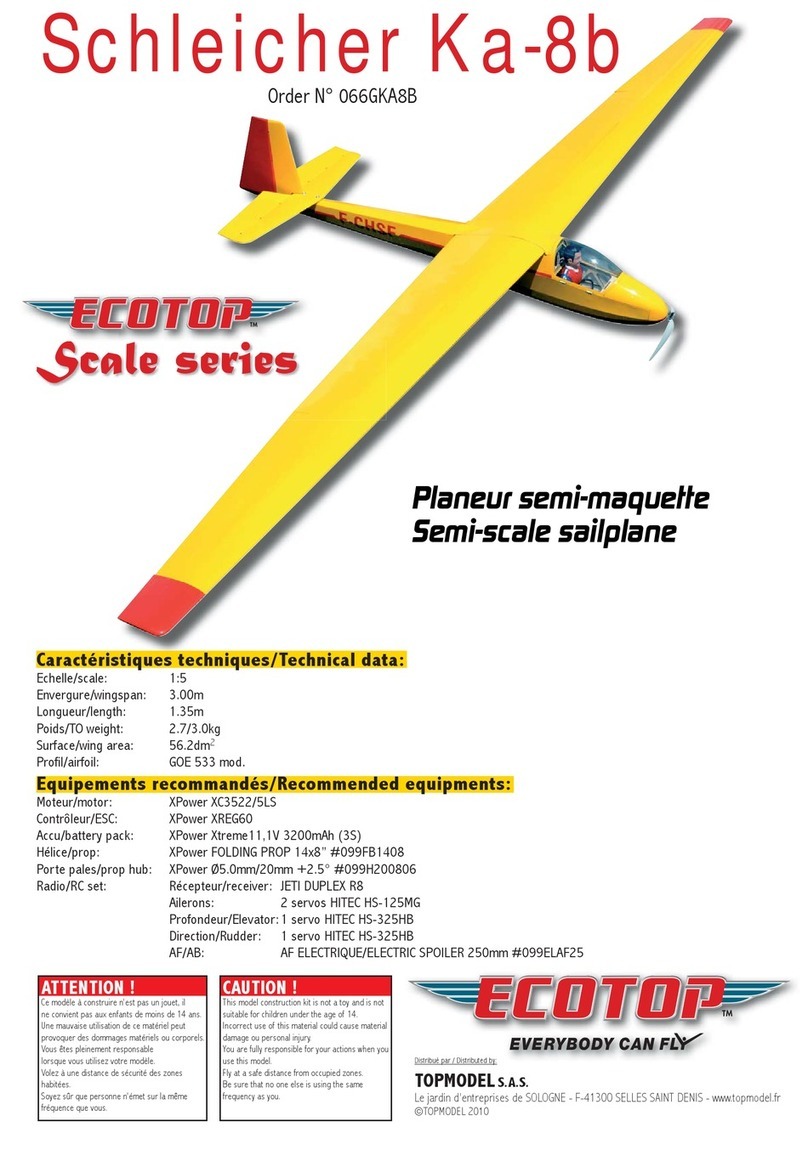
Ecotop Schleicher Ka-8b User manual
Ecotop
Ecotop 066GDHC2 User manual
Ecotop
Ecotop Schleicher Scale Series User manual
Ecotop
Ecotop Schleicher Ka-8b User manual

Ecotop
Ecotop BIDULE 55 User manual
Ecotop
Ecotop PILATUS B4 User manual

Ecotop
Ecotop PILATUS PC-6 TURBO PORTER User manual
Popular Toy manuals by other brands
Playskool
Playskool Batman 16" Power Cycle instructions

goliath
goliath Doggie Doo CORGI instructions

Fisher-Price
Fisher-Price Thomas & Friends TRACK MASTER THOMAS VOLCANO... instructions

Fisher-Price
Fisher-Price DMY02 manual

Mattel
Mattel Barbie T5423-0520 instructions

Radica Games
Radica Games Play TV MONSTER TRUCK 74026 instruction manual
