Lippert Components Manual Step with SolidStance User manual

Manual Step with
SolidStance™
OEM INSTALLATION MANUAL

Rev: 01.10.20 Page 2 CCD-0002727
TABLE OF CONTENTS
Introduction 2
Safety 2
Resources Required 3
Installation 3
Operation 4
Extending Position 4
Stowed Position 5
Introduction
The SolidStance™ Step Stabilizer gives additional support to recreational vehicle steps. The SolidStance Step
Stabilizer has two adjustable support legs with footpads to accommodate the height from the bottom step
to the ground, giving solid and secure support to keep the steps from rocking when in use.
NOTE: Images used in this document are for reference only when assembling, installing and/or operating
this product. Actual appearance of provided and/or purchased parts and assemblies may differ.
For information on the assembly or individual components of this product, please visit:
https://support.lci1.com/steps.
Safety
Read and understand all instructions before installing or operating this product. Adhere to all safety labels.
This manual provides general instructions. Many variables can change the circumstances of the instructions,
i.e., the degree of difficulty, operation and ability of the individual performing the instructions. This
manual cannot begin to plot out instructions for every possibility, but provides the general instructions,
as necessary, for effectively interfacing with the device, product or system. Failure to correctly follow the
provided instructions may result in death, serious personal injury, severe product and/or property damage,
including voiding of the LCI limited warranty.
The "WARNING" symbol above is a sign that a procedure has a safety risk involved and may cause death or
serious personal injury if not performed safely and within the parameters set forth in this manual.
Failure to follow instructions provided in this manual may result in death, serious personal injury
and/or severe product and property damage, including voiding of the component warranty.
The “CAUTION” symbol above is a sign that a safety risk is involved and may cause personal injury
and/or product or property damage if not safely adhered to and within the parameters set forth
in this manual
Rev: 01.10.20 Page 3 CCD-0002727
Always wear eye protection when performing installation procedures. Other safety equipment to
consider would be hearing protection, gloves and possibly a full face shield, depending on
the nature of the task.
Moving parts can pinch, crush or cut. Keep clear and use caution.
Installation
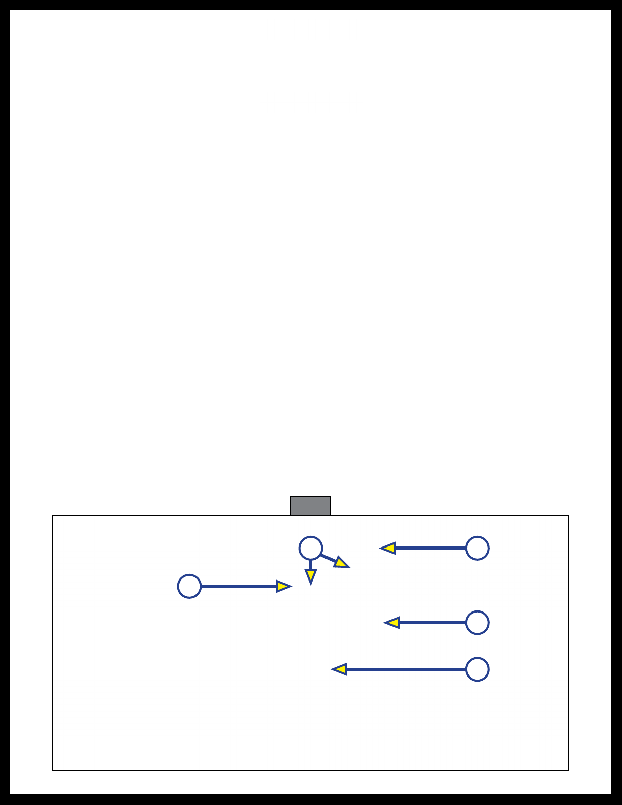
1. Verify the location and squareness of the step outriggers (Fig. 1A).
2. Make sure the step is completely backed up against the I-beam (Fig. 1B).
NOTE: Some OEM designs allow the steps to rest against the I-beam and fasten directly to the web of the
beam. Other designs include step supports and, if supports are present, steps should be completely
backed up against the step supports on the frame (angle or tube).
3. Align holes in step (Fig. 1C) with holes in the outrigger (Fig. 1A). Insert two bolts and flange lock nuts
per side. Tighten only until snug to allow for adjustments.
4. Verify that the step housing (Fig. 1D) is square, level to the outrigger (Fig. 1A) and plumb to the
I-beam (Fig. 1B). Once verified, tighten the bolts to 20 ft-lbs of torque.
NOTE: If step support brackets are located on the step, they should be secured to the chassis I-beam
or step support angles on the chassis by one self-tapping 1" x ¼" screw per each side of the step.
NOTE: The adjustable step bracket is optional and may not be included on all steps.
5. Attach lag bolt or bolts to the floor through the outer end holes in the outrigger (Fig. 1E) as per
manufacturer's recommendations.
Fig. 1
E
B
A
D
Resources Required
• Cordless or electric drill or screw gun
• Appropriate drive bits
• ⁄" socket
• Four ⁄" - 16 x 1" bolts, grade 2
• Four ⁄" - 16 flange nuts, grade 2
• Two self-tapping 1" x ¼" screws, if needed for step
support brackets.
C
Rev: 01.10.20 Page 4 CCD-0002727
Operation
NOTE: The operation of the manual step with SolidStance should NOT be left in the extended position
or used during the manufacture and completion of the trailer. After verifying the manual step
with SolidStance operates in the extended and retracted position, leave the manual step with
SolidStance in the fully retracted position.
Moving parts can pinch, crush or cut. Keep clear and use caution.
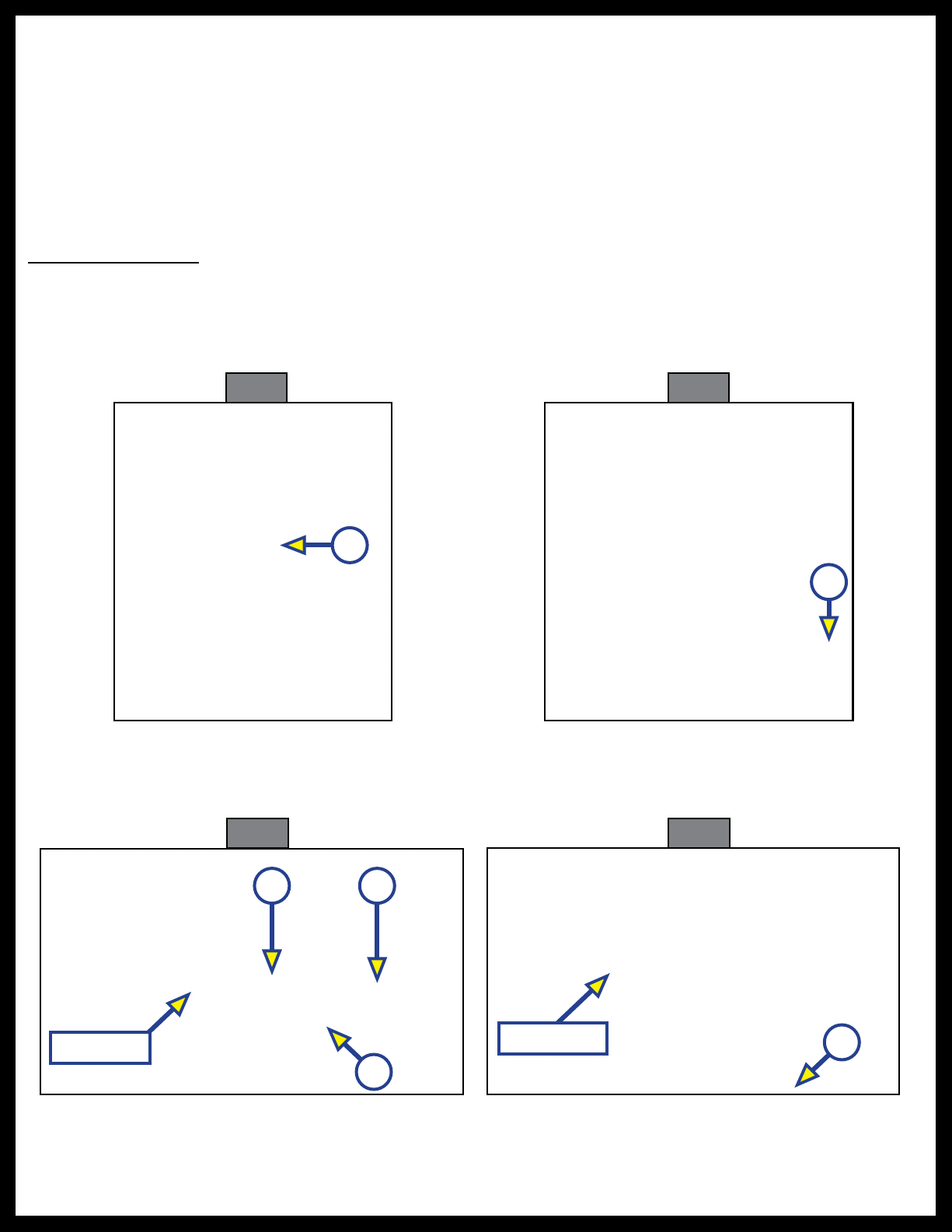
5. Firmly hold of one of the drop legs (Fig. 4A) and pull the quick release fastener pin (Fig. 4B) out of the
drop leg channel (Fig. 4C). Carefully allow the drop leg footpad (Fig. 5A) to touch down to the ground.
6. Do step 5 for the other drop leg.
Fig. 2 Fig. 3
A
Fig. 4 Fig. 5
Rear View
A C
B
Front View A
Extending Position
1. Make sure the trailer is parked on solid level ground.
2. Pull out on the top lip of the vertically stored step (Fig. 2A).
3. Pull up and out on the back of step resting on the second step.
4. Unfold bottom step (Fig. 3A).
A
Rev: 01.10.20 Page 5 CCD-0002727
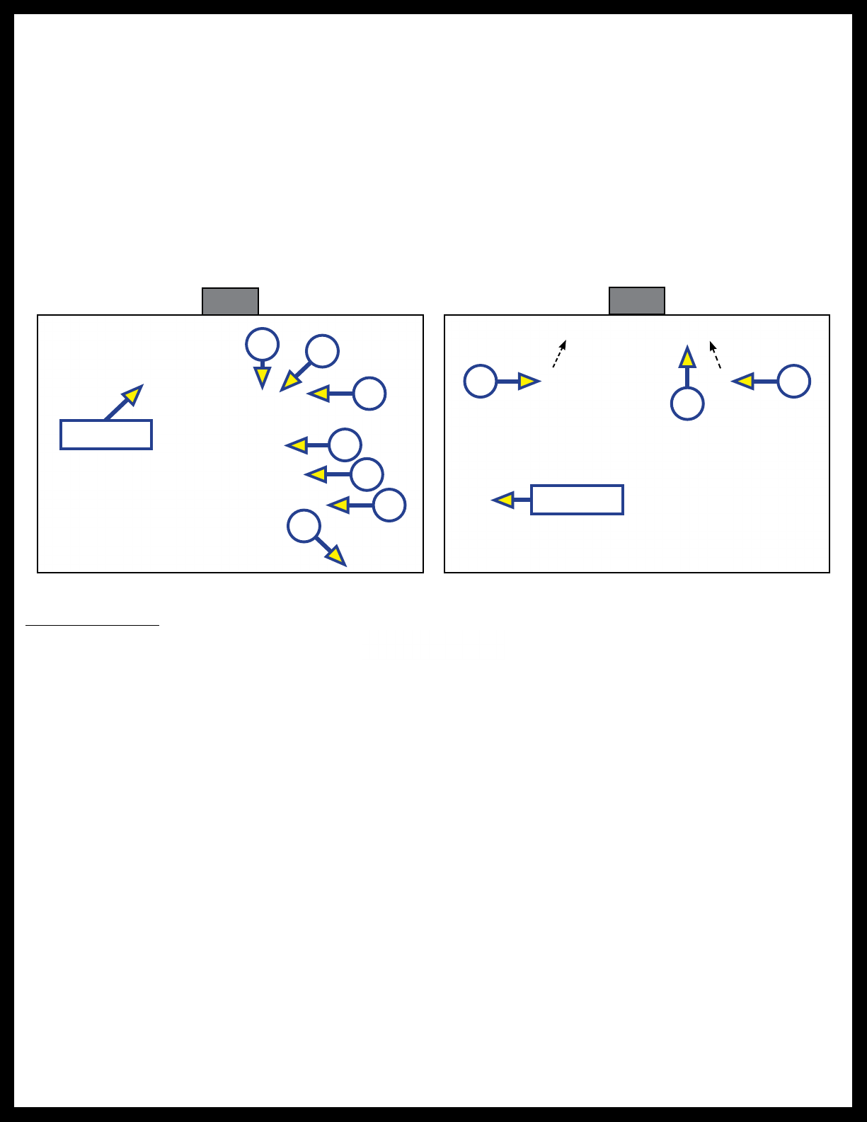
7. If the footpads do not reach the ground, pull the spring loaded pin (Fig. 6B) out on the drop leg to
extend the inner leg (Fig. 6C) down so that the footpad (Fig. 6D) touches down to the ground.
8. Align the closest pin hole in the inner leg (Fig. 6C) to the spring loaded pin (Fig. 6B). Allow the spring
loaded pin to insert into the inner leg to lock it in place.
9. Complete steps 7 and 8 for the other drop leg.
10. There are four drop leg channel angles (Fig. 6E, 6F and 6G) the drop leg can be positioned. Align
the drop leg (Fig. 6A) with the angle required to the closest hole in the drop leg channel to give the
SolidStance a sturdy position with the ground.
11. Insert both fastener pins (Fig. 7A) into the appropriate hole through the back of the drop leg channel
(Fig. 7B) through the drop leg and out the front of the drop leg channel. Make sure the fastener pin
is all the way through to the front of the drop leg channel to secure the drop leg in place.
NOTE: Securing the fastener pins from the back to the front will avoid tripping on the wire lanyard.
Fig. 6 Fig. 7
Rear View
EF
G
A
B
C
D
Rear View
A A
B
Stowed Position
Moving parts can pinch, crush or cut. Keep clear and use caution.
1. Remove both fastener pins (Fig. 7A) from the back of the drop leg channel (Fig. 7B).
2. If the inner legs (Fig. 6C) are extended on the drop legs (Fig. 6A) pull the spring loaded pin (Fig. 6B)
out and slide the inner leg up into the drop leg as far as it will go. Allow the spring loaded pin to insert
into the closest pin hole in the inner leg to lock into place.
3. Complete step 2 for the other drop leg.
4. Move the drop leg (Fig. 4A) up into the base of the drop leg channel (Fig. 4C). Align the holes in the
drop leg with the holes in the drop leg channel.
5. Insert the fastener pin (Fig. 7A) into the drop leg channel (Fig. 7B), through the drop leg and out the
front of the drop leg channel. Make sure the fastener pin is all the way through to the front of the drop
leg channel to secure the drop leg in place.
NOTE: Securing the fastener pins from the back to the front will avoid tripping on the wire lanyard.
6. Pull up on bottom step (Fig. 3A) and fold over the second step.
7. Pull up on bottom of steps and fold inward under top step (Fig. 2A).

The contents of this manual are proprietary and copyright protected by Lippert Components, Inc. (LCI).
LCI prohibits the copying or dissemination of portions of this manual unless prior written consent from an
authorized LCI representative has been provided. Any unauthorized use shall void any applicable warranty.
The information contained in this manual is subject to change without notice and at the sole discretion of LCI.
Revised editions are available for free download from lci1.com.
Please recycle all obsolete materials.
For all concerns or questions, please contact
Lippert Components, Inc.
Table of contents


