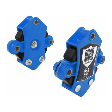
Lippert Components Road Armor Triple Axle User manual

Rev: 06.12.2018
™
®

Rev: 06.12.18 Page 2 CCD-0001410
System Information
The Lippert Component, Inc. Road Armor™features a new stamped steel design, integrating both time-
proven natural rubber inserts and oil impregnated bushings for smoother travel. The Road Armor was
designed as a “drop-in” replacement for a standard equalizer setup, which means there is no drilling or
welding needed for installation.
Safety Information
The load rating is 3,500 pounds to 8,000 pounds for the Road Armor Triple Axle Equalizers.
Incorrect raising or lowering of the trailer could result in death, serious injury, and or damage to the trailer.
Make sure the trailer is properly supported before performing any trailer work. Follow the trailer manufacturer's
recommendations for lifting and supporting the trailer. Use proper personal protective equipment.
• 1 to 2 Persons, Depending on
Task
• Pneumatic Air or Impact Gun
• Torque Wrench
• Cordless or Electric Drill or
Screw Gun
• Appropriate Drive Bits
• Hammer
• Vice to Hold Correct Track Cam
Plate to Install Bolts (Optional)
• ⁄" Deep Well Socket
• ¾" Deep Well Socket
• ⁄" Deep Well Socket
• Steel Tube to Install Bolts with
Grease Fittings
• Appropriately-sized and rated
bolts and fasteners
TABLE OF CONTENTS
System Information 2
Triple Axle Equalizer Options 2
Safety Information 2
Resources Required 2
Installation 3
Rear Equalizer (Between 2nd and 3rd Axles) 3
Front Equalizer (Between 1st and 2nd Axles) 4
Final Component Installation 5
Optional Wheel Installation 5
Triple Axle Equalizer Options
Two Road Armor Triple Axle Equalizers are available, including long arm and short arm versions, with
utilization dependent on axle spacing. Trailers that measure 35” from the center of the first wheel to the
center of the second wheel will use the 9.54” long arm version. Trailers that measure 33" between the center
of the first wheel to the center of the second wheel will use the 8.67” short arm version.
Resources Required

Rev: 06.12.18 Page 3 CCD-0001410
Installation
Rear Equalizer (Between 2nd and 3rd Axles)
NOTE: Support framework in accordance with manufacturer's recommendations.
NOTE: When utilizing the Correct Track system, the shorter shoulder bolt will be used to install the rear
equalizer to the hangers. The cam plates are not installed on the rear hanger.
Reference Fig. 1 for the following procedural steps:
1. Install the Road Armor into the hanger. Make sure the Road Armor label is facing outward.
2. Install the equalizer bolt through the first bracket of the hanger, then through the topmost bronze
bushing of the Road Armor equalizer and, finally, through the second bracket of the hanger.
3. Use a hammer or a piece of steel tube (for bolts with grease fittings) and drive the equalizer bolt into
the hanger. This will seat the serrations of the bolt against the hanger surface and provide resistance to
rotation when tightening.
NOTE: The equalizer bolt must be installed from the outside in toward the center of the trailer chassis. This
ensures the bolt threads do not interfere with any other assemblies. This applies to bolts with or
without grease fittings.
4. Install the nut onto the equalizer bolt until the nut seats against the shoulder bolt. Torque nut to 30-50
ft-lbs.
NOTE: When installing the equalizer bolt nuts, use a wrench to hold the bolt heads.
5. Repeat Steps 1 through 4 for opposite side of the trailer.
Fig. 1
Fig. 2
Shackle Bolts
Equalizer
Bolt
Frame Rail
Hanger
Road Armor Equalizer
Shackle Link
Pivot Arm
Rotation
Stop
Leaf
Spring
Fig. 1

Rev: 06.12.18 Page 4 CCD-0001410
Front Equalizer (Between 1st and 2nd Axles)
NOTE: Support framework in accordance with manufacturer's recommendations.
NOTE: There is a left hand (LH) and a right hand (RH) Triple Axle Road Armor Equalizer. The fixed arm must
always face toward the rear of the trailer.
NOTE: If the Correct Track system is installed, this procedure will take the longer shoulder bolt. Cam plates
are installed on the front triple equalizer hanger.
Reference Fig. 2, which illustrates a roadside installation, for the following procedural steps:
1. Install the triple axle equalizer on the roadside hanger with the fixed arm facing the rear of the trailer
and with the Road Armor logo facing outward.
2. Install the equalizer bolt through the first bracket of the hanger, then through the topmost bushing of
the Road Armor equalizer and, finally, through the second bracket of the hanger.
3. Use a hammer or a piece of steel tube (for bolts with grease fittings) and drive the equalizer bolt into
the hanger. This will seat the serrations of the bolt against the hanger surface and provide resistance to
rotation when tightening.
NOTE: The equalizer bolt must be installed from the outside in toward the center of the trailer chassis. This
ensures the bolt threads do not interfere with any other assemblies. This applies to bolts with or
without grease fittings.
4. Install the nut onto the equalizer bolt until the nut seats against the shoulder bolt. Torque nut to 30-50 ft-lbs.
NOTE: When installing the equalizer bolt nuts, use a wrench to hold the bolt heads.
5. Repeat Steps 1 through 4 for the opposite side of the trailer, making sure the fixed arm faces toward
the rear.
Leaf Spring
Road Armor
Fixed Arm
Equalizer
Bolt
Hanger
Frame Rail
Shackle Bolts
Rear of Trailer
Front of Trailer
Fig. 2
Pivot Arm
Shackle Link
Leaf Spring

Rev: 06.12.18 Page 5 CCD-0001410
Final Component Installation
Place the axles into their normal operating position.
Reference Fig. 3, which illustrates a roadside installation, and Fig. 4, which illustrates a curbside installation,
for the following procedural steps:
NOTE: When installing the nuts, use a wrench to hold the bolt heads.
1. For Axle 1 and Axle 3, attach the leaf springs to the hangers with shoulder bolts and nuts.
2. For Axle 2, attach the leaf spring to the fixed arm of Triple Axle Equalizer with shackle bolt and nut,
included within kit.
NOTE: A longer shoulder bolt must be used to attach the leaf spring to the Road Armor fixed arm.
3. For Axle 1, Axle 2 and Axle 3, attach all shackle links to the Road Armor pivot arm bushings and the leaf
springs with shackle bolts and nuts.
4. Tighten all nuts until they bottom out on the shoulder bolt at 30-50 ft-lbs.
5. Repeat Steps 1 through 4 for the opposite side of the trailer.
6. The LCI Triple Axle Road Armor installation is complete.
Rear of Trailer
Front of Trailer
Axles and Wheels
Removed For Clarity
Axle #2
Triple Axle
Equalizer
Tandem Axle
Equalizer
Axle #1 Axle #3
Front of Trailer
Rear of Trailer
Triple Axle
Equalizer
Tandem Axle
Equalizer
Axle #1
Axle #2
Axle #3
Axles and Wheels
Removed For Clarity
Roadside View of Trailer
Curbside View of Trailer
Fig. 3
Fig. 4
Optional Wheel Installation
1. Install wheels and apply lug nuts in a star fashion and torque as per manufacturer’s specifications.
2. Lower the trailer evenly to the ground. Use care to avoid jarring movement. The trailer MUST not be
dropped to the ground. Make sure the shackle links are upright and located approximately in the 10
o'clock and 2 o'clock position (Fig. 3 and Fig. 4).

The contents of this manual are proprietary and copyright protected by Lippert Components, Inc. (“LCI”).
LCI prohibits the copying or dissemination of portions of this manual unless prior written consent from an
authorized LCI representative has been provided. Any unauthorized use shall void any applicable warranty.
The information contained in this manual is subject to change without notice and at the sole discretion of LCI.
Revised editions are available for free download from lci1.com / support.
Please recycle all obsolete materials.
For all concerns or questions, please contact
Lippert Components, Inc.
Rev: 06.12.2018
Table of contents
Other Lippert Components Stereo Equalizer manuals
