Lippert 104X-E4690 User manual

TME-104X-E4690-1V0.doc
Revision 1.0 / April 11
©LiPPERT Embedded Computers GmbH
Hans-Thoma-Str. 11
D-68163 Mannheim
www.lippertembedded.com
104X-E4690
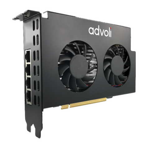
PCI/104-Express Graphics Card
Technical Manual

TME-104X-E4690-1V0.doc Rev 1.0
Technical Manual 104X-E4690
LiPPERT Document: TME-104X-E4690-1V0.doc, Revision 1.0
Copyright © 2010-2011 LiPPERT Embedded Computers GmbH, all rights reserved
Trademarks
Windows is a trademark of Microsoft Corporation. AMD, the AMD arrow logo, ATI, the ATI logo, Radeon, and
combinations thereof are trademarks of Advanced Micro Devices, Inc. PCI/104-Express is a registered trademark
of PC/104 Consortium. All other trademarks appearing in this document are the property of their respective
owners.
Disclaimer
Contents and specifications within this technical manual are subject of change without notice.
LiPPERT Embedded Computers GmbH provides no warranty with regard to this technical manual or any other
information contained herein and hereby expressly disclaims any implied warranties of merchantability or fitness
for any particular purpose with regard to any of the foregoing. LiPPERT Embedded Computers GmbH assumes no
liability for any damages incurred directly or indirectly from any technical or typographical errors or omissions
contained herein or for discrepancies between the product and the technical manual. In no event shall LiPPERT
Embedded Computers GmbH be liable for any incidental, consequential, special, or exemplary damages, whether
based on tort, contract or otherwise, arising out of or in connection with this user’s guide or any other information
contained herein or the use thereof.

TME-104X-E4690-1V0.doc Rev 1.0 i
Table of Contents
1Overview 1
1.1 Introduction ........................................................................................................................1
Features ....................................................................................................................................1
Block Diagram...........................................................................................................................2
1.2 Ordering Information...........................................................................................................3
104X-E4690 Models..................................................................................................................3
Accessories...............................................................................................................................3
1.3 Specifications .....................................................................................................................4
Electrical Specifications............................................................................................................4
Environmental Specifications....................................................................................................4
MTBF.........................................................................................................................................4
1.4 Mechanical .........................................................................................................................5
TOP...........................................................................................................................................6
2Getting Started 7
2.1 Connector Locations ..........................................................................................................7
Top ............................................................................................................................................7
2.2 Hardware setup ..................................................................................................................8
2.3 Cooling solutions ................................................................................................................9
Heat spreader ...........................................................................................................................9
Heat pipe adapter .................................................................................................................. 10
Heat sink active...................................................................................................................... 10
3Module Description 11
3.1 Interfaces..........................................................................................................................11
VGA (X6, X10)......................................................................................................................... 11
DisplayPort (DP) Connector (X1 (X12), X2 ( X13)) .................................................................. 12
Integrated HD Audio Controller (Azalia) and Codec .............................................................. 12
LVDS (X3) ............................................................................................................................... 13
LVDS Color Mapping ............................................................................................................. 14
Backlight (X5) ......................................................................................................................... 14
Display Voltage Jumpers (X4) ................................................................................................ 15
3.2 PC/104-Plus Bus Interface (X11).......................................................................................16
3.3 PCI/104-Express Bus Interface (X7) ..................................................................................17
TME-104X-E4690-1V0.doc Rev 1.0 ii
3.4 Fan Connector (X9) ...........................................................................................................18
4Using the Module 19
4.1 Drivers ..............................................................................................................................19
Scalable Power Consumption ............................................................................................... 19
Appendix A, Contact Information A
Appendix B, Additional Information B
Appendix C, Getting Help C
Appendix D, Revision History D

TME-104X-E4690-1V0.doc Rev 1.0 iii
Acronyms
ACPI Advanced Configuration and Power Management Interface
AMD Advanced Micro Peripherals
BIOS Basic Input Output System
BPP Bits Per Pixel
CPU Central Processing Unit
CRT Cathode Ray Tube
DAC Digital-to-Analog-Converter
DC Direct Current
DDR Double Date Rate
DMA Direct Memory Access
EMC Electromagnetic Compatibility
HDA High Density Audio
I²C Inter-Integrated Circuit
LCD Liquid Crystal Display
LED Light Emitting Diode
LVDS Low Voltage Differential Signaling
PCIe Peripheral Component Interconnect Express
PLL Phase-Locked Loop
PWM Pulse Width Modulation
PWR Power
ROM Read Only Memory
SBC Single Board Computer
SMB System Management Bus
SMC System Management Controller
SPI Serial Peripheral Interface
VGA Video Graphics Array

TME-104X-E4690-1V0.doc Rev 1.0 1(19)
1Overview
1.1 Introduction
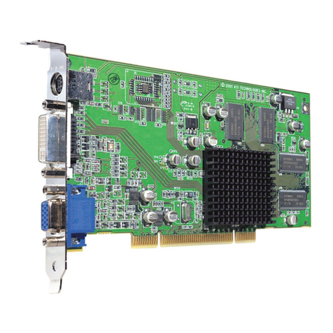
The 104X-E4690 is a graphics card with an ATI Radeon™ E4690 graphics processor for embedded applications
with an excellent performance power ratio. The board adds unprecedented graphics performance to an
embedded PC on a small 3.78" by 3.55" printed circuit board.
Based on 55nm technology, the E4690 delivers more than double the performance per watt* than previous
generation processors. Built with ATI’s PowerPlay™ technology the E4690 has dynamic power management
delivering high performance when needed, while intuitively conserving energy at idle or when demand is low. The
E4690 graphics processor also allows for exceptional scalability of performance between 8W and 25W.For analog
monitors there is a VGA-interface and digital ones can be connected to LVDS or Display Port. Backlighting is
provided for LCD modules, too.
For larger projects, the Display Port and VGA connectors can be left unstuffed while display cables can be
soldered directly onboard.
System expansion can easily be realized over PCI/104-Express and PC/104-Plus bus connectors.
The 104X-E4690 is powered by the PCI/104-Express and PC/104-Plus bus connectors and needs no additional
power supply.
The 104X-E4690 runs at Linux, Windows XP, Windows XP Embedded, Windows Vista and Windows 7.
Features
GPU
•ATI Radeon™ E4690
•CPU Interface PCIe 2.0 (x1, x2, x4, x8, x16)
•320 Shader Processing Units
•AVIVO Display Engine
•Full 30-bit Display Pipeline
•Stream Computing
Main Memory
•512MByte GDDR3 700 MHz RAM (128Bit)
Graphics Acceleration
•DirectX 10.1
•Shader Model 4.0
•OpenGL 3.x
•OpenCL (2H09)
•Motion Video Decode for H.264, VC-1,
MPEG2
Extension slots
•1 x 32-bit PC/104-Plus 22 mm height on top
•1 x PCI/104-Express 22m height on top
Interfaces
•VGA
•2 x DisplayPort (v1.1a)
•18Bit or 24Bit Dual Channel LVDS
Other Features
•Integrated HD Audio Controller (Azalia)
•Temperature Controlled Fan
Other configurations are possible. Please contact your local LiPPERT representative to discuss requirements.

TME-104X-E4690-1V0.doc Rev 1.0 2(19)
Block Diagram
ATI
RadeonTM E4690
512MB on chip
memory
DisplayPortA
DisplayLinkA
DisplayLinkB
DAC1Link
DisplayLinkE/F
DisplayPortB
VGA
24BitLVDS(DualChannel)
PCIex16PCI/104-Express

TME-104X-E4690-1V0.doc Rev 1.0 3(19)
1.2 Ordering Information
104X-E4690 Models
Order number
Description
712-0007-10 104X-E4690
Operating temp. range: 0°C…+60°C
812-0007-10 104X-E4690
Operating temp. range: -20°C…+60°C
Accessories
There are some options available for the 104X-E4690. Please check their availability before ordering.
Order number
Description
765-0033-10
765-0034-10
765-0026-10
Heat spreader 104X-E4690 (already included on delivery)
Heat Pipe Adapter 104X-E4690
Heat sink active 104X-E4690

TME-104X-E4690-1V0.doc Rev 1.0 4(19)
1.3 Specifications
Electrical Specifications
Supply voltage +5 V DC
Rise time < 10 ms
Supply voltage tolerance ± 5%
Inrush current t.b.d.
Supply current +5 V DC / max. 5A
+3.3V DC / max. 2A
Environmental Specifications
Operating:
Temperature range 0 … 60 °C (standard version)
-20 … 60 °C (industrial version)
Temperature change 10K / 30 minutes maximum
Humidity (relative) 10 … 90 % (non-condensing)
Pressure 450 … 1100 hPa
Non-Operating/Storage/Transport:
Temperature range -55 … 85 °C
Temperature change
10K / 30 minutes maximum
Humidity (relative) 5 … 95 % (non-condensing)
Pressure
450 … 1100 hPa
MTBF
MTBF at 25°C 450.937 hours

TME-104X-E4690-1V0.doc Rev 1.0 5(19)
1.4 Mechanical
Dimensions (L x W) 90.2 mm x 95.9 mm
Height max. 11mm on topside above PCB (without bus connectors)
max. 5 mm on bottom side above PCB (without bus connectors)
Weight approx 90 gr. without cooling solution
approx 250 gr. with active heat sink
Mounting 4 mounting holes as defined in the PCI/104-Express specification
4 mounting holes for cooling device
Note:
It is strongly recommend using plastic spacers instead of metal spacers to mount
the board. With metal spacers, there is a possible danger to create a short circuit
with the components located around the mounting holes. This can damage the
board!

TME-104X-E4690-1V0.doc Rev 1.0 6(19)
TOP
Pin1 Pin2

TME-104X-E4690-1V0.doc Rev 1.0 7(19)
2Getting Started
2.1 Connector Locations
Top

TME-104X-E4690-1V0.doc Rev 1.0 8(19)
2.2 Hardware setup
Caution
Be sure to observe the EMC security measures. Make sure you are always at the
same potential as the module.
Caution
Never connect or disconnect peripherals like PCI while the board's power supply
is connected and switched on!
Plug the 104X-E4690 module on top or under a PCI/104-Express or EPIC-Express single board computer (SBC).
Connect the 104X-E4690 to a VGA or Display Port monitor. Connect USB keyboard and mouse to the SBC. Use
the soldered SSD or connect a hard drive with a SATA cable (not part of the cable set) to start an operation
system. Make sure that the pins match their counterparts correctly and are not twisted! If you plan to use
additional other peripherals, now is the time to connect them, too.
Connect an appropriate power supply to the power connector of the SBC and switch the power on.
Note
Be sure that your power supply is able to handle the overall inrush current!
Depending on the used SBC it might be necessary to change the primary display output in the SBC bios setup to
´PCI-Express´ or ´external VGA´ to get a screen output on the 104X-E4690. Please refer to the technical manual of
the used SBC.
The 104X-E4690 needs additional cooling measures. Depending on the required graphics performance the fan will
be controlled in speed to achieve the best cooling performance.
Jumper X5

TME-104X-E4690-1V0.doc Rev 1.0 9(19)
2.3 Cooling solutions
The following solutions are available for the 104X-E4690 as cooling device. Please ask our support department for
detailed 3D drawings.
Heat spreader
part number 765-0033-10
The heat spreader is included as default on the board. Additional cooling is necessary for the operation of the
board by mounting an adequate cooling device on the heat spreader. With such an additional cooling device the
heat spreader is suitable for a temperature range up to 60°C ambient temperature.

TME-104X-E4690-1V0.doc Rev 1.0 10(19)
Heat pipe adapter
part number 765-0034-10
The heat pipe adapter is optionally available to use an 8 mm heat pipe and an condenser with adequate heat sink
on the other end of the heat pipe for cooling. With such an additional cooling device the heat pipe adapter is
suitable for a temperature range up to 60°C ambient temperature. Please note that the 8 mm heat pipe is not
included.
Heat sink active
part number 765-0026-10
The active heat sink is optionally available and is suitable for a temperature range up to 60°C ambient
temperature. Please note that the heat sink height does not allow to stack an additional PC/104 Express board on
top of the 104X-E4690. Depending on the required graphics performance the fan will be controlled in speed to
achieve the best cooling performance.

TME-104X-E4690-1V0.doc Rev 1.0 11(19)
3Module Description
3.1 Interfaces
VGA (X6, X10)
The analog display port provides a RGB signal output along with a HSYNC and VSYNC signal.
There is an associated DDC signal pair that is implemented on the analog port. The intended target device is for a
CRT based monitor with a VGA connector.
Display devices such as LCD panels with analog inputs may work satisfactory but no functionality has been added
to the signals to enhance that capability.
The display function contains a RAM-based Digital-to-Analog Converter (RAMDAC) that transforms the digital data
from the graphics and video subsystems to analog data for the CRT monitor. Maximum pixel frequency is
400MHz. Three 10-bit DAC provide the R, G, and B signals to the monitor.
Connector type
DSUB15 HDF
Pin
Signal
Pin
Signal
1 Red 2 Green
3 Blue 4 Reserved
5 GND 6 GND
7 GND 8 GND
9 +5V 10 GND
11 Reserved 12 DDC_DAT
13 HSYNC 14 VSYNC
15 DDC_CLK
Note
The +5Vsignal at pin 9 is protected by a 3A fuse. The fuse gets damaged if this pin is
shorted to ground!
There is an additional through-hole pattern that allows soldering a VGA cable directly on the board.
Pin
Signal
Pin
Signal
1 Red 2 GND
3 Green 4 Reserved
5 Blue 6 DDC_CLK
7 HSYNC 8 DDC_DAT
9 VSYNC 10 GND

TME-104X-E4690-1V0.doc Rev 1.0 12(19)
DisplayPort (DP) Connector (X1 (X12), X2 ( X13))
Two DisplayPort monitors can be used at the same time, each working with a maximum resolution of 2560 x 1600
pixels at 60Hz refresh rate.
Connector type: Molex 47272-0021
Pin
Signal
Pin
Signal
1 TD0+ 2 GND
3 TD0- 4 TD1+
5 GND 6 TD1-
7
TD2+
8
GND
9 TD2- 10 TD3+
11 GND 12 TD3-
13
GND (CONFIG1)
14
GND (CONFIG2)
15 AUX+ 16 GND
17 AUX- 18 HPDET
19
GND (RETURN)
20
+3.3V
Integrated HD Audio Controller (Azalia) and Codec
•Integrated HD Audio codec supports linear PCM and Dolby® Digital (7.1) audio formats for HDMI and
DisplayPort outputs. (Note: Player applications may limit the audio output capabilities.)
•Separate logical chip function.
•Can encrypt data onto one associated HDMI or DisplayPort output.
•Compatible Microsoft UAA driver support for basic audio.
•For advanced functionality, a 3rd party driver is required.
•Internally connected to the integrated HDMI or DisplayPort interface, hence no external cable required.
•Support for basic audio (32, 44.1 or 48-kHz stereo) and Dolby® Digital or DTS at the same sample
rates.
•LPCM PCM multi-channel support with up to 24-bps and 192-kHz sampling rate.
•Support for up to 8 channels.
•HDCP content protection support for software audio stack.
•True audio plug-and-play capability for enhanced audio modes.

TME-104X-E4690-1V0.doc Rev 1.0 13(19)
LVDS (X3)
•Single-link or dual-link LVDS transmitter takes output from either one of the internal display controllers.
•LVDS can operate in either single- or dual-channel mode supporting displays from XGA (or below) up to
QXGA.
•LVDS can drive either 18-bpp or 24-bpp displays with several dithering options from the internal 30-bpp
display controller.
•Ratio metric expansion and compression supported on reduced blank panels.
•3 pairs (+1 clock) and 4 pairs (+1 clock) modes for both single- and dual-channel LVDS.
•FPDI-2 compliant; compatible with receivers from National Semiconductor, Texas Instruments, and
THine.
Connector type DF14 30-pin header
1 1.0A is the maximum current for each pin
Pin Signal
1 VDD (3.3 V, opt.5 V) 1
2
VDD (3.3 V, opt.5 V) 1
3 GND
4 GND
5 TXA3 -
6 TXA3 +
7 TXACLK -
8 TXACLK +
9 GND
10 TXA2 -
11 TXA2 +
12 TXA1 -
13 TXA1 +
14 TXA0 -
15 TXA0 +
16 GND
17 TXB3 -
18 TXB3 +
19 TXBCLK -
20 TXBCLK +
21 GND
22 TXB2 -
23 TXB2 +
24 TXB1 -
25 TXB1 +
26 TXB0 -
27 TXB0 +
28 GND
29 LVDS DDC-CLK
30 LVDS DDC-DATA
X3

TME-104X-E4690-1V0.doc Rev 1.0 14(19)
LVDS Color Mapping
1
2
3
4
5
6
7
CLKA
1 1 0 0 0 1 1
A0
G2 R7 R6 R5 R4 R3 R2
A1
B3 B2 G7 G6 G5 G4 G3
A2
DE VS HS B7 B6 B5 B4
A3
0/B1 B1 B0 G1 G0 R1 R0
CLKB
1 1 0 0 0 1 1
B0
G2 R7 R6 R5 R4 R3 R2
B1
B3 B2 G7 G6 G5 G4 G3
B2
DE VS HS B7 B6 B5 B4
B3
0/B1 B1 B0 G1 G0 R1 R0
In 18 Bit mode A3 and B3 will be unused.
In Dual Link Mode channel A contains even bits, channel B contains odd bits.
Backlight (X5)
In order to meet the panel power timing specification requirements the LCD backlight inverter power supply is
controlled by an integrated PWM interface.
Connector type DF13 8-pin header
Pin
Signal
1 +12V 2
2
+12V 2
3 +5V 2
4 +5V 2
5
CTRL
6 EN 3
7
GND
8 GND
20.5A is the maximum current for each pin
3That voltage can be selected via Jumper for backlight, shown on next page
X5

TME-104X-E4690-1V0.doc Rev 1.0 15(19)
Display Voltage Jumpers (X4)
Jumper LVDS and Backlight
Connector type IDC6 jumper 2.00 mm.
Use a 2 mm jumper between 1-3 or 3-5 to select the display voltage.
Use a 2 mm jumper between 2-4 or 4-6 to select the backlight voltage.
Pin
Signal
Pin
Signal
1 +3.3 Volt 2 +12 Volt
3 Display voltage 4 Backlight voltage
5 + 5 Volt 6 +5 Volt
LVDS
Jumper 1-3 3-5
Power supply +3.3 Volt +5 Volt
Backlight
Jumper 2-4 4-6
Power supply +12 Volt +5 Volt
Note
An arrow marks pin 1
default jumper setting
X4
Table of contents