liquidarc Maxmig 210i User manual

A Division of The Lincoln Electric Company (Aust) Pty Ltd A.B.N. 36 000 040 308
35 Bryant Street, Padstow, Sydney 2211, Australia
SAFETY DEPENDS ON YOU
LiquidArc machines are designed and built with safety in mind. However, your overall safety can be
increased by proper installation . . . and thoughtful operation on your part. Read and observe the general
safety precautions on page 2 and follow specific installation and operating instructions included in this
manual.
Most importantly, think before you act and be careful.
IMA 578BLA
July 2003
Maxmig 210i Part No 05-3210
Maxmig 210R Part No. 05-4210
Operating Manual
CODE MACHINE
70008 05-3210
70009 05-4210

Page 2 Maxmig 210 IMA 578BLA
PROTECT YOURSELF AND OTHERS FROM POSSIBLE SERIOUS INJURY OR DEATH. READ AND UNDERSTAND BOTH
THE SPECIFIC INFORMATION GIVEN IN THE OPERATING MANUAL FOR THE WELDER AND/OR OTHER EQUIPMENT
TO BE USED AS WELL AS THE FOLLOWING GENERAL INFORMATION.
ARC WELDING SAFETY PRECAUTIONS
1. a. The electrode and work (or ground) circuits are
electrically “hot” when the welder is on. Do not touch
these “hot” parts with your bare skin or wet clothing.
Wear dry, hole-free gloves to insulate hands.
b. In semi-automatic and automatic wire welding, the
electrode, electrode reel, welding head and nozzle or
semi-automatic welding gun are also electrically “hot”.
c. Insulate yourself from work and ground using dry
insulation. When welding in damp locations, on metal
framework such as floors, gratings or scaffolds, and
when in positions such as sitting or Lying, make certain
the insulation is large enough to cover your full area of
physical contact with work and ground.
d. Always be sure the work cable makes a good electrical
connection with the metal being welded. The
connection should be as close as possible to the area
being welded.
e. Ground the work or metal to be welded to a good
electrical (earth) ground.
f. Maintain the electrode holder, work clamp, welding
cable and welding machine in good, safe operating
condition. Replace damaged insulation.
g. Never dip the electrode holder in water for cooling.
h. Never simultaneously touch electrically “hot” parts of
electrode holders connected to two welders because
voltage between the two can be the total of the open
circuit voltage of both welders.
i. When working above floor level, protect yourself from
a fall should you get a shock.
j. Also see items 4c and 6.
2. a. Welding may produce fumes and gases hazardous to
health. Avoid breathing these fumes and gases. When
welding, keep your head out of the fume. Use enough
ventilation and/or exhaust at the arc to keep fumes and
gases away from the breathing zone. When welding
on galvanised, lead or cadmium plated steel and other
metals which produce toxic fumes, even greater care
must be taken.
b. Do not weld in locations near chlorinated hydrocarbon
vapours coming from degreasing, cleaning or spraying
operations. The heat and rays of the arc can react with
solvent vapours to form phosgene, a highly toxic gas,
and other irritating products.
c. Shielding gases used for arc welding can displace air
and cause injury or death. Always use enough
ventilation, especially in confined areas, to ensure
breathing air is safe.
d. Read and understand the manufacturer’ s instructions
for this equipment and the consumables to be used,
including the material safety data sheet (MSDS) and
follow your employer’s safety practices.
e. Also see Item 7b.
3. a. Use a shield with the proper filter and cover plates to
protect your eyes from sparks and the rays of the arc
when welding or observing open arc welding.
Headshield and filter lens should conform to AS
1674.2-1990 standards.
b. Use suitable clothing made from durable flame
resistant material to protect your skin and that of your
helpers from the arc rays.
c. Protect other nearby personnel with suitable non
flammable screening and/or warn them not to watch
the arc or expose themselves to the arc rays or to hot
spatter or metal.
4. a. Remove fire hazards from the welding area. If this is
not possible, cover them to prevent the welding sparks
from starting a fire. Remember that welding sparks
and hot materials from welding can easily go through
small cracks and openings to adjacent areas. Have a
fire extinguisher readily available.
b. Where compressed gases are to be used at the job
site, special precautions should be used to prevent
hazardous situations. Refer to AS1674 Parts 1 & 2
“Safety in Welding and Allied Processes”, WTIA
Technical Note 7 “Health and Safety in Welding” and
the operating information for the equipment being
used.
c. When not welding, make certain no part of the
electrode circuit is touching the work or ground.
Accidental contact can cause overheating and create
a fire hazard.
d. Do not heat, cut or weld tanks, drums or containers
until the proper steps have been taken to insure that
such procedures will not cause flammable or toxic
vapours from substances inside. These can cause an
explosion even though the vessel has been “cleaned”.
For information purchase AS 1674-1990.
e. Vent hollow castings or containers before heating,
cutting or welding. They may explode.
f. Sparks and spatter are thrown from the welding arc.
Wear oil free protective garments such as leather
gloves, heavy shirt, cuffless trousers, high shoes and
a cap over your hair. Wear ear plugs when welding out
of position or in confined places. Always wear safety
glasses with side shields when in a welding area.
g. Connect the work cable to the work as close to the
welding area as possible. Work cables connected to
the building framework or other locations away from
the welding area increase the possibility of the welding
current passing through lifting chains, crane cables or
other alternate circuits. This can create fire hazards or
overheat lifting chains or cables until they fail.
h. Also see Item 7c.
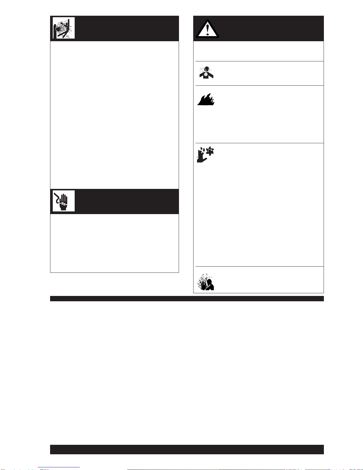
ELECTRIC SHOCK can kill
FUMES AND GASES
can be dangerous
ARC RAYS can burn
WELDING SPARKS can
cause fire or explosion
IMA 578BLA Maxmig 210 Page 3
5. a. Use only compressed gas cylinders containing the
correct shielding gas for the process used and
properly operating regulators, designed for the gas
and pressure used. All hoses, fittings, etc. should be
suitable for the application and maintained in good
condition.
b. Always keep cylinders in an upright position and
securely chained to an undercarriage or fixed support.
c. Cylinders should be located :
• Away from areas where they may be struck or
subjected to physical damage.
• A safe distance from arc welding or cutting
operations and any other source of heat, sparks or
flame.
d. Never allow the electrode, electrode holder, or any
other electrically “hot” parts to touch a cylinder.
e. Keep your head and face away from the cylinder valve
outlet when opening the cylinder valve.
f. Valve protection caps should always be in place and
hand-tight except when the cylinder is in use or
connected for use.
g. Read and follow the instructions on compressed gas
cylinders and associated equipment, and AS 2030
Parts 1 & 2.
6. a. Turn off input power using the disconnect switch at the
fuse box before working on the equipment.
b. Install equipment in accordance with the SAA Wiring
Rules, all local codes and the manufacturer’s recom-
mendations.
c. Ground the equipment in accordance with the SAA
Wiring Rules and the manufacturer’s recommenda-
tions.
7. a. Turn the engine off before troubleshooting
and maintenance work unless the
maintenance work requires it to be running.
b. Operate engines in open, well ventilated
areas or vent the engine exhaust fumes
outdoors.
c. Do not add fuel near an open flame,
welding arc or when the engine is running.
Stop the engine and allow it to cool before
refuelling to prevent spilled fuel from
vaporizing on contact with hot engine parts
and igniting. Do not spill fuel when filling
tank. If fuel is spilled, wipe it up and do not
start engine until fumes have been
eliminated.
d. Keep all equipment, safety guards, covers
and devices in position and in good repair.
Keep hands, hair, clothing and tools away
from V-belts, gears, fans and all other
moving parts when starting, operating or
repairing equipment.
e. In some cases it may be necessary to
remove safety guards to perform required
maintenance. Remove guards only when
necessary and replace them when the
maintenance requiring their removal is
complete. Always use the greatest care
when working near moving parts.
f. Do not put your hands near the engine fan.
Do not attempt to override the governor or
idler by pushing on the throttle control rods
while the engine is running.
g. To prevent accidentally starting petrol
engines while turning the engine or welding
generator during maintenance work,
disconnect the spark plug wires, distributor
cap or magneto wire as appropriate.
h. To avoid scalding do not remove the
radiator pressure cap when the engine is
hot.
FOR ELECTRICALLY powered
equipment
FOR ENGINE powered equipment
HAVE ALL INSTALLATIONS, OPERATION, MAINTENANCE AND REPAIR WORK PERFORMED BY QUALIFIED PEOPLE
For more detailed information it is strongly recommended that you purchase a copy of “Safety in Welding and Cutting -ANSI
Standard Z 49.1” and WTIA Technical Note 7. All WTIA publications and ANSI/AWS Standards are available from the
WeldingTechnology Institute ofAustralia, P.O. Box 6165, Silverwater NSW 2128. For copies of variousAustralian Standards
contact your local S.A.A. office.
HOW TO ORDER REPLACEMENT PARTS
To ensure that you receive the correct replacement part the following procedure should be followed:
1. Quote Serial Number and Code Number.
2. Quote the Description, Item Number and Parts List Number of the desired part. When ordering
parts for items carrying brand names of other companies, such as fan motors, drive shafts, etc.,
be sure to include the other company’s name and part number and other relevant information.
3. Should the primary cord be damaged a special cord is required, and is available from LiquidArc.
4. Parts should be ordered from LiquidArc, its offices or the nearest Authorised Field Service Shop.
(The “LiquidArc Service Directory” listing these shops geographically is available on request.)
Note: “Hardware” in the LiquidArc Parts Lists are not LiquidArc stock items but can be obtained via the Field Service Shop
network.
Component parts of assemblies such as stator coils or armature coils, etc., which require electrical testing or locating fixtures
are not considered replaceable items. This is to ensure that the customer receives parts which will keep the welder in the
best operating condition.
BUY ONLY GENUINE REPAIR PARTS
CYLINDER may explode if
damaged

Page 4 Maxmig 210 IMA 578BLA
WELDING, EMF & PACEMAKERS
All welders should follow safe practices that minimise their
exposure to electric and magnetic fields (EMF).
For welders wearing implanted pacemakers, safe welding
practices are particularly important and additional procedures
should be followed by those who have decided to continue to
weld. (Hopefully in keeping with a doctor’s advice).
The following procedures will not eliminate exposure to EMF or
the possibility of arc welding having an effect on a pacemaker,
however if followed, they will significantly reduce exposure to
electric and magnetic fields. Electric and magnetic fields are
created any time electric current flows through a conductor,
however it is not clear whether such exposure affects ones
health.
Some researchers have reported that exposure to EMF may
cause leukemia or other illnesses. These claims originally arose
in relation to high voltage electric power lines and are very much
in dispute in the medical and scientific arena, however the best
advice is to minimise your exposure to EMF to protect your health
should doctors eventually decide there is a risk.
There are four fundamental facts about EMF:
• With direct current (DC), the field strength is relatively
constant and does not change.
• With alternating current (AC), the field strength constantly
changes.
• The greater the current flow, i.e. the higher the amps, the
stronger the field created by the current
• The closer the conductor or electrical device is to the body,
the greater the exposure to the field.
Minimising exposure
All welders should use the following procedures to minimise EMF
exposure.
• Route electrode or gun and work cables together. Secure
them with tape if possible.
• Never coil the electrode lead around your body.
• Do not place your body between the electrode and work
cables. If your electrode cable is on your right side the work
cable should also be on your right side.
• Connect the work cable to the work piece as close as
possible to the area being welded. (This is also a good
practice to eliminate a common problem on welding - a poor
work connection.
• Do not work next to the welding power source.
Welders with Pacemakers
There is no question that the fields in arc welding can interfere
with a pacemakers function. Generally the interference does not
permanently damage the pacemaker. Once the wearer leaves
the arc welding environment or stops welding, the pacemaker
returns to normal functioning. The welding arc has little or no
effect on the operation of some pacemakers, especially designs
that are bi-polar or designed to filter out such interference.
For a welder or anyone working around electrical equipment the
selection of a pacemaker is very important. Get a doctor’s advice
about which pacemaker is the least sensitive to interference from
welding while still being medically suitable.
In addition to the normal safety precautions, the following
additional procedures should be adopted by welders with
pacemakers.
• Use gas welding when the application is suitable.
• Use the lowest current setting appropriate for the
application. Do not exceed 400 amps. Low current
(75-200 amps) direct current (DC) welding should be used if
arc welding is necessary. Do not TIG weld with high
frequency.
• Do not use repeated, short welds. Wait about ten seconds
between stopping one weld and starting the next. When
having difficulty starting an electrode, do not re-strike the rod
repeatedly.
• If you feel light headed, dizzy or faint, immediately stop
welding. Lay the electrode holder down so that it does not
contact the work and move away from any welding being
performed. Arrange your work in advance so that, if you
become dizzy and drop the electrode holder, the electrode
holder will not fall on your body or strike the work.
• Do not work on a ladder or other elevated position or in a
cramped, confined place.
• Do not work alone. Work only in the presence of an
individual who understands these precautions and the
possible effect welding may have on your pacemaker.
• Do not work near spot welding equipment.
• If you have a pacemaker and wish to continue arc welding,
discuss this and any other questions you may have with your
physician and follow his or her advice. The doctor may wish
to contact the pacemaker manufacturer for a
recommendation. As mentioned before, the design of the
pacemaker significantly affects the degree to which it is
subject to interference from a welding circuit. Do not rely on
the fact that you know another welder with a pacemaker who
has welded for years without experiencing a problem. That
welder and his or her pacemaker may be quite different from
you and your pacemaker.

IMA 578BLA Maxmig 210 Page 5
Conformance
Products displaying the C-Tick mark are in conformity with
Australian/New Zealand requirements for Electromagnetic
Compatibility (EMC). They are:
• manufactured in conformity with Australian/New Zealand
Standard (Emission):- AS/NZS 3652 ‘Electromagnetic
Compatibility - Arc Welding Equipment’ (Identical to and
reproduced from British Standard EN 50199)
• for using with other Lincoln Electric/LiquidArc equipment.
• designed for industrial and professional use.
Introduction
All electrical equipment generates small amounts of electromag-
netic emission. Electrical emission may be transmitted through
power lines or radiated through space, similar to a radio
transmitter. When emissions are received by other equipment,
electrical interference may result. Electrical emissions may effect
many kinds of electrical equipment: other nearby welding
equipment, radio and TV transmitters and receivers, numerical
controlled machines, telephone systems, computers, etc. Be
aware that interference may result and extra precautions may be
required when a welding power source is used in a domestic
establishment.
Installation and Use
The purchaser/user is responsible for installing and using the
welding equipment according to the manufacturer’s instructions.
If electromagnetic disturbances are detected then it shall be the
responsibility of the purchaser/user of the welding equipment to
resolve the situation with the technical assistance of the
manufacturer. In some cases this remedial action may be as
simple as earthing (grounding) the welding circuit (see note
below). In other cases it could involve constructing an electro-
magnetic screen enclosing the power source and the work
complete with associated input filters. In all cases electromagnet-
ic disturbances must be reduced to the point where they are no
longer troublesome.
NOTE: The welding circuit may or may not be earthed for safety
reasons according to national codes. Changing the earthing
arrangements should only be authorised by a person who is
competent to assess whether the changes increase the risk of
injury, eg. by allowing parallel welding current return paths which
may damage the earth circuits of other equipment.
Assessment of Area
Before installing welding equipment the purchaser/user shall
make an assessment of potential problems in the surrounding
area.
The following shall be taken into account:
a. Other supply cables, control cables, signalling and telephone
cables above, below and adjacent to the welding equipment;
b. Radio and television transmitters and receivers;
c. Computer and other control equipment;
d. Safety critical safety equipment, eg. guarding of industrial
equipment;
e. The health of people around, eg. the use of pacemakers and
hearing aids;;
f. Equipment used for calibration or measurement;
g. The immunity of other equipment in the environment. The
purchaser/user shall ensure that other equipment being used
in the environment is compatible. This may require additional
protection measures;
h. The time of the day that welding or other activities are to be
carried out.
The size of the surrounding area to be considered will depend on
the structure of the building and other activities that are taking
place. The surrounding area may extend beyond the boundaries
of the premises.
Methods of Reducing Emissions
Mains Supply
Welding equipment should be connected to the mains supply
according to the manufacturer’s recommendations.If interference
occurs, it may be necessary to take additional precautions such
as filtering the mains supply. Consideration should be given to
shielding the supply cable of permanently installed welding
equipment in metallic conduit or equivalent. Shielding should be
electrically continuous throughout its length. The shielding should
be connected to the welding power source so that good electrical
contact is maintained between the conduit and the welding power
source enclosure.
Maintenance of the Welding Equipment
The welding equipment should be routinely maintained according
to the manufacturer’s recommendations. All access and service
doors and covers should be closed and properly fastened when
the welding equipment is in operation. The welding equipment
should not be modified in any way except for those changes and
adjustment covered in the manufacturer’s instructions. In
particular, the spark gaps of arc initiation and stabilising devices
should be adjusted and maintained according to the
manufacturer’s recommendations.
Welding Cables
The welding cables should be kept as short as possible and
should be positioned close together, running at or close to the
floor level.
Equipotential Bonding
Bonding of all metallic components in the welding installation and
adjacent to it should be considered. However, metallic
components bonded to the work piece will increase the risk that
the operator could receive a shock by touching these metallic
components and the electrode at the same time. The operator
should be insulated from all such bonded metallic components.
Earthing of the workpiece
Where the workpiece is not bonded to earth for electrical safety,
nor connected to earth because of its size and position, eg. ship’s
hull or building steelwork, a connection bonding the workpiece to
earth may reduce emissions in some, but not all instances. Care
should be taken to prevent the earthing of work pieces increasing
the risk of injury to users, or damage to other electrical
equipment. Where necessary, the connection of the workpiece to
earth should be made by direct connection to the workpiece, but
in some countries where direct connection is not permitted, the
bonding should be achieved by suitable capacitance, selected
according to national regulations.
Screening and Shielding
Selective screening and shielding of other cables and equipment
in the surrounding area may alleviate problems of interference.
Screening of the entire welding installation may be considered for
special applications.*
* Portions of the preceding text are contained in AS/NZS3652:
‘Electromagnetic Compatibility - Arc Welding Equipment’.
INSTRUCTIONS FOR ELECTROMAGNETIC COMPATIBILITY
This welding machine must be used by trained operators
only. Read this manual carefully before attempting to use
the welding machine.
WARNING
Page 6 Maxmig 210 IMA 578BLA
1. INSTALLATION
Machine Installation
1.1 Location
Place the welder where clean cooling air can freely
circulate in through the front louvers and out through the
rear louvers. Dirt, dust or any foreign material that can be
drawn into the welder should be kept at a minimum.
Failure to observe these precautions can result in
excessive operating temperatures and nuisance
thermostat trips.
1.2 Connection to Mains Supply
Before connecting the machine to the mains supply check
that the voltage and current capacity correspond to the
machine voltage and rated input current. Use a fuse or
C/B per AS3000 or local wiring rules.
The machine is supplied with an input lead and a 15A, 3
pin plug.
1.3 Shielding Gas Supply (For the Gas Metal
Arc Welding Process)
Refer “Safety in welding and cutting” - ANSI Standard Z49-
1 and WTIA Technical Note 7, available from the Welding
Technology Institute of Australia.
Obtain cylinder of appropriate type shielding gas for the
process being used.
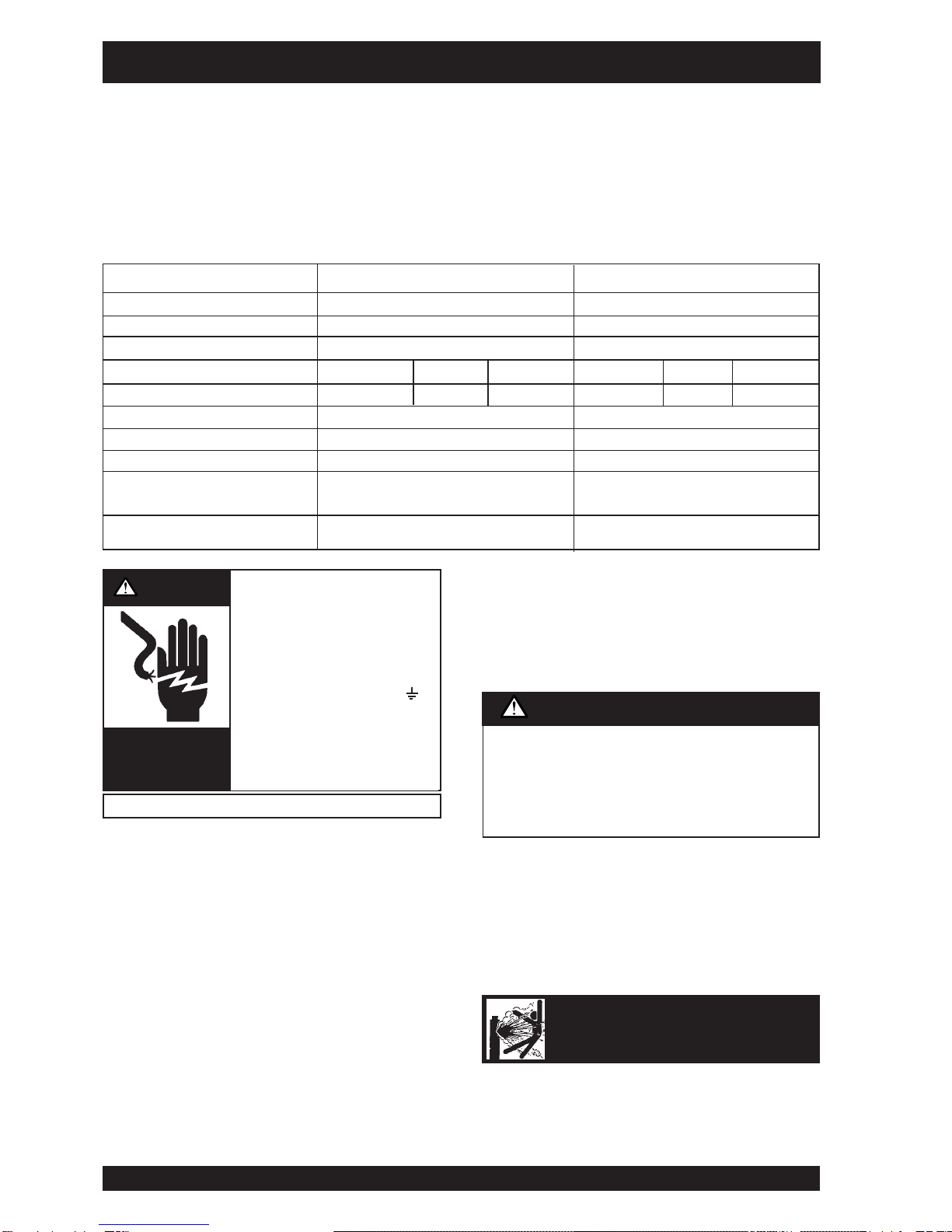
• Turn the input power off at
the disconnect switch
before installing or servicing
this machine.
• Do not touch electrically “hot”
parts such as output terminals
or internal wiring.
• Connect grounding screw ( )
to a good earth ground.
• Do not operate with covers
removed.
• Turn power switch “off” before
connecting or disconnecting
cables or other equipment.
PRODUCT DESCRIPTION
The Maxmig 250i is a fully integrated semi-automatic Constant Voltage DC arc welding machine. The Maxmig 210R offers a remote wire
feeder and a separate Constant Voltage DC arc welding machine. They combine a solid state power source with electronically controlled
wire feeding equipment.
Excellent arc characteristics are provided for both gas shielded and self shielded welding within its current range.
Standard features include a spot timer, gas purge facilities, a dual position 2 or 4 step trigger interlock, a Maxmig 150 MIG gun, a
regulator/flowmeter and gas hose, ground cable assembly (3m on the Maxmig 210i and 5m on the Maxmig 210R) a 3m long input lead
and an undercarriage on which a gas cylinder can be mounted.
WARNING
HIGH
VOLTAGE
can kill
Only qualified personnel should install or service this equipment.
CYLINDER may explode
if damaged
Model Maxmig 210i Maxmig 210R
Part No. 05-3210 (Integrated) 05-4210 (Remote)
Maximum Open Circuit Voltage 46V 46V
Output Current Range up to 210A up to 210A
Duty Cycle 25% 34% 100% 25% 34% 100%
Rated Output 210A/24.5V 180A/23V 120A/20V 210A/24.5V 180A/23V 120A/20V
Rated Input 240V single phase 50Hz 15 amps 240V single phase 50Hz 15 amps
Wire Speed Range 1-20 m/min 1-20 m/min
Weight (complete with u/c) 88 kg 107 kg
H x W x L (mm) Over lift
bail, cylinder tray & wheels 775 x 525 x 885 mm 1129 x 525 x 885mm
Operating Temperature -20˚C to 40˚C -20˚C to 40˚C
Specifications
Never connect the green/yellow conductor to any of the
active supply lines from the mains. This conductor is to
earth the machine as required by Electrical Regulations.
Once the above has been followed the machine can be
plugged into the mains outlet.
CAUTION
IMA 578BLA Maxmig 210 Page 7
1. Set gas cylinder on rear platform of the machine. Hook
chain in place to secure cylinder to rear of welder.
2. Remove the cylinder cap. Inspect the cylinder valve for
damaged threads, dirt and dust. For cylinders having an
external thread fitting, remove any dust and dirt from the
threads with a clean cloth.
DO NOT ATTACH THE REGULATOR/FLOWMETER IF
CYLINDER VALVE IS DAMAGED! Inform your gas
supplier of this condition.
3. Stand to one side away from the outlet and open the
cylinder valve for an instant. This blows away any dust or
dirt which may have accumulated in the valve outlet.
4. Inspect the regulator/flowmeter for damaged threads and
seals, dirt and dust. Remove dust and dirt with a clean
cloth.
DO NOT USE THE REGULATOR/FLOWMETER IF
DAMAGE IS PRESENT! Have an authorised repair station
repair any damage.
5. Attach the regulator/flowmeter to the cylinder valve and
tighten the union nut(s) securely with a spanner.
6. Attach the inlet gas hose to the outlet fitting of the
regulator/flowmeter, and tighten the union nut securely
with a spanner.
7. Before opening the cylinder valve, turn the regulator
adjusting knob counter-clockwise until the adjusting spring
pressure is released.
8. Open the cylinder valve slowly a fraction of a turn. When
the cylinder pressure gauge pointer stops moving, open
the valve fully.
9. The regulator/flowmeter is adjustable. Set it for the flow
rate recommended for the procedure and process being
used before starting to weld.
1.4 Gun and Cable
The Maxmig 150 3m Ergonomic MIG gun and cable
provided with the machine has a factory fitted 0.6-1.0mm
liner and a 0.9mm contact tip.
1. Lay the cable out straight.
2. Make sure all pins on the gun cable connector are
aligned with the proper mating sockets on the front
panel gun connector and then join the connectors and
tighten the hand nut on the gun cable connector.
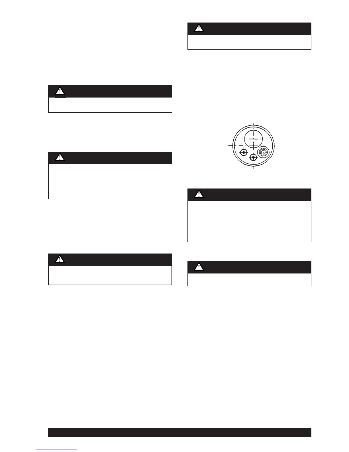
Note: If a gun and cable other than the supplied gun is to
be used, it must conform to standard European-style
connector specifications. See diagram under.
The gun trigger switch must be capable of switching 10
milliamps at 60 volts DC—resistive.
1.5 Output Polarity Connection
The integrated machines are shipped from the factory
connected electrode (+)ve. This is the normal polarity for
GMA welding. The gun polarity can be changed by placing
the flexible lead protruding from the front of the machine to
the required output stud, eg. for electrode (-)ve, connect
the lead to the (-)ve output stud.
The remote wire feeder machines are connected to the
power source via a control/electrode/gas cable assembly.
The electrode cable is connected to the required output
stud. The control cable connects to the plug in the front
panel of the power source.
Connect the work lead to the other output stud.
Gas under pressure is explosive. Always keep gas
cylinders in an upright position and always keep chained
to undercarriage or stationary support. Refer “Safety in
Welding and Cutting” - ANSI Standard Z49-1 and WTIA
Technical Note 7 available from the Welding Technology
Institute of Australia.
WARNING
Never stand directly in front of or behind the
regulator/flowmeter when opening the cylinder valve.
Always stand to one side.
WARNING
The gun trigger switch connected to the gun trigger
control cable must be a normally open, momentary
switch. The terminals of the switch must be insulated
from the welding circuit. Improper operation of, or
damage to, the machine might result if this switch is
common to an electrical circuit other than the machine
trigger circuit.
CAUTION
Turn the welder power switch off before installing gun and
cable.
WARNING
Turn the welder power switch off before changing polarity.
WARNING
Be sure to keep your face away from the valve outlet
when “cracking” the valve.
WARNING
Page 8 Maxmig 210 IMA 578BLA
2. OPERATING INSTRUCTIONS
2.1 Duty Cycle
The machine is rated at the following duty cycles:
(1) Based on 10 min. time period (i.e., for 25% duty cycle, it is
2.5 minutes actual welding and 7.5 minutes with no welding
output, but with the input power remaining on keeping the
cooling fan operative.)
2.2 Control Panel
a) Power Switch
The mains power switch is incorporated in the “coarse”
output voltage control rotary switch. In the “0” positions the
input mains power is switched off.
b) Pilot Light
This light illuminates when the input mains power is
switched on.
c) Volts Control
The output voltage is controlled by two rotary switches.
One rotary switch provides two “coarse” voltage settings
as well as switching the mains power on. The other rotary
switch provides the user with a selection of eight “fine”
voltage settings. The selection between these two
switches allows the user to select any one of sixteen
welding voltages.
The approximate weld voltages for the switch positions
are:
d) Wire Feed Speed Control *
Use this control to adjust the speed at which the electrode
wire feeds when welding. This is in effect a current control
as the power source will deliver the current necessary to
melt the wire. The higher the speed, the more current will
be required. Wire feed speed range is approximately 1 to
20 meters/min (40 to 790 inches/min.).
Operation of the gun trigger switches the wire feed motor
on and off, depending upon the mode setting. The wire
feed motor is dynamically braked to minimise wire overrun
after welding has ceased.
Welding voltage is available immediately the gun trigger is
operated, but when welding is stopped there is a factory
set delay of approximately 1/2 sec. after wire feed has
stopped to allow the electrode to burn back slightly and
prevent sticking in the crater.
e) Spot Welding *
In spot welding mode welding takes place for a pre-set
time and then stops automatically. Welding time is
adjustable between 0.5 sec. and 4 sec. by operation of the
spot weld control on the front panel. There is a positive
click in the extreme anti-clockwise position to indicate that
the spot weld feature is “off”.
*Mounted on machine control panel for Integrated units.
Mounted on remote wire feeder for Remote units.
Duty Cycle(1) Amps Volts
25% 210 24.5
34% 180 23
100% 120 20
Coarse Fine Volts Coarse Fine Volts
1 1 13.0 2 1 18.0
1 2 13.5 2 2 19.0
1 3 14.0 2 3 20.0
1 4 14.5 2 4 21.0
1 5 15.5 2 5 22.0
1 6 16.0 2 6 23.0
1 7 17.0 2 7 24.0
1 8 17.5 2 8 25.5
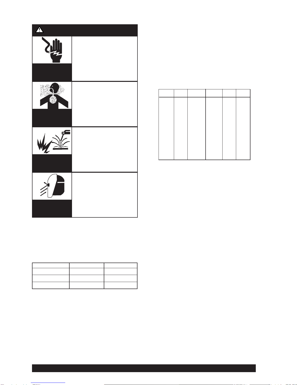
WARNING
ELECTRIC
SHOCK
can kill
FUMES AND
GASES can be
dangerous
WELDING SPARKS
can cause fire
or explosion
ARC RAYS
can burn.
• Do not touch electrically live
parts or electrode with skin or
wet clothing.
• Insulate yourself from work
and ground.
•Always wear dry insulating
gloves.
• Keep your head out of fumes.
• Use ventilation or exhaust to
remove fumes from breathing
zone.
•Keep flammable material
away.
• Do not weld upon containers
which have held
combustibles.
• Wear eye, ear and body
protection.
IMPORTANT SAFETY NOTE: In 2T mode {refer 2.2 (h)}, this
DC Constant Voltage wire welder provides “COLD” electrode
when the gun trigger is not operated. Conversely, the output
terminals are “LIVE” when the gun trigger is “activated” when
pressed in 2T mode, or triggered on in 4T mode.

IMA 578BLA Maxmig 210 Page 9
f) Gas Purge *
Use the gas purge push button to operate the gas solenoid
to purge air from the hose after connecting a new gas
cylinder. Gas purge will only operate while the button is
held in.
g) Wire Inch *
Use this push button to operate the wire feed motor and
“cold” inch the wire.
h) 2T/4T Operation *
A two position switch on the front panel provides two
modes of operation of the gun trigger. In 2T mode, the gun
trigger is pressed to start welding and released to stop.
In 4T mode, pressing the gun trigger only operates the gas
solenoid, allowing shielding gas to flow. Releasing the
trigger activates the contactor which starts the wire feed
motor and connects welding current to the wire so that
welding may commence. To stop welding, the trigger must
again be operated; pressing it stops the wire feed,
activates the burn back time delay and opens the
contactor after the pre-set burn back time. Releasing the
trigger stops the gas flow.
To recommence welding, the above cycle must be
repeated.
i) Over temperature light
Indicates that the thermostats have operated to protect
unit from over temperature.
*Mounted on machine control panel for Integrated units.
Mounted on remote wire feeder for Remote units.
3.Setting Up for Welding
The following items are required:
1) A reel of wire of suitable size and type .
2) A suitable gun and cable assembly with a “Euro”
connector and the correct tip and, if necessary gas
nozzle for the consumable being used. (A Maxmig 150
MIG gun is supplied).
3) Correct drive rolls for the wire size and type to be used.
The wire feeder is supplied with a 0.9/1.2mm hard wire
feed roll as standard; drive rolls for other types and
sizes are available as spare parts. (see table on page
10).
4) A work return cable and clamp.(supplied)
5) Normal welding accessories including helmet or hand
shield with suitable lens, gloves etc.
6) If a gas shielded process is to be used, a cylinder of
appropriate gas is required. (Regulator/flowmeter and
hose are supplied.) If gas shielding is required, connect
the gas hose.
Remember that gas cylinders may explode if damaged, so
ensure that all gas cylinders are securely mounted.
Ensure that the correct type and size wire feed rolls are fitted. In
replacing wire feed rolls, ensure that the key and keyway are
correctly positioned and tighten the knurled locking screw
securely.
Fit a spool of appropriate wire onto the 50mm spool hub so that,
for the integrated model, as wire is fed the spool turns anti-
clockwise when looking at the spool. For the remote unit, the unit
spool must turn clockwise as the wire is fed. Carefully release
the end of the wire from the spool ensuring that the released end
is held to stop the wire from unravelling. Cut off the end kink to
give a smooth straight end of wire.
Obtain a gap between the wire feed roll and the pressure roll by
lifting the cam latch. Feed the wire end into the guide tube,
between the drive rolls, and into the “Euro” connector guide until
it protrudes about 20mm out of the front of the “Euro” connector.
Close the drive rolls by lowering the cam latch ensuring the rolls
firmly hold the wire. Adjust the tension so that wire feeds
smoothly. Do not overtighten.
Fit the gun and cable assembly onto the “Euro” connector by
slipping the end of wire into the cable wire hole. Tighten the
“Euro” connector lock ring.
Activate the power source, set the wire feed speed to 4 on the
dial and press the wire inch push button. The wire feed roll
should turn, feeding the wire further up the gun and cable
assembly.
Ensure there are no kinks or sharp bends in the gun cable and
hold the wire inch button until the wire emerges from the gun. It
is good practice to remove the tip when first feeding a new coil of
wire, then refitting over the wire and tightening.
Cut off the end of the wire leaving 10mm to 15mm stick-out.
Select required polarity. See Section 1.5 - Output Polarity
Connection.
4.Welding
Put into 2T mode.
Select the output voltage required to suit the job by setting the
coarse and fine rotary switches.
Before beginning welding, ensure the wire protrudes from the
gun tip by approximately 10-15mm. Ensure welding shield and
other protective clothing are in place. Present the protruding
electrode just off the work. Maintain a steady grip on the gun,
protect your eyes with a welding shield, then press and hold the
gun trigger to create the arc.
If it is necessary to adjust the weld voltage, stop welding before
changing either or both of the rotary switches.
Adjust the wire feed speed as necessary to suit the job. At the
completion of the weld, release the gun trigger and pull the gun
away from the work to stop the arc.
4T mode should only be used for long welds by experienced
operators.
Integrated machine
When the gun trigger is pressed (2T mode) or pressed
and released the first time (4T mode), the wire is at
welding voltage. The wire should never touch the case of
the wire feeder. If it does, it is possible for the wire to arc
to the case.
Any wire overrun should be avoided.
WARNING

Page 10 Maxmig 210 IMA 578BLA
Changing Electrode Size and Type
When changing the electrode size or type, ensure the wire feed
roll is the correct size and type for the electrode. Wire feed rolls
have two grooves each of different sizes. Ensure the roll is
located by the key and keyway and firmly secured by knurled
screw.
When changing to aluminium welding a new drive roll, cable liner
and contact tip should be used.
Also check electrode polarity, as different processes may require
different polarities.
Adjust Spool Tension
The spool should stop rotating when the wire feed roll stops.
Overrun of the spool can cause the coil of wire to unravel. The
spool hub should be tensioned so that it neither drags nor
overruns. The tension can be set by adjusting the large nut
inside the hub with a tube spanner.
*The Maxmig 150 gun, with a 1.2mm tip and liner will be required for 1.2mm
wires.
5.MAINTENANCE
Safety Precautions
Routine Maintenance
General
In extremely dusty locations, dirt may clog the air passages and
cause the welder to run hot. Blow dirt out of the welder with low-
pressure air at regular intervals to eliminate excessive dirt and
dust build-up on internal parts.
The fan motors have sealed ball bearings which require no
service.
Welding Thermal Overload Protection
The Maxmig 210 has built-in protective thermostats that respond
to excessive temperature. They open the wire feed and welder
output circuits if the machine exceeds the maximum safe
operating temperature because of a frequent overload, or high
ambient temperature plus overload. The over temperature light
on the control panel glows if thermostats open. The thermostats
automatically reset when the temperature reaches a safe
operating level.
Gun and Cable Maintenance
Cable Cleaning
Clean cable liner after using approximately 150kg of electrode.
Remove the cable from the wire feeder and lay it out straight on
the floor. Remove the contact tip from the gun. Using an air hose
and approx. 350 kPa (50psi) pressure, gently blow out the cable
liner from the gas diffuser end.
Flex the cable over its entire length and again blow out the cable.
Repeat this procedure until no further dirt comes out.
Gun Tips and Nozzles
The gun tip should be replaced when worn. Replace with the
correct size for the wire type and diameter. Too large a tip for the
electrode wire will cause arcing within the gun cable and possible
jamming of the wire within the cable .
Remove spatter from inside of gas nozzle and from tip after each
10 minutes of arc time or as required.
Drive Rolls and Guide Tubes
After every coil of wire, inspect the wire drive mechanism. Clean
it as necessary by blowing with low pressure compressed air. Do
not use solvents for cleaning the idle roll because this may wash
the lubricant out of the bearing. All drive rolls are stamped with
the wire sizes they will feed. If a wire size other than that
stamped on the roll is to be used, the drive roll must be changed.
Avoiding Wire Feeding Problems
Wire feeding problems can be avoided by observing the following
gun handling procedures:-
1. Do not kink or pull gun cable around sharp corners.
2. Keep the gun cable as straight as possible when welding
or loading electrode through cable.
3. Keep gun cable clean by following maintenance
instructions.
4. Use only clean, rust-free electrode. LiquidArc electrode
has proper surface lubrication.
5. Replace contact tip when the arc starts to become
unstable or the contact tip end is fused or deformed.
Input Lead
If the supply cord is damaged, it must be replaced with a special
cord, Part No. AS2373-2.
Excessive pressure at the start may cause dirt to form a
plug.
CAUTION
Part No. Size (mm) Use with
AS4449-9 0.6 - 0.8 Hard Wire
AS4449-1 0.8 - 1.0 Hard Wire
AS4449-2 1.0 - 1.2 Hard Wire*
AS4449-5 0.8A - 1.0A Aluminium Wire
AS4449-10 1.0A - 1.2A Aluminium Wire*
AS4449-3 0.8 - 1.0 Cored Wire
Available Drive Rolls
WARNING
ELECTRIC
SHOCK
can kill
• Have an electrician install and
service this equipment.
• Turn the input power off at the
fuse box, or unplug input lead
before working on equipment.
• Do not touch electrically hot
parts.

IMA 578BLA Maxmig 210 Page 11
GROUND TEST PROCEDURE
Warning: This procedure is only suitable for
applications using DC mega testers up to 500V.
Note: This procedure is for ‘machines as built’ many
modifications could have taken place over the life of a particular
machine, so details of this procedure may need to be ‘adjusted’
to suit these modifications.
For prompt service contact your local authorised LiquidArc Field
Service Shop.
The insulation resistance values listed below are from Australian
Standard AS1966.1
If any problems are encountered refer to your nearest authorised
LiquidArc Field Service Shop.
1. Disconnect input cable from power supply.
2. Disconnect gun assembly and work cable.
3. Remove the RHS side panel from power source and LHS
from traveller (if applicable).
4. Jumper the two (2) AC terminals and the (+)ve terminal of
the bridge rectifier, (a total of three (3) places).
5. Disconnect the PCB plug and insert a 20 way shorting
plug into the harness.
6. Switch the ‘fine’ control rotary switch to position ‘one’ (1)
and switch the ‘course’ control toggle switch to position
(1).
7. Primary Test: Connect one lead of the mega tester to the
frame of the machine and the other lead to the Active
terminal of the input plug. Apply the test. (Min. resistance
1MΩ)
8. Welding Circuit Test: Connect one lead of the mega tester
to the frame of the machine and the other lead to the (+)ve
output stud. Apply the test. (Min. resistance 1MΩ)
9. Welding Circuit to Primary Test: Connect one lead of the
mega tester to the (+)ve output stud and the other lead to
the Active terminal of the input plug. Apply the test. (Min.
resistance 10MΩ)
10. Transformer Thermostat Test: Connect one lead of the
mega to the frame of the machine and the other lead to
lead No 42 (transformer thermostat). Apply the test. (Min.
resistance 1MΩ)
11. Remove all jumpers and reconnect all leads and plugs.
12. Refit all panel work previously removed.
ELECTRIC SHOCK CAN KILL
Changing Settings for Wire Burnback and
Motor Acceleration
If Electrode Wire Burnback or Motor Acceleration need to be
altered from factory settings, because of the welding procedure
being used, locate the PCB in the power source or in the
traveller.
On the PCB there is a trimmer labelled ‘R.T.S.’, this trimmer
controls the wire burnback time. It adjusts a time period from
when the drive motor stops until the power source and gas
solenoid are switched off. [Approximately 0.1 seconds (when
fully counter-clockwise) to approximately 1.1 seconds (when fully
clockwise)]. Factory setting is mid-position.
Another trimmer on the PCB is labelled ‘Rampa’, this trimmer
controls the acceleration rate of the drive motor from stationary
to the set wire feed speed. Maximum acceleration when fully
counter-clockwise to minimum acceleration when fully clockwise.
This is particularly important when welding aluminium wire. The
factory setting is fully clockwise.
Procedure for Replacing PC Boards
Before replacing a PC board suspected of being defective,
visually inspect the PC board in question for any visible damage
to any of its components and conductors on the back of the
board.
1. If there is no visible damage to the PC board, install a new
one and see if this remedies the problem. If the problem is
remedied, reinstall the original PC board to see if the
problem still exists. If the problem no longer exists with the
old PC board:
a. Check the PC board harness connector pins for
corrosion, contamination, or looseness.
b. Check leads in the plug harness for loose or
intermittent connection.
2. If PC board is visibly damaged, before possibly subjecting
the new PC board to the same cause of failure, check for
possible shorts, opens or grounds caused by:
a. Damaged lead insulation.
b. Poor lead termination, such as a poor contact or a
short to adjacent connection or surface.
c. Shorted or open motor leads, or other external leads.
d. Foreign matter or interference behind the PC board.
3. If PC board is visibly damaged, inspect for cause, then
remedy before installing a replacement PC board.

Page 12 Maxmig 210 IMA 578BLA
TROUBLESHOOTING
WARNING
ELECTRIC
SHOCK
can kill
•Have an electrician install and
service this equipment.
•Turn the input power off at the
fuse box and unplug the machine
before working on equipment.
• Do not touch electrically hot parts.
Problem
Rough wire feeding or
wire not feeding but drive
rolls turning.
Variable or “hunting” arc.
Poor arc striking with
sticking or “blast offs”,
weld porosity, narrow and
ropey looking bead, or
electrode stubbing into
plate while welding.
Tip seizes in diffuser.
Possible Cause
Gun cable kinked and/or twisted.
Wire jammed in gun and cable.
Incorrectly fitted drive roll
Drive roll loose.
Gun cable dirty.
Worn drive roll.
Electrode rusty and/or dirty.
Worn nozzle or cable liner.
Partially flashed or melted contact tip.
Incorrect idle roll pressure.
Wrong size, worn and/or melted contact tip.
Worn work cable or poor work connection.
Loose electrode connections.
Wrong polarity.
Improper procedures or techniques.
Improper gas shielding
Tip overheating due to prolonged or
excessive high current and/or duty cycle
welding.
What To Do
Inspect gun cable and replace if necessary.
Remove wire from gun and cable - feed in new wire.
Note any obstructions in gun and cable. Replace gun
and cable if necessary.
See Wire Drive Roll Section in this manual for proper
installation of drive roll.
Remove, clean, install and tighten.
Clean cable or replace liner.
Replace.
Replace.
Replace.
Replace contact tip.
Set idle roll pressure.
Replace tip - remove any spatter on end of tip.
Inspect - repair or replace as necessary.
Be sure electrode lead is tight, gun cable tight in wire
feeder contact block, gun nozzle and gun tip tight. All
work lead connections must be tight.
Check connection at output studs for polarity
required by welding process.
See “Gas Metal Arc Welding Guide”(GS100).
Clean gas nozzle. Make certain that gas diffuser is
not restricted. Make certain that gas cylinder is not
empty or turned off. Make certain gas solenoid valve
is operating and gas flow rate is correct.
Remove gun liner and check rubber seal for any sign
of deterioration or damage. Be sure set screw in
brass connector is in place and tightened against the
liner bushing.
Do not exceed current and duty cycle rating of gun.
A light application of high temperature antiseize
lubricant may be applied to tip threads.

IMA 578BLA Maxmig 210 Page 13
Possible Cause
Defective wire feed motor or wire drive
control PC board.
Defective wire drive control PC board.
Control cable not connected.*
Overtemperature protection circuit actuated
due to overload or short. Overtemperature
light should be illuminated.
Faulty gun trigger switch or damaged control
cable connected to gun trigger.
Defective control PC board.
Defective contactor
Improper settings for wire feed speed and
volts.
Faulty rotary switch either coarse control
(on/off) or fine control.
Faulty pilot transformer.
Faulty main transformer.
Faulty rectifier.
Faulty choke.
What To Do
Measure the voltage between Red motor
lead (54) and the Green motor lead (53)
when the wire inch push button is
depressed. If this voltage is over 10V DC,
replace the wire feed motor. If no voltage is
registered, replace the wire drive PCB.
(Refer PCB replacement procedure at end of
Troubleshooting Guide).
Replace PCB. (Refer PCB replacement
procedure at end of Troubleshooting Guide).
Connect cable to welding power source.
Allow machine to cool down and reduce on
time and/or wire feed speed.
Repair.
Refer Procedure for Replacing PC Boards at
end of Trouble Shooting Guide, if no fault is
detected in trigger-thermostat circuit.
Replace defective contactor
Set controls correctly.
Replace rotary switch.
Replace.
Replace.
Replace
Replace.
Problem
No wire feed, although arc
voltage is present.
No control of wire feed.
No wire feed and no arc voltage.
Pilot light indicates input power
to machine.
Poor welding characteristics
and/or cannot obtain full rated
output as per nameplate.
* For Remote M/Cs only.
TROUBLESHOOTING

Page 14 Maxmig 210 IMA 578BLA
NOTES

IMA 578BLA Maxmig 210 Page 15
Sub Assembly
Item No. 1 2 3 4 5 6
Sub Assembly
Page Name
Machine Part List No. AP-82-C AP-82-D AP-93-D AP-103-[ ] AP-82-W IMA578BLA
Description Code No.
1483 05-2210 1 1 AP-103-Z AL2597 IMA578ALA
1539 05-3210 2 2 1 AL2597 IMA578ALA
1641 05-3210 2 2 AP-103-Z AL2597 IMA578ALA
70008 05-3210 2 2 AP-103-E AL2597 IMA578BLA
AP-82
Operative: 4.7.03
Supersedes: 28.10.98
MAXMIG 210i
PARTS LIST AP-82
Do not use this Parts List for a machine if its code number is not listed. Contact the Service Department for any code
numbers not listed.
Numbers in the table below indicate which column to use in each parts list for each individual code number.
Refer Page 21 for Maxmig 210R
Refer Page 27 for Maxidrive 2R
General Assembly
Front Panel Assembly
Specification No.
MIG Torch
Wiring Diagram
Instruction Manual
Drive Plate Assembly
Page 16 Maxmig 210 IMA 578BLA
AG1394 for Code 1483
AG1376-1 for Code 1539
Ref: AG1394 (28.10.98)
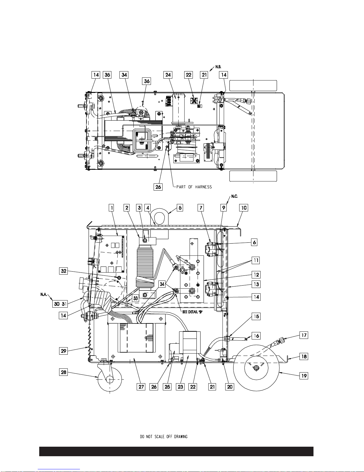
General Assembly
Maxmig 210i
AP-82-C
Operative: 4.7.03
Supersedes: 28.10.98

IMA 578BLA Maxmig 210 Page 17
# Indicates a change this printing.
* Items not illustrated.
ITEM DESCRIPTION PART NO. QTY. 123456789
1 Motor Control PCB AS4212-4SP 1 X X
2 Choke Assembly AM3484 1 X X
3D* Insulating Tube T7028-226 2 X X
3E* Insulating Washer AT2882 4 X X
4 Liftbale Seal S12934 1 X X
5 Bulkhead Assembly AL2491 1 X X
7 Fan Motor AS4233-1 1 X X
9 Fan Blade AM3285 1 X X
Fan Blade (code 1641 and above) AM3285-1 1 - X
10 Roof and Door Assembly AG1343U 1 X -
Roof and Door Assembly AG1343-1 1 - X
11 Fan Shroud and Bracket Assembly AM3450-1 1 X X
12 Rectifier AL2480-2 1 X X
13 Rear Panel AL2486 1 X X
14 Rubber Buffer AS4404-1 2 X -
Magnetic Catch AS4532 2 - X
15 Cord Grip Grommet AT3764-1 1 X X
16 Input Lead AS2373-2 1 X X
17 Gas Hose Assembly AS4150-1 1 X X
18 Base and Axle Assembly AM3279-2 1 X X
19 Wheel AS4071-1 2 X X
Axle Push Nut AT2876 2 X X
20 Gas Solenoid AM3399-1 1 X X
Brass Bard Straight Tail AT3730-3 2 X X
21 Earth Tag AT3166 1 X X
22 Terminal Block AT3070-2 1 X X
23 Auxiliary Transformer PT0052 1 X X
24 Spool Post AM3387SP 1 X X
Spacer Washer AS4482 1 X X
25 Contactor AM3423-1 1 X X
26 5/32” X 1/2” Blind Rivet AT3425-2 1 X X
27 Transformer Assembly AL2535-1 1 X X
28 4” Swivel Castor AS4070 2 X X
29 Front Panel Assembly AL2537-2 1 X -
Front Panel Assembly AL2537-4 1 - X
Top Panel Assembly AL2537-4 1 - X
30 Rotary Sw Reworked- 8 Pos AS4559 1 X X
32 Bushing T12380-2 1 X X
33 Bushing T14614-2 1 X X
35 Lead - Sec.Tap to(-) Stud NSS 1 X X
36 Thermostat T14542-1 1 X X
41* Lead Harness AG1375 1 X X
51* Side Panel AL2487U 1 X -
Side Panel AL2487-1 1 - X
52* Side and Reel Shelf AL2488U 1 X X
53* Wiring Diagram AL2597 1 X X
54* Warning Decal AS4244 1 X X
55* Warning Decal AT3378 1 X X
56* Ground Cable Assembly AS4092-4 1 X X
58* Regulator/Flowmeter 94001310 1 X X
59* Chain AT3873 1 X X
60* Warning Tag AS3234 1 X X
62* Literature AL1369-119 1 X X
63* Pallet AM3288 1 X X
Use only the parts marked “X” in the column under the
heading number called for in the model index page.
AP-82-C1
Operative: 4.7.03
Supersedes: 28.10.98
Recommended Spare Parts are highlighted in bold
Nut, bolt and washer sizes are given so they may be procured locally.
Page 18 Maxmig 210 IMA 578BLA
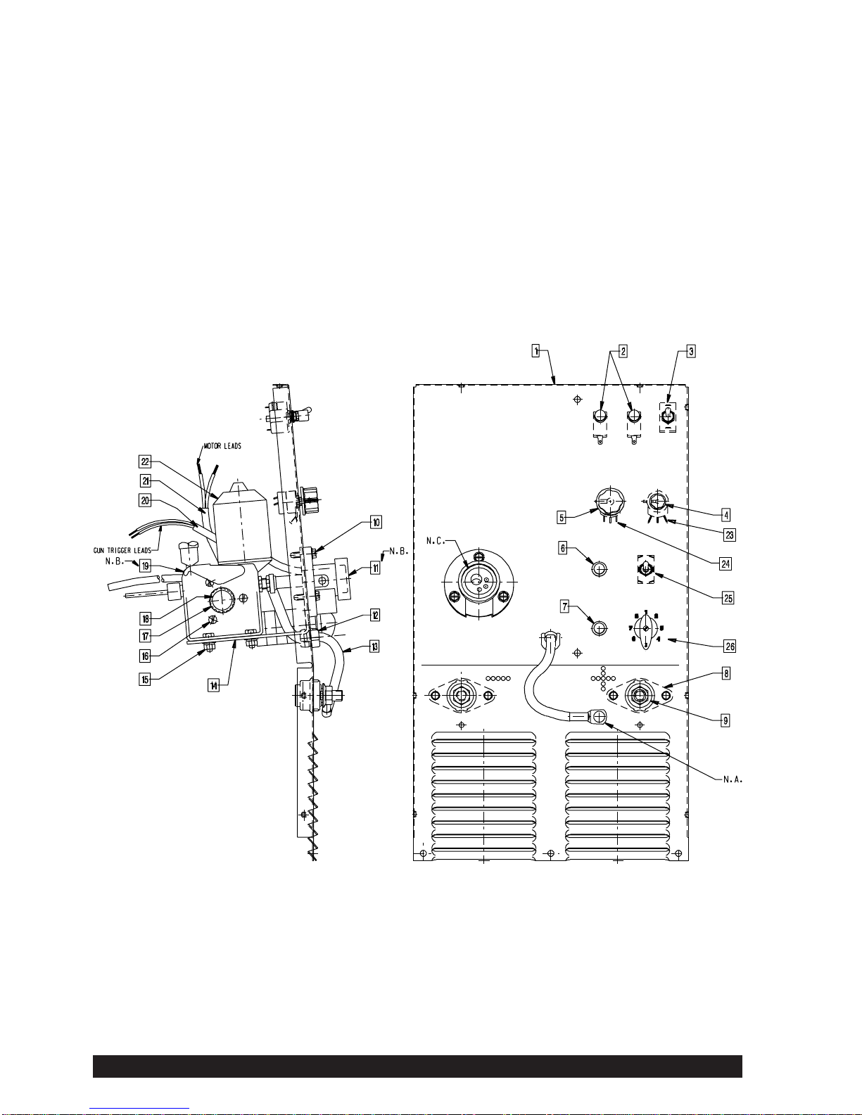
Ref: AL2537-4 (28.10.98)
Control Panel Assembly
Maxmig 210i
AP-82-D
Operative: 4.7.03
Supersedes: 28.10.98

IMA 578BLA Maxmig 210 Page 19
# Indicates a change this printing.
* Items not illustrated.
ITEM DESCRIPTION PART NO. QTY. 123456789
1 Front Panel (code 1483) AL2532-2 1 X -
Front Panel (codes 1539 and above) AL2532-3 1 - X
2 Microswitch Pushbutton AT3561-1 2 X X
3 Toggle Switch SPST T13562 1 X X
4 Knob 0.76” Spot Timer T10497 1 X X
5 Knob 1.3” Voltage T10491F 1 X X
6 Indicator - Over Temp. AT3384-1 1 X X
7 Pilot Light AS4460-1 1 X X
8 Moulded Output Stud AM2464-1 2 X X
11 Gun Adaptor AM3025-2 1 X X
12 Cord Grip Grommet AT3764-2 1 X X
13 Cable AS4462-1 1 X X
14 Wire Drive Mtg Brkt. AM3390-1 1 X -
Wire Drive Mtg Brkt AM3390-2 1 - X
17 Drive Roll 0.6 - 0.8mm Steel AS4449-9 1 X X
Drive Roll Adaptor AM3391-3H 1 X X
18 Drive Roll Cap Screw AM3391-1R 1 X X
19 Drive Plate AM3391-5 1 X X
20 Sleeving AM3058-412 1 X X
21 Sleeving AM3058-161 1 X X
22 Drive Motor AM3366-1 1 X X
23 Potentiometer 100k/SW 3A 125V AS4212-2 1 X X
24 Potentiometer 1k AS4212-1 1 X X
25 Toggle Switch DPDT AT3440 1 X X
26 Rotary Switch 8 Position 16 amp AM3388-1 1 X X
Use only the parts marked “X” in the column under the
heading number called for in the model index page.
AP-82-C1
Operative: 4.7.03
Supersedes: 28.10.98
Recommended Spare Parts are highlighted in bold
Nut, bolt and washer sizes are given so they may be procured locally.
Page 20 Maxmig 210 IMA 578BLA
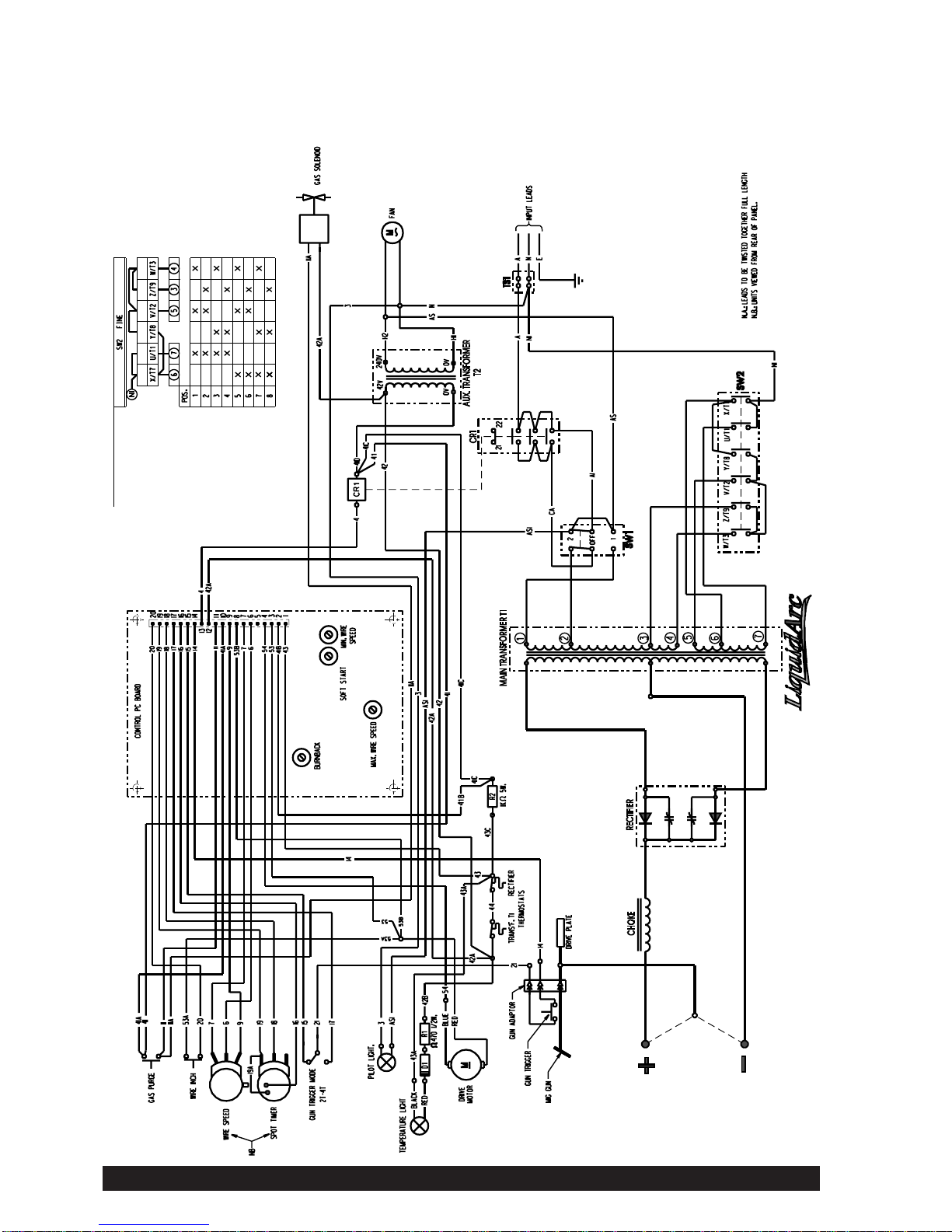
Ref: AL2597 (A23.10.96)
For Codes 1483 & 1539
Wiring Diagram
Maxmig 210i
AP-82-W
Operative: 4.7.03
Supersedes: 28.10.98
This manual suits for next models
1
Table of contents
Other liquidarc Welding System manuals

Popular Welding System manuals by other brands


GYS
GYS PROGYS 220E FV CEL manual

Lincoln Electric
Lincoln Electric Air Vantage 600X-I Operator's manual

Gude
Gude GE 145 W Translation of the original operating instructions

Truper
Truper Expert SOMU-250X manual

Miller Electric
Miller Electric Maxstar 150 STH Specifications

Lincoln
Lincoln IDEALARC DC-400 operating manual