LMS Cal Flame User manual

LTR50001006, Rev. E
1/1/16

Copyright 2016LMS. All rights reserved.
Duplication without written consent is
strictly prohibited.
Cal Flame ® is a registered trademark.
Due to continuous improvement programs,
all models, operation, and/or specications
are subject to change without prior notice.
LTR50001006, Rev. E
1/1/16
250-452
Installation / Assembly........................5
Placement and Location ............................6
Leak Testing Procedure.............................7
Liquid Propane....................................8
Propane Cylinder Enclosure ........................10
Natural Gas .....................................12
Fireplace Burner Installation .......................13
Fireplace Log Set Placement........................16
High Elevation Installation .........................17
Natural Gas Conversion............................17
Operation ................................. 19
Cleaning and Maintenance ................... 22
Replacement Parts ......................... 23
Specications ............................. 24
Limited Warranty .......................... 25
Save these instructions!
California Proposition 65 Warning:
Chemicals known to the State of
California to cause cancer, birth
defects or other reproductive
harm are found in and/or creat-
ed by the combustion of natural
gas, propane, butane and other
fuels. Always operate this unit as
described in the owner’s manual
and in well ventilated areas.
Read this before installing or operating your
new Cal Flame replace.

Safety Instructions
1
Fireplace Owner’s Manual
LTR50001006, Rev. E
www. c a l a m e b b q . c o m
Safety Instructions
What To Do If You Smell Gas
Shut off gas to the replace.•
Extinguish any open fl ame.•
Do not try to light the appliance.•
If odor continues, keep away from the appliance and•
immediately call your gas supplier or your re depart-
ment.
WARNING: Improper installation, adjustment,
alteration, service or maintenance can cause in-
jury or property damage. Read the installation,
operating and maintenance instructions thoroughly be-
fore installing or servicing this equipment.
Cal Flame replaces are designed for
outdoor use only.
Do not store combustible materials, gasoline
and any other fl ammable vapors and liquids.
A propane gas cylinder not connected for use shall not be
stored in the vicinity of this or any other appliance.
Carbon Monoxide Hazard
This appliance can produce carbon monoxide
which has no odor.
Using it in an enclosed space can kill
you.
Never use this appliance in an en-
closed space such as a camper, tent,
car, or home.

2
Safety Instructions
Fireplace Owner’s Manual
LTR50001006, Rev. E
www. c a l a m e b b q . c o m
Operation
Do not use charcoal or other solid fuel in a gas burning•
replace.
Do not operate the replace with the propane tank on, near, or •
under the hearth! This could result in re, explosion, or severe
injury.
Do not use your replace for cooking.•
In the event that a burner goes out, turn burner knobs to the full•
OFF position and let it air out. Do not attempt to use the replace
until the gas has had time to dissipate.
Keep all electrical supply cords away from the heated areas of the•
replace.
Never use the replace in windy conditions. If used in a consis-•
tently windy area a windbreak will be required. Always adhere to
the speci ed clearances listed in this manual.
When handling propane gas line and connectors, do not allow them•
to come in contact with any metal surfaces. Do not drop propane
connectors.
Propane gas sources to the replace must be regulated. Do not •
operate if regulator has been removed. Fire or explosion can oc-
cur.
Never leave the replace unattended when in use.•
Never allow clothing or other fl ammable materials come in contact •
with any hot surface until it has fully cooled. Never wear loose t-
ting or hanging garments while using your replace. Fabric may
ignite and result in personal injury.
Clothing or other fl ammable materials should not be hung from the •
appliance, or placed on or near the appliance.
When using the replace, do not touch the rock, re screen, or im-•
mediate surroundings, as these areas become extremely hot and
could cause burns.
Do not heat any unopened glass or metal container of food in the•
replace. Pressure may build up and cause the container to burst,
possibly resulting in serious personal injury or damage to the re-
place.
Never line replace with aluminum foil.•

Safety Instructions
3
Fireplace Owner’s Manual
LTR50001006, Rev. E
www. c a l a m e b b q . c o m
Maintenance and Repair
Spiders and other insects can nest in the burners and block the gas•
and airfl ow to the burner ports. This creates a dangerous condi-
tion that can result in a re from behind the valve panel. Inspect
and clean the burners periodically and follow the guidelines in the
maintenance section of this manual.
The appliance should be inspected before use and at least annually•
by a quali ed service person.
More frequent cleaning may be required as necessary. It is impera-•
tive the control compartment, burner and circulation air passage-
ways of the appliance be kept clean and free.
Any guard or other protective device removed for servicing the ap-•
pliance must be replaced prior to operating the appliance.
If it is evident there is excessive abrasion or wear of any of the•
components, if the fuel supply hose is cut or cracked, it must be
replaced prior to the appliance being put into operation.
Inspect the fuel supply connection for signs of leakage (including•
the hose for propane models) before each use of the appliance.
Unless speci cally recommended in this manual, do not repair or •
replace any part of your replace. Have a quali ed technician per-
form all service. Any repairs made by a non-LMS approved dealer
technician will void your warranty.

4
Safety Instructions
Fireplace Owner’s Manual
LTR50001006, Rev. E
www. c a l a m e b b q . c o m
Storage
When your replace is not in use, turn off the gas at the source.•
Do not store the propane cylinder in the vicinity of this or any other•
appliance when it is not being used.
This appliance can be store indoors only if it has been discon-•
nected from its fuel supply.
Store propane cylinders outdoors in a well-ventilated area out of•
reach of children. Disconnected sylinders must have threaded valve
plugs tightly installed and must not be stored in a building, garage,
or any other enclosed area.
To extend the life of your replace, protect and cover it from the •
elements when not in use. Ensure the appliance has ample time
to cool off after use and prior to installing storage cover. Damage
caused to storage cover due to heat or burns are not covered by
warranty.
Precautions Regarding Children
Never leave children unattended in the area where the replace is •
being used. Close supervision of children is necessary when any
appliance is used near children.
Do not store items of interest to children around or below the•
replace.
Never allow children to sit or stand on any part of the replace.•

Installation / Assembly
5
Fireplace Owner’s Manual
LTR50001006, Rev. E
www. c a l a m e b b q . c o m
Set-Up
You are responsible for ensuring that a natural gas line (if required)
is installed and safe for use. We recommend that a licensed contrac-
tor install your replace. Installation must conform to local codes, or
in the absence of local codes, with either the National Fuel Gas
Code, ANSI Z223.1 / NFPA54, Natural Gas and Propane Installa-
tion Code, CSA B149.1, or Propane Storage and Handling Code,
B149.2), as applicable.
To prevent re and smoke damage, remove all packaging material be-
fore operating the replace.
Installation / Assembly
Installation and service must be performed by a quali-
ed installer, service agency or your natural gas or liquid
propane gas provider.
Most cities and counties require permits for exterior construction and
electrical circuits. In addition, some communities have codes requiring
residential barriers such as fencing and/or self-closing gates on prop-
erty to prevent unsupervised access to the property by children under
the age of 5. Your dealer can provide information on which permits
may be required and how to obtain them prior to the delivery of your
equipment.

6
Installation / Assembly
Fireplace Owner’s Manual
LTR50001006, Rev. E
www. c a l a m e b b q . c o m
Placement and Location
Cal Flame replaces are designed for
outdoor use only.
Never locate this appliance in a building, garage, or any other en-•
closed room or under a sealed overhead structure, or in any type
of enclosed area such as a garage, shed, or breezeway. Keep clear
of trees and shrubs.
Do not place replace under or near windows or vents that can be •
opened into your home.
Maintain suf cient distance as to not overheat any overhead com-•
bustible material such as a patio cover.
The area surrounding your replace should be kept clean and free •
from fl ammable liquids and other combustible materials such as
mops, rags or brooms, as well as solvents, cleaning fl uids, and
gasoline.
Do not block the vents located near the base of your replace as •
gas may build up in case of leak and cause serious damage.
Do not install or operate your replace in such a manner that the •
cross ventilation openings are blocked. Fresh air must be able to
pass though installed vents to safeguard against residual gas ac-
cumulation. Failure to allow proper ventilation may cause re or
explosion.
Do not locate appliance where it can get excessively wet. Do not•
use this appliance if any part has been underwater. Immediately
call a quali ed service technician to inspect the unit and to replace
any part of the control system and any gas control which has been
underwater.
Place your replace on a fl at and stable surface in an outdoor loca-•
tion such as a patio deck.
Locate your replace adjacent to the gas supply line (liquid pro-•
pane or NG), preferably with the shortest gas line run possible.
Maintain the following clearances to combustible materials on all•
Cal Flame replaces.
Sides and back 48 inches (122 cm) (measured from side)
Top 120 inches (305 cm) (measured from hearth)

Installation / Assembly
7
Fireplace Owner’s Manual
LTR50001006, Rev. E
www. c a l a m e b b q . c o m
Leak Testing Procedure
Perform a leak test at least once a year whether the gas supply cylinder
has been disconnected or not. In addition, whenever the gas cylinder
is connected to the regulator or whenever any part of the gas system
is disconnected or replaced, perform a leak test.
As a safety precaution, remember to always leak test your replace
outdoors in a well-ventilated area. Never smoke or permit sources of
ignition in the area while doing a leak test. Do not use a fl ame, such as
a lighted match to test for leaks. Use a solution of soapy water.
Prepare a leak testing solution of soapy water by mixing in a spray1.
bottle one part liquid soap to one part water.
Make sure all the control knobs are in the OFF position.2.
Turn on the gas.3.
On natural gas systems, turn the main feed valve to the burner.
On propane systems, turn the cylinder valve knob counter clock-
wise one turn to open.
Apply the leak-testing solution by spraying it on joints of the gas4.
delivery system. Blowing bubbles in the soap solution indicates
that a leak is present.
Stop a leak by tightening the loose joint or by replacing the faulty5.
part with a replacement part recommended by the manufacturer.
Do not attempt to repair the cylinder valve if it is damaged. The
cylinder must be replaced.
Turn the control knob back to the full OFF position.6.
If you are unable to stop a leak:
Turn the control knob back to the full OFF position.1.
Shut off the gas supply to the replace and release pressure in the 2.
hose and manifold by turning the control valve one quarter turn
counter-clockwise.
On propane systems, remove the cylinder from the replace.3.
Call an authorized gas appliance service technician or an liquid4.
propane gas dealer.
Do not use the appliance until the leak is corrected.

8
Installation / Assembly
Fireplace Owner’s Manual
LTR50001006, Rev. E
www. c a l a m e b b q . c o m
Liquid Propane
Your Cal Flame replace is not provided
with a propane cylinder. If you choose to
operate your replace with propane, you
must supply your own cylinder.
Requirements
The 20 lb propane gas supply cylinder
used with propane models must be con-
structed and marked in accordance with
the speci cations for propane gas cylinders as required by the U.S.
Department of Transportation (DOT) or the CAN/CSA B339, Cylinders,
Spheres and Tubes for the Transportation of Dangerous Goods.
Manifold Pressure: For plumbed-in liquid propane installation, use
a regulator.
Supply Pressure: Maximum line pressure for plumbed-in propane is
14” W.C psi (3.5 kPa). Minimum line pressure for propane is 11” W.C.
Pressure Regulator: The unit must be used with the supplied gas
pressure regulator and hose assembly. The regulator will control and
maintain a uniform gas pressure in the manifold. The burner ori ce has
been sized for the gas pressure delivered by the regulator. Replace-
ment pressure regulator and hose assemblies must be those speci ed
in this manual.
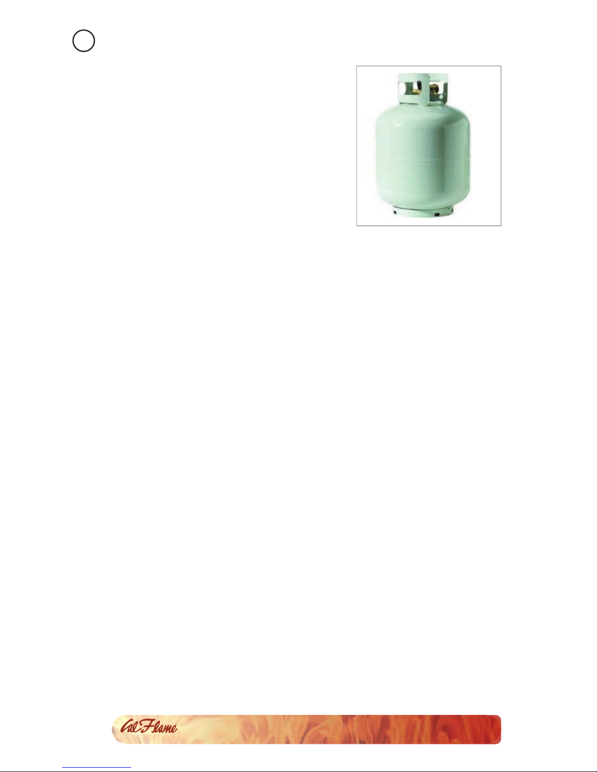
Cylinder Speci cation: Any propane gas supply cylinder used with
this replace must be approximately 12 inches in diameter and 18
inches high. The maximum fuel capacity is 20 lbs. of propane, or 5
gallons. Full cylinder weight should be approximately 38 lbs. (43.7
lbs. nominal water capacity.) Always use the cylinder dust cap on the
cylinder valve outlet during transport and when the cylinder is not
connected to the replace. The 20 lb propane gas cylinder used must
include a collar to protect the cylinder valve.
Filler Valve: If you do not have an updated ller valve on your exist-
ing propane tank, you will need to purchase one at your local hardware
store, as you will not be allowed to re ll the tank at any lling station.
Transporting Gas Cylinder: Only one cylinder should be transported
at a time. Transport cylinder in an upright and secure manner with
control valve turned off and the dust cap in place.

Installation / Assembly
9
Fireplace Owner’s Manual
LTR50001006, Rev. E
www. c a l a m e b b q . c o m
Connection
Check the rating plate to make sure the gas supply you are hooking up
to is the gas type the replace is manufactured for.
Inspect the hose shipped with the unit for damage. Never attempt to
use damaged or plugged equipment. See your local liquid propane gas
dealer for repairs. After inspecting the propane hose shipped with the
unit, connect the end with the female tting on the hose to the male
tting on the on/off gas valve at the end of the hose. Tighten ttings
using two wrenches.
When connecting the regulator assembly to the tank valve, hand tight-
en the black QCC-1 nut clockwise. DO NOT use a wrench to tighten.
See the gure below.
Purge the gas supply line of any trapped air prior to the rst ring of
the unit.
During the initial purging and subsequent lightings, NEVER allow gas
to remain in the “Open” position without rst placing and igniting the
re starter.
Be certain to mount or set the 20 lb propane gas cylinder on a fl at
surface and restrain it to prevent it from tipping.
Locate the hose out of the pathways where people may trip over it or in
areas where the hose may be subjected to accidental damage.

10
Installation / Assembly
Fireplace Owner’s Manual
LTR50001006, Rev. E
www. c a l a m e b b q . c o m
Propane Cylinder Enclosure
Cal Flame replaces do not have an enclosure for the propane cylinder.
If you build an enclosure for a propane gas cylinder, follow these rec-
ommended speci cations and follow local codes.
Ensure cylinder valves are always readily accessible. A door on the en-
closure to gain access to the cylinder valve is acceptable, provided it is
non-locking and can be opened without the use of tools.
Enclosures for propane gas supply cylinders need to be ventilated by
openings at the level of the cylinder valve and at fl oor level. This is ac-
complished by one of the following ways:
W
ID
T
H
W
ID
T
H
DEPTH
HEIGHT
Screen vents
One side openOne side open
1) One side of the enclosure is completely open.
This method has no special ventilation requirements.

Installation / Assembly
11
Fireplace Owner’s Manual
LTR50001006, Rev. E
www. c a l a m e b b q . c o m
2) All sides are completely enclosed.
This method requires at least two ventilation openings at cylinder valve
level in the side wall, equally sized, spaced at 180 degrees (3.14 rad),
and unobstructed.
Make sure each opening has a
total free area of not less then
½ square inch per pound (3.2
sq. cm/kg) of stored fuel capac-
ity and not less then a total free
area of 10 square inches (64.5
sq. cm).
Ventilation openings need to
be provided at fl oor level with
a total free area of ½ inch per
pound (3.2 sq. cm/k) of stored
fuel capacity and not less than
a total free area of 10 square
inches if the ventilation open-
ings at fl oor level are in a side
wall, make sure there are at
least two openings. The bottom
of the openings shall be at fl oor level and the upper edge no more than
5 inches (127 mm) above the fl oor. The openings need to be equally
sized, spaced at 180 degrees (3014 rad) and unobstructed.
Make sure every opening has minimum dimensions to permit the en-
trance of a 1/8 inch (3.2mm) diameter rod.
There shall be a minimum clearance of 2 inches (40.8mm) between the
lower surface of the fl oor and the propane gas supply cylinder enclo-
sure and the ground.
W
ID
T
H
W
ID
T
H
DEPTH
HEIGHT
Screen vents
One side openOne side open

12
Installation / Assembly
Fireplace Owner’s Manual
LTR50001006, Rev. E
www. c a l a m e b b q . c o m
Natural Gas
Ensure that the service supplying the replace is tted with a conve-
niently positioned shut off valve with easy access. The shut off valve
MUST NOT be inside the appliance!
Requirements
Always check the rating plate to make sure the gas supply you are
hooking up to is the gas type the replace is manufactured for.
The installation of this appliance must conform with local codes or, in
the absence of local codes, to the national fuel gas code, ANSI Z223.1a-
1998. Natural gas connection must be performed by a licensed con-
tractor or local gas company representative.
Ensure that the service supplying the replace is tted with a conve-
niently positioned shut off valve with easy access.
Installation
Connect the incoming gas supply line to the on/off gas valve of the
appliance. Make certain ALL gas connections are tight, turn the on/
off valve at the unit to the ‘on’ position and use soap and water to
test for leaks. Gas will be released at the burner for this duration. DO
NOT USE AN OPEN FLAME AND REMOVE BATTERY FROM IGNITER
BEFORE PERFORMING THIS TEST. An authorized gas appliance
installer must provide this installation service. Note that the
correct natural gas ori ce must also be installed prior to fuel line hook
up to maintain proper fl ame height and clean burn of fuel.

Installation / Assembly
13
Fireplace Owner’s Manual
LTR50001006, Rev. E
www. c a l a m e b b q . c o m
Fireplace Burner Installation
This procedure describes how to access the gas lines for installation.
Gas installation should be performed by a quali ed contractor.
Remove the right side refractory wall from the replace by remov-2.
ing one screw.
Remove the burner from1.
the hearth. It is not con-
nected and will lift out
easily.
Connect the fl ex line to 3.
the burner.

14
Installation / Assembly
Fireplace Owner’s Manual
LTR50001006, Rev. E
www. c a l a m e b b q . c o m
Slide the fl ex line and the 4.
black sparker wires into the
gap in the hearth base.
Connect the black sparker6.
wires to the valve as shown.
Reach through the gap in the5.
open right side and pull the
fl ex line and black sparker
wires.
Connect the fl ex line from the 7.
burner to the gas valve as
shown below.
Push the black gas line (for8.
propane unites) or fl ex line
(for NG units) under the
replace.
Make sure the burner has
been converted for use with
NG before connecting to a NG
source!

Installation / Assembly
15
Fireplace Owner’s Manual
LTR50001006, Rev. E
www. c a l a m e b b q . c o m
Caution! Never place or store the propane tank under
the hearth base!
Connect the LP or NG gas9.
source gas line to the gas
valve as shown below.
Replace the right side refrac-10.
tory wall.
Unscrew the push button11.
switch and insert the battery
in the starter.

16
Installation / Assembly
Fireplace Owner’s Manual
LTR50001006, Rev. E
www. c a l a m e b b q . c o m
Fireplace Log Set Placement
The log set, log grate and crushed lava rock are shipped together on
applicable models. Remove the log set and un-pack all components.
The logs are fragile -- use care when handling.
Once the replace is in position, level and safely hooked up to the
proper fuel supply, install the log grate over the plate burner.
Place the lava rock around the fl at burner plate. DO NOT place the lava
rock on the burner plate as it will affect the fl ow of the fl ame.
Place the ceramic re logs on the grate. Start by laying one log in the
center of the grate length wise.
Lay the other logs (quantity may vary by unit type) over the rst log
as shown below.
NOTE: Be sure unit is cool before touching any of the compo-
nents.
Place two logs lengthwise in the grate and position remaining logs
over them in an angled position as shown. Ensure the logs are placed
securely to avoid any movement.
18” Log Set 24” Log Set

Installation / Assembly
17
Fireplace Owner’s Manual
LTR50001006, Rev. E
www. c a l a m e b b q . c o m
High Elevation Installation
Your replace is approved for elevations up to 4,500 feet in the US and
Canada.
When installing this appliance at an elevation above 4,500 feet in the
US, it may be necessary to decrease the input rating by changing the
existing burner ori ce to a smaller size. Reduce the input by 4% for
each 1,000 feet above sea level, unless the heating value of the gas
has been reduced, in which case this general rule will not apply. To
identify the proper ori ce size, check with your local gas utility.
When installing this unit at an elevation above 4,500 feet in Canada
check with your local authorities. Consult the local gas utility for assis-
tance in determining the proper ori ce for your location.
Natural Gas Conversion
CAUTION: This service is to be completed only by an authorized gas
appliance installer. Do not attempt this conversion on your own as
there is risk of serious injury or death.
To The Authorized Gas Appliance Installer:
All Cal Flame replaces are shipped from the factory equipped to burn
on liquid propane fuel. Enclosed with this kit is a natural gas conversion
kit for converting this unit to natural gas. To perform this conversion,
follow the directions below and to the local regulation standards in
your area.
Make sure unit is not in operation and is cool enough to perform1.
this service. Shut off and disconnect propane fuel source at the
regulator end.
Carefully remove the storage cover, lava rocks and re logs. Turn 2.
unit over to access hose connections underneath.
While holding the propane ori ce in place with a wrench, unscrew 3.
brass tting on fuel inlet hose. Unscrew propane ori ce and re-
move.
Using the new brass natural gas ori ce re-install the parts in the 4.
same sequence. Turn the protective screen / air intake sleeve to al-
low a controlled amount of air fl ow through the screen and into the
fuel supply tube. Flame should have good retention. For a proper

18
Installation / Assembly
Fireplace Owner’s Manual
LTR50001006, Rev. E
www. c a l a m e b b q . c o m
burn and as a general rule, the air shutter for propane installation
should be completely open, and the air shutter for NG installation
should be mostly closed. This can be adjusted later to create a
clean and desired fl ame.
Refer to photo below for proper placement of parts. The washer5.
should insert next to the protective screen cover, then the spring is
to be aligned with the hole and nally the natural gas ori ce is to
be threaded into the end of the fuel inlet leading into the burner.
Once tight the other brass tting connection can be made from the
fuel line tted between the valve and the ori ce.
Connect natural gas supply hose (not included with kit) from sup-6.
ply source. Test for leaks.
Once the conversion is completed and leak tested, reload the re-7.
place with the lava rocks and re logs. Test the unit while in place
and verify it works properly. If fl ame from burner is not properly
adjusted you can adjust air intake by turning the protective screen
cover and air intake sleeve on the fuel supply tube.
Ori ce
assembly
for replace
burners
Other manuals for Cal Flame
2
Table of contents
Popular Indoor Fireplace manuals by other brands

Char-Broil
Char-Broil 07501316 user guide

Napoleon
Napoleon GD34-1NT Installation and operating instructions

Montigo
Montigo B34-DV-2 Installation operation & maintenance

Desa
Desa (V)PN36-A Installation and operating instructions

Faber
Faber GV36MER user manual

Majestic
Majestic NVBR36 Installation and operating manual

SEI
SEI SUSSEX BRAID FA8566 Assembly instructions

Empire
Empire DVCC32BP32N-1 Installation instructions and owner's manua

Element4
Element4 Ovation installation manual

Escea
Escea DN1150 Corner 400 Information Sheet for Builders and Architects

Ekofires
Ekofires 5010 Installation & user's instructions

Nordpeis
Nordpeis Havanna user manual