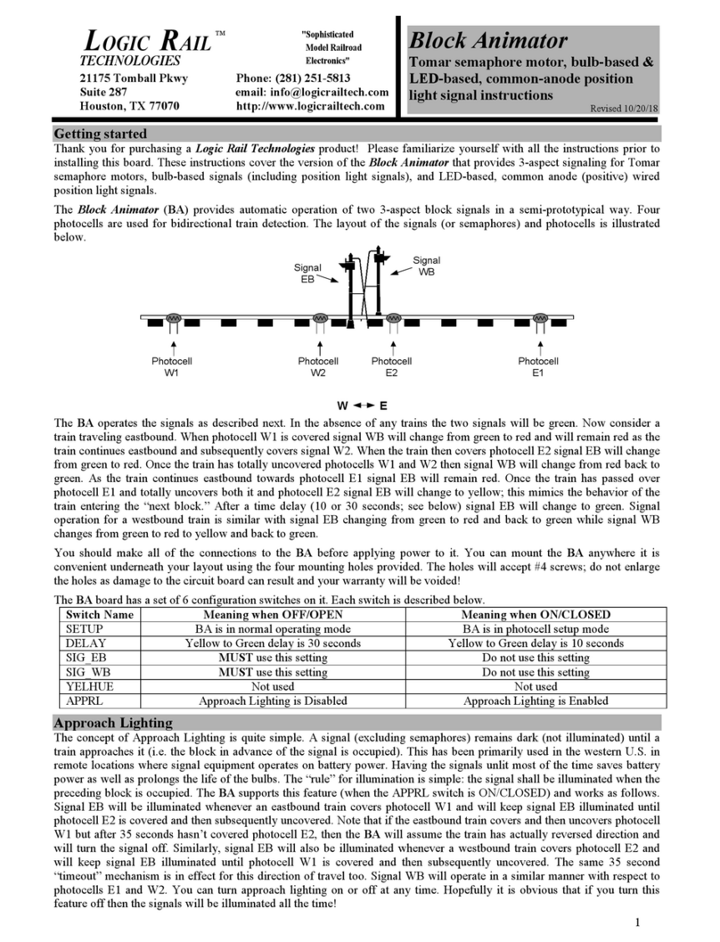
LOGIC RAIL Signal Animator User manual

L
OGIC
TECHNOLOGIES
R
AIL
"Sophisticated
Model Railroad
Electronics"
TM
21175 Tomball Pkwy Phone: 281) 251-5813
Suite 287 email: info@logicrailtech.com
Houston, TX 77070 http://www.logicrailtech.com
Signal Animator
SAD-SBCA)
Tomar semaphore motor, bulb-based &
LED-based, common-anode position
light signal instructions – IR version
Revised 2/8/13
Getting started
Thank you for purchasing a Logic Rail Technologies product! Please read all instructions prior to installing this board.
The Signal Animator provides auto atic operation of 3-color/aspect block
signals in a se i-prototypical way. An Infrared (IR) e itter and detector
are used for train detection. Detection is achieved when the IR bea fro
the e itter reflects off the underside of the train back down to the detector.
Despite the use of infrared components you could still encounter false
triggering from overhead lighting. This is usually eliminated with
angled sensor mounting and/or proper sensor sensitivity adjustment
page 4). This version of the Signal Animator must be powered from
either a 7-9V AC or 9-12V DC power source. Do NOT exceed these
limits! Whenever the sensor is activated by any portion of a train the signal
will turn red. Once the sensor is cleared the Signal Animator will delay (10
or 30 seconds; see below) and then change the signal to yellow. After
another delay the signal will be changed to green.
These instructions cover the version of the Signal Ani ator that provides 3-aspect signaling for To ar se aphore otors,
bulb-based signals (including position light signals), and LED-based, co on anode (positive) wired position light signals.
The signal outputs are “active low” (~ 0 volts when on) and capable of handling 150 A per output.
You should ake all of the connections to the Signal Animator before applying power to it. You can ount the Signal
Animator anywhere it is convenient underneath your layout using the four ounting holes provided. The holes will accept
#4 screws; do not enlarge the holes as da age to the circuit board can result and your warranty will be voided!
Tomar Semaphore Motor Connections
Connections between the Signal Ani ator and a To ar Industries’ se aphore otor are illustrated below. The input voltage
will affect the speed of the turnout otor.
SAD-SBCA-IR
DLY
C Y R G
AC GND DC +5V PC
6
7
10
5
Tomar
motor unit
conn ctor
Not us d
Figure 1 – Tomar semaphore motor connections

3-light Bulb-based Signals e.g. NJ International)
Wiring for 3-light bulb-based light signals is shown in Figure 2. You will need the current li iting resistors if the voltage
rating of the bulbs is lower than the input voltage to the Signal Ani ator. For exa ple, if the input voltage is 12V and the
bulbs are rated at 1.5V (get this infor ation fro the anufacturer of the signal) then we would suggest a resistor value of
330 oh s, 1/2W (e.g Radio Shack #RSU 271-1113). If the input voltage is equal to or slightly lower than that of the bulbs
then no resistors are needed.
C Y R G
AC GND DC +5V PC
Figure 2 – 3-light bulb-based signals
2-light Bulb-based Signals e.g. NJ International)
Wiring for 2-light bulb-based light signals is shown in Figure 3. You will need the current li iting resistors if the voltage
rating of the bulbs is lower than the input voltage to the Signal Ani ator. For exa ple, if the input voltage is 12V and the
bulbs are rated at 1.5V (get this infor ation fro the anufacturer of the signal) then we would suggest a resistor value of
330 oh s, 1/2W (e.g Radio Shack #RSU 271-1113). If the input voltage is equal to or slightly lower than that of the bulbs
then no resistors are needed.
C Y R G
AC GND DC +5V PC
Figure 3 – 2-light bulb-based signals

Bulb-based Position Light Signals e.g. NJ International)
Wiring for bulb-based position light signals is shown in Figure 4. For exa ple, if the input voltage is 12V and the bulbs are
rated at 1.5V (get this infor ation fro the anufacturer of the signal) then we would suggest a resistor value of 330 oh s,
1/2W (e.g Radio Shack #RSU 271-1113). If the input voltage is equal to or slightly lower than that of the bulbs then no
resistors are needed.
Figure 4 – Bulb-based position light signals
If your signal is an “absolute” type (that eans it has
two red bulbs for the stop position while all others are
yellow) then you will have to cut the exposed lead on the
diode D4 shown in Figure 5 on the Signal Ani ator
board. Use a pair of diagonal cutters to ake the cut. Be
sure that the two cut ends no longer touch each other by
separating the slightly. Failure to do so won’t cause
any da age but it ay cause the center yellow bulb to
illu inate when the signal is in the stop position.
C Y R G
AC GND DC +5V PC
Figure 5 – cutting diode D4 for absolute type signals
LED-based Position Light Signals common anode wiring)
The position light signal head is
shown as a circle on the right-hand
side of the drawing in Figure 6.
Within the signal head are the seven
LED “lights”; if you have a B&O
style color position light signal then
it will not have a center LED and
you will not use the C ter inal on
the Signal Ani ator. The value of
the current li iting resistors
depends upon the value of the input
voltage to the Signal Ani ator. For
a 9V AC or 12V DC input voltage
we reco end a resistor value of
330 oh s, 1/2W (e.g. Radio Shack
#271-1113). Use a higher value for
the center LED; we reco end a
value of 680 oh s (e.g. Radio Shack
#271-1117).
Figure 6 – LED-based position light signals common anode wiring)

If your signal is an “absolute” type (that eans it has two red LEDs for the stop position while all others are yellow) then you
will have to cut the exposed lead on the diode D4 shown in Figure 5 above on the Signal Ani ator board. Use a pair of
diagonal cutters to ake the cut. Be sure that the two cut ends no longer touch each other by separating the slightly. Failure
to do so won’t cause any da age but it ay cause the center yellow LED to illu inate when the signal is in the stop position.
Mounting and wiring the IR components
The IR co ponents should be ounted between the rails. Drill two 11/64” holes,
through the ballast, roadbed, and sub-roadbed. These holes should be located one tie
apart (Figure 7a) and drilled at approxi ately a 45 to 60 degree angle fro horizontal as
illustrated in the side view in Figure 7b. The benefit of ounting the at an angle is
reduced false triggering fro overhead light and increased detection reliability in s aller
scales or irregular botto s on rolling stock. For the s aller scales this drilling ay end
up hitting the ties. Take your ti e so you don’t angle the ! Insert the leads of one IR
e itter (white and black wires) into one of the holes (it doesn’t atter which one!) fro
the top of your layout. Repeat for the IR detector (blue and black wires). The tops of the
co ponents should sit no higher than the top of your ballast for opti al IR perfor ance;
in so e cases (e.g. false triggering) it ay be necessary to locate the co ponents a little
below the ballast line. You can extend the leads with si ilar (or larger) wire. We
reco end soldering and insulating these connections. We also reco end using
ter inal blocks/strips since you’ll have ultiple DC and GND connections to ake.
Once you have wired the IR co ponents and verified their operation you ay wish to
put a dab of white glue or silicone caulk where the wires exit the holes underneath the
layout. This will help to hold the co ponents in place; ake sure you don't get any
substance (e.g. ballast or glue) on the top surface of the IR co ponents as this ay
prevent the fro operating properly. In extre e cases where you ay be getting
interference fro overhead lighting you can ount the IR detector in so e plastic or
etal tubing. You can also recess the IR detector slightly below the ties and roadbed.
Figure 4a
Figure 4b
Figure 8 illustrates the wiring for the IR co ponents. The 180 oh 1 Watt resistor is included with the Signal Animator
.
WARNING: The 180 ohm 1 watt resistor may become hot to the touch –
take care so that you don’t burn yourself!
When properly wired the e itter will have a very faint red glow co ing fro it. You can also look at the e itter through a
digital ca era and see the infrared light!
For safety reasons do NOT point the IR e itter directly into your eye or stare at the
IR e itter!!!
Figure 8 – IR component wiring
You can adjust the sensitivity of the IR detector by inserting a s all screwdriver in the co ponent labeled "VR1". Turning
the screwdriver clockwise will increase its sensitivity. With a piece of rolling stock covering the sensor turn the VR1 fully
counter-clockwise and then slowly clockwise until the signal changes to red. Then slightly turn the screwdriver a little ore
clockwise. Move the rolling stock away fro the sensor and verify proper signal operation (delay, yellow, delay, green).
Signal delay
The signal color change delay can be either 10 seconds or 30 seconds. Choose the v
alue
based on your own personal preference. To select 10 seconds the ju per ust be
installed over both pins on the block "DLY"; for 30 seconds the ju per ust only cover
one pin (it doesn't atter which one). You can change this as you wish even when the
power to the Signal Ani ator is on. The two options are illustrated in Figure 9.
DLY
10 s conds
DLY
30 s conds
Figure 9 – signal delay

Power
The Signal Animator with IR requires 7-9V AC or 9-12V DC for power. Power consu ption is approxi ately 100 A
(including the signal). If you are only using a single Signal Animator then use the TWO AC ter inals to provide power
(polarity doesn’t atter). CAUTION: Most AC or DC accessory ter inals on your throttle/power pack exceed 12V and
cannot be used with the Signal Animator! However, you can use those power sources in conjunction with our 12VPSR
which will provide 12V DC. If you are using ore than one Signal Animator you can power the all fro a single 9-12V
DC source as shown in Figure 10.
Figure 10 – DC power
Multiple signals
It is possible to use two signal heads with one Signal Animator. This arrange ent could be used to i ic a standard block
signal arrange ent. The signal heads will be wired in parallel with each other (each signal ust have its own resistors where
applicable) and obviously will always show the sa e indication.
Other Applications
Please contact us if you are interested in knowing how to interlock your signal (i.e. force it to red/stop) with the position of a
turnout or if you are interested in controlling a dual head signal with two Signal Animators. You can also access this
docu entation online fro our website at http://www.logicrailtech.co /lrt_docs.ht
Troubleshooting
If your signal is not changing colors when the sensor is activated or stays red all the ti e you can perfor the following tests.
First, verify the sensor wiring and sensitivity adjust ent previously described. If the signal stays red all the ti e then disconnect
the sensor’s blue wire. After two ti e delays the signal should return to green. If it does then there is a proble with the sensor.
If your signal never changes fro green then te porarily connect a wire between the PC ter inal and the GND ter inal. The
signal should i ediately change to red. If not, then the Signal Animator board should be returned to us for test/repair. If the
signal did change to red then disconnect the te porary wire. The signal should proceed through its delay and color changes. If so
then the proble lies with the sensor.
Warranty
This product is warranted to be free fro defects in aterials or work anship for a period of one year fro the date of purchase.
Logic Rail Technologies reserves the right to repair or replace a defective product. The product ust be returned to Logic Rail
Technologies in satisfactory condition. This warranty covers all defects incurred during nor al use of this product. This
warranty is void under the following conditions:
1) If da age to the product results fro ishandling or abuse.
2) If the product has been altered in any way (e.g. soldering).
3) If the current or voltage li itations of the product have been exceeded.
Requests for warranty service ust include a dated proof of purchase, a written description of the proble , and return shipping
and handling ($6.50 inside U.S./$15.00 outside U.S. - U.S. funds only). Except as written above, no other warranty or
guarantee, either expressed or i plied by any other person, fir or corporation, applies to this product.
Technical Support
We hope the preceding instructions are sufficient for answering any questions you ight have about the installation of this
product. However, technical support is available should you need it. We would ask that you first contact your place of purchase
for assistance. If you still need further assistance then please do not hesitate to contact us. You can reach us via phone, ail and
e ail; our contact infor ation can be found on the top of page 1.
Table of contents
Other LOGIC RAIL Signal Processor manuals
Popular Signal Processor manuals by other brands

Shinkawa
Shinkawa VM-21 Series instruction manual

turck
turck MS96-11EX0-R/230VAC quick start guide

Art
Art DUALXDIRECT user manual

Altec Lansing
Altec Lansing 4024A SIGNAL PROCESSING Specifications

Extron electronics
Extron electronics MGP 641 xi Series user guide

West Mountain Radio
West Mountain Radio CLRdsp ClearSpeech operating manual