LTB MNL100 User manual

O
Op
pe
er
ra
at
ti
in
ng
g
M
Ma
an
nu
ua
al
l
N
Ni
it
tr
ro
og
ge
en
n
L
La
as
se
er
r
M
MN
NL
L1
10
00
0
Rev. 4 / October 13
LTB Lasertechnik Berlin GmbH Am Studio 2c D-12489 Berlin
Tel.: +49 (0)30 91 20 75-100 Fax: +49 (0)30 91 20 75-199
E-mail: info@ltb-berlin.de http://www.ltb-berlin.de

Operating Manual MNL 100 2
D
De
ea
ar
r
c
cu
us
st
to
om
me
er
rs
s
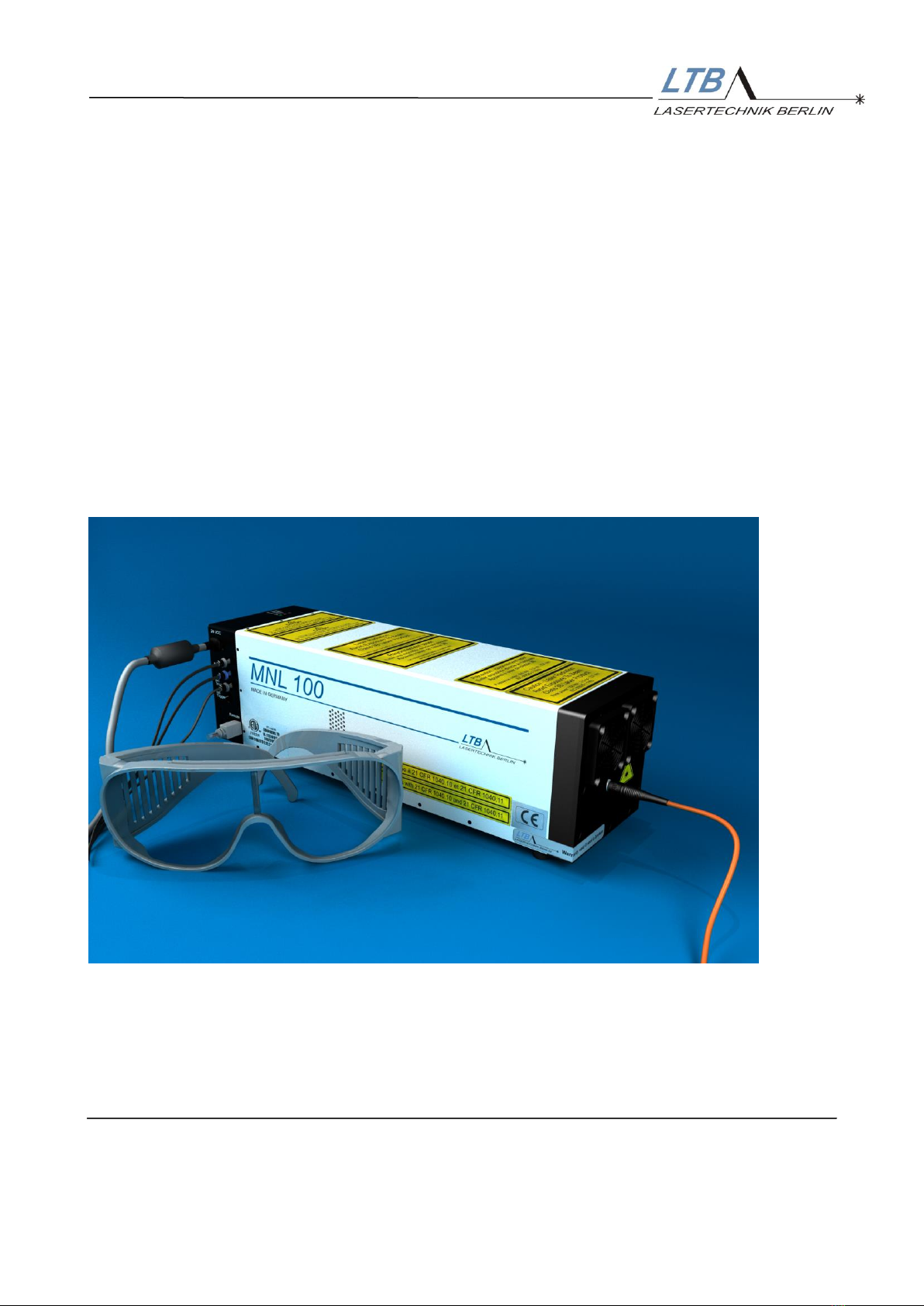
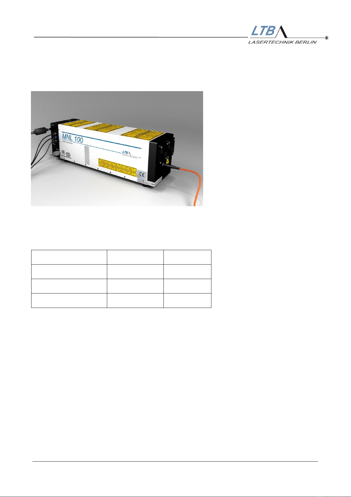
With the purchase of a laser from the MNL 100 series, you
have selected a state-of-the-art Nitrogen Laser.
The laser satisfies sophisticated needs and demanding
goals in various applications within the industrial area. The
following properties reveal the advantages of the MNL 100.
High pulse power
Minimal beam divergence
Minimal time jitter
Pulse halfwidths in the sub- and nanosecond range
Long lifetime
Low operating costs
These properties make the laser attractive for applications
where high quality, stable output and cost-effectiveness are
required.
The MNL is mainly used in
MALDI-TOF-Mass spectroscopy
Laser-induced fluorescence spectroscopy
Time-resolved spectroscopy
laser-induced plasma spectroscopy
Laser ablation
Micro-structuring
Cell dissection under the microscope
Laser acoustics
Calibration of fast sensors
Pump source of dye lasers
Amplification of ultra-short laser pulses
Technological processes like laser-induced bonding,
hardening and cleaning
Special applications in the environment and
biotechnology
The laser operates on the principle of transversal excitation.
The energy is stored in a capacitor arrangement at about
12 kV. A fast high-current discharge will be triggered by
means of a solid-state high-voltage switch thus generating
laser radiation. All laser functions are controlled and
monitored by an internal laser controller.
Your laser has been carefully tested for all operating states
with LTB’s end test program and left the firm in a good
condition.
LTB wishes you much success in working with the laser on
your projects. If this operation manual does not answer all
your questions, please do not hesitate to contact us.

Content 3
CONTENTS
1SAFETY PRECAUTIONS 5
1.1 INVISIBLE LASER RADIATION 5
1.2 HIGH VOLTAGE UP TO 12 KV 6
1.3 DANGEROUS GASES 6
1.4 LIABILITY,REPLACEMENT PARTS 6
2SYSTEM REQUIREMENTS 7
2.1 PLACE AND WAY OF INSTALLATION 7
2.2 ELECTRIC REQUIREMENTS 8
2.3 FUSES 8
2.4 LASER CONTROL,COMPUTER 9
3INSTALLATION 10
3.1 ACCLIMATIZING THE LASER 11
3.2 INSTALLING THE CONNECTION BETWEEN LASER AND COMPUTER 11
3.3 INSTALLATION OF THE USER PROGRAM MARATHONCONTROL 11
3.4 REMOTE KEY AND REMOTE SOCKET 12
3.4.1 THE EXTERNAL REMOTE CIRCUIT 12
3.4.2 CONNECTING EXTERNAL APPLICATIONS 12
4OPERATING THE LASER 13
4.1 ESTABLISH THE READINESS FOR OPERATION 13
4.1.1 REMOTE KEY 13
4.1.2 CONNECTION ESTABLISHMENT 14
4.2 STARTING THE LASER OPERATION 15
4.2.1 SWITCHING ON THE READINESS FOR OPERATION 15
4.2.2 BEAM SHUTTER 16
4.2.3 SET THE REPETITION RATE AND THE NUMBER OF PULSES 17
4.2.4 CHOOSING YOUR OPERATION MODE 19
4.2.4.1 REPETITION ON 20
4.2.4.2 BURST 20
4.2.4.3 EXT-TRIGGER 20
4.3 SWITCHING OFF THE LASER 21
4.3.1 STOPPING THE LASER OPERATION 21
4.3.2 SWITCHING OFF THE LASER 22
4.3.3 BREAK TIME AUTOMATIC 23
4.3.4 CLOSING THE BEAM SHUTTER 23
4.3.5 PROTECTING THE LASER 23

Content 4
5OPTIONAL FEATURES 24
5.1 HIGH VOLTAGE CONTROL 24
5.2 ENERGY MEASUREMENT 25
5.2.1 CALIBRATION OF THE ENERGY MONITOR 25
5.3 ATTENUATOR MODULE (IN CONNECTION WITH ENERGY MONITOR) 27
5.4 FIBER COUPLING 28
5.5 OPTICAL TRIGGER WITH ELECTRICAL OUTPUT 28
6OEM –APPLICATIONS 29
6.1 AUTOMODE OPERATION 29
6.1.1 AUTOSTANDBY30
6.1.2 TRGSTANDBY30
6.2 DIFFERENCE BETWEEN AUTOSTANDBY AND TRIGGERSTANDBY 32
6.3 DESCRIPTION OF THE BREAK TIMERS BT1 UND BT2 33
6.4 DESCRIPTION OF THE AUTO OPEN AND AUTO CLOSE FUNCTIONS 33
7SAFETY FUNCTIONS 34
7.1 TEMPERATURE MONITORING 35
7.2 ERROR MESSAGES 36
7.2.1 STATIC ERRORS 36
7.2.2 DYNAMIC ERRORS (OPERATION ERRORS) 37
7.2.3 OTHER MESSAGES 37
8APPENDIX 38
8.1 LED CODES 38
8.2 USER INTERFACE OF MARATHON CONTROL 39
8.3 INSPECTION AND MAINTENANCE 40
8.4 OPTIONAL COMPONENTS 41
8.5 WARRANTY 42
8.6 SPECIFICATIONS,TECHNICAL DATA 43
8.7 DIMENSIONS AND INTERFACES 45
8.8 FUNCTIONAL BLOCK DIAGRAM 46
8.9 SAFETY FUNCTIONS 47
8.10 DELAY AND TIME JITTER 48

Safety precautions 5
1 Safety precautions
MNL Lasers are 3B class lasers (IEC 60825-1).
Improper treatment and operation of the laser can cause
damage to your health.
Please follow carefully all the instructions in this manual.
1.1 Invisible laser radiation
The laser emits intensive invisible laser radiation in the
UV range.
Do not look into the laser beam!
Please always wear laser safety goggles appropriate to
the wavelength of 337 nm and ensure that all persons in
the vicinity of the laser also wear laser goggles during
laser operation.
For MNL lasers, you need class L6 laser goggles.
Always close the beam shutter when the laser is not
in operation.
Please observe that there are no reflecting materials in
the beam path by which the laser beam could
unintentionally be directed towards persons or sensitive
materials.
Always use beam shutters made of non-inflammable
materials in your set-up.
Always follow the safety regulations.

Safety precautions 6
1.2 High voltage up to 12 kV
A high voltage of up to 12kV is generated in the laser.
Perilously high energy amounts are also accumulated in
the capacitors of the laser. Therefore, observe the
protected earth connection of the mains. The earth
conductor connection from the laser housing to the input
of the LTB power supply of the laser is ensured.
Do not open the laser due to occurring dangerous
high voltages in the interior of the laser!
Because of high voltage circuits, the laser should never
be opened nor should any objects be put into the laser
casing openings.
1.3 Dangerous gases
The high-energetic UV radiation causes ozone. No
noxious gases are used in the laser. The cartridge has a
pressure-safe sealing.
Please observe that the laser operating room is
sufficiently ventilated.
1.4 Liability, Replacement parts
Any modification of the laser, replacement of
components or adjustment of the laser must be done by
authorized service staff.
Only components tested by LTB must be used.
Any liability and warranty lapses with the opening of the
laser or any modifications without LTB’s explicit written
consent.

System requirements 7
2 System requirements
2.1 Place and way of installation
The laser has to be operated and stored in a dry, dust-
poor and well-ventilated area.
Operation temperature
°C
+15 ... +38
Storage temperature
°C
-10 ... +60
Max. rel. humidity
%
85
Air pressure
mbar
750 ... 1300
Please make sure that the laser is not placed close to
any heat sources.
Moreover observe that the air inlet is on the side of the
beam output of the laser and must not be blocked. We
advice to replace the air inlet filters of the laser every 6 to
18 months depending on the dust concentration of the
cooling air (See also 8.3 S.40 ).
The air outlet openings on both sides of the laser cover
must stay free.
Mounting the laser may only be realized via the base
plate with the red-marked threaded holes.
(See Dimensions and interfaces, appendix 8.7)
The laser may be used in a standing position or hanging
with the beam output downwards. Other positions can be
checked on request.

System requirements 8
Please observe: only a mains that provides an
earthed conductor is to be used.
Connect the laser power supply unit only to a mains
that corresponds to the values stated on the type
label.
2.2 Electric requirements
The laser is supplied with a low voltage of 24 V DC
2.4 A. A power supply unit providing the low voltage from
the mains is part of the delivery as standard.
The mains connection values are:
100 to 240 V, 47/63 Hz, 1.1 A (see type label).
The laser power supply unit has an earthed conductor
connection that is connected to the laser housing via the
connection cable. The low voltage is off-earth, the minus
line is connected to the frame ground.
Using another power supply requires the written consent
of LTB Lasertechnik Berlin.
2.3 Fuses
The laser is equipped with resettable fuses. Their
replacement is not necessary in case of an error.

System requirements 9
2.4 Laser control, computer
Using a RS 232 interface connected to a PC or
Notebook, the laser can be operated with all functions
and settings. The last settings are stored when the laser
is switched off and are provided again as basic settings
when the laser is switched on again.
You receive with the laser an optic-electronic interface
converter to realize the connection between laser and
PC.
PC requirements:
IBM-compatibility, Pentium
128 MB RAM
20 MB free hard disk storage
WINDOWS 9x, WINDOWS NT, WINDOWS XP,
WINDOWS VISTA, WINDOWS 7
Mouse
Free serial interface, 9-pin
Or USB interface (USB adapter necessary –option)
CD-ROM drive
For integrating the MNL 100 in a system control, the
interfaces of the MNL 100 are described in detail in the
Interface Manual
Alternatively to the operation via the optical PC interface,
the lasers of the MNL 100 series can be operated without
computer (see 6. OEM –Applications).

Installation 10
3 Installation
1 Device cord
2 Power On LED (1 x green)
3 Laser emission indicator LED’s (2 x red)
4 Remote socket
5 External trigger input, optical (HP OWG)
6 RS 232 interface (optical, HP OWG, TX-grey, RX-blue)
7 Sync Out (SMB) (optional)
1
6
5
2 and 3
4
7

Installation 11
3.1 Acclimatizing the laser
We recommend that the laser is acclimatized before it is switched
on in the operating room for 1 hour, if it was exposed to ambient
temperatures outside the allowable operational temperature
range before.
3.2 Installing the connection between laser and computer
A Duplex-OWG is used to establish the connection between the
laser and your computer or a notebook.
The interface in the laser has already been integrated. Plug and
fix the interface adapter onto a free 9-pin serial port of your
computer.
If you have only USB interfaces at your disposal, you need an
adapter USB-RS 232 (optionally available).
Turn on your PC. The transmitter line (blue connector) of the
duplex cable must emit red light. Put the OWG connectors –blue
below, grey above –in the sockets of the optical interface RS 232
at the laser. Thus, the connection between the laser and the PC
is established.
3.3 Installation of the user program MarathonControl
1. The laser is operated and monitored via its serial interface.
The user program MarathonControl allows the comfortable
operation via PC or Laptop.
Put the CD with the title MarathonControl (delivered in the
utility bag) in the drive of your computer.
2. Choose the CD drive by means of the file manager or MS
explorer and execute the file install.exe.
The laser control software is installed automatically then.

Installation 12
3.4 Remote key and remote socket
The remote socket (see page 10, [4]) is provided for:
Closing the external remote circuit with the remote key
Integrating external applications in the remote circuit of
the laser
The remote key assures the laser against unauthorized use and
serves the additional safety during laser operation.
Always remove the remote key after switching off the laser and
keep it safe.
With an open remote circuit, the laser cannot be operated!
3.4.1 The external remote circuit
The external remote circuit is closed, if the remote key is plugged
into the remote socket (Mini-USB) of the laser.
3.4.2 Connecting external applications
For additional protection against laser radiation, the position
switch of the laser beam guidance and the sample chambers of a
laser application can be incorporated into the external remote
circuit.
With the opening of the beam guidance or of the sample chamber
the laser will be automatically switched off.
The necessary cables can be obtained from LTB.

Installation 13
4 Operating the laser
4.1 Establish the readiness for operation
Connect the power supply unit via the device cord with the
mains.
Connect the Mate-N-Lok connector to the laser.
The Power On LED (green) of the laser must be lightening.
(please see 8.1 LED Codes)
4.1.1 Remote key
Plug the remote key or remote adapter in the remote socket
of the laser. The green Power ON LED on the top of the
laser should light permanently.

Operating the laser 14
4.1.2 Connection establishment
Start the MarathonControl program.
The laser controller automatically switches into the ONLINE
mode. The laser-computer-communication is electronically
monitored. Laser and computer are properly connected, if
the blue and the green triangles in the MarathonControl
user interface flash alternately.
If however NO CONNECTION flashes, the COM-port must
be changed in the user interface.
Click System in the drop down menu and then go to
Options or click directly on COM.
Choose the appropriate port (COM 1 … 9).

Operating the laser 15
STAND BY
4.2 Starting the laser operation
You can set all alterable parameters via a mouse click on
the user interface or by using the respective underlined
letters in the menu bar.
After the warm-up period is completed you can take the
laser into operation.
4.2.1 Switching on the readiness for operation
By clicking the button
(or “A“ on the keyboard)
you activate the readiness for operation.

Operating the laser 16
4.2.2 Beam Shutter
The laser is equipped with a motor-driven beam shutter
which is activated via the interface of the laser.
As standard the beam shutter is closed.
It can be opened by a software command and is
automatically closed again when the laser operation is
interrupted.
When the laser is in the STAND BY mode, the shutter can
be opened with the button „open shutter“.
When the shutter is open, the button changes to “CLOSE
SHUTTER” and the display “Open” under the button gleams
yellow.

Operating the laser 17
4.2.3 Set the repetition rate and the number of pulses
In the field REP.RATE
you see the required pulse repetition rate.
In the field QUANTITY
you see the current pulse number (refers only to Burst
mode).

Operating the laser 18
For changing the value of the repetition rate or quantity,
click into the respective display:
The input window INPUT REPETITION RATE appears
or
INPUT QUANTITY
There you can key in your required values (in integers up to
65535) and confirm them.
You can call the input windows by entering "E" (for
repetition rate) or "Y" (for quantity) on the keyboard.

Operating the laser 19
REPETITION ON
BURST
EXT-TRIGGER
4.2.4 Choosing your operation mode
Approximately ten seconds after you pushed the
STAND BY button, the following buttons become active:
Here, you can choose the required operation mode.
After pushing one of these buttons, the high voltage is
automatically switched on and the laser starts in the
selected mode.
This choice can also be made by entering the respective
underlined letter ("R", "B", "X") via the keyboard.
Please observe!
In the operation mode EXT-TRIGGER the optical trigger
input of the laser is active, incident stray light can cause
malfunctioning.
Please close the input with the enclosed HP dummy plug.

Operating the laser 20
4.2.4.1 REPETITION ON
The laser runs continuously with the repetition rate between
1 and 60 Hz (depending on the laser type, internally limited)
set by you.
The required repetition rate can be modified when the laser
is running.
4.2.4.2 BURST
Besides the frequency, you can also choose the pulse
quantity in this mode. Starting with the total number, the
laser counts down the pulses to zero.
4.2.4.3 EXT-TRIGGER
If you choose this mode, you must provide the laser an
external optical trigger signal.
The respective input socket (S.10; [5]) is directly positioned
below the interface input.
The trigger converter cable (electric –optic) converts
electrical pulses into the corresponding trigger pulses (the
cable is part of the utility bag)
If you use the trigger converter cable, please observe the
following requirements:
Amplitude: 5 Volt (TTL, without OFFSET)
Driver current: ≥ 10 mA
Pulse width: 2 - 60 µs
If you use your own optical trigger source, please observe:
The laser is equipped with a HP OWG receiver system for
1 mm POF fibers and requires the following
specifications:
Pulse width of the light impulse 2-60 µs
light power ≥ 100µW @ 660 nm
The possible maximum repetition rate of the laser is
internally limited.
Table of contents
Other LTB Measuring Instrument manuals
Popular Measuring Instrument manuals by other brands

GPI
GPI 01N31GM owner's manual

natus
natus Embla Dx Series User and service manual

Thermo Scientific
Thermo Scientific TRACE 1310 installation guide

Honeywell
Honeywell Sensepoint XCD RTD Technical manual

Fluke
Fluke i400 instructions

Parr Instrument Company
Parr Instrument Company 6300 Operating instructions manual