User Manual
WTW-WAND-RC
•
If any abnormalities in operation are detected, disconnect the device from the mains supply and contact a
qualified technician immediately. Use original spare parts only for repairs.
•
The electrical system to which the device is connected must comply with regulations.
•
Before connecting the product to the power supply or the power outlet, ensure that: The data plate (voltage
and frequency) correspond to those of the electrical mains as well as the electrical power supply/socket is
adequate for maximum device power. If not, contact a qualified technician.
•
The device should not be used as an activator for water heaters, stoves, etc., nor should it discharge into hot
air/fume vent ducts deriving from any type of combustion unit. It must expel air outside via its own special
duct.
•
Operating temperature: -20°C up to +50°C.
•
The device is designed to extract clean air only, i.e. without grease, soot, chemical or corrosive agents, or
flammable or explosive mixtures.
•
Do not leave the device exposed to atmospheric agents (rain, sun, snow, etc.).
•
Do not immerse the device or its parts in water or other liquids.
•
Turn off the main switch whenever a malfunction is detected or when cleaning.
•
For installation an omnipolar switch should be incorporated in the fixed wiring, in accordance with the wiring
regulations, to provide a full disconnection under overvoltage category III conditions (contact opening distance
equal to or greater than 3mm).
•
If the supply cord is damaged, it must be replaced by the manufacturer, its service agent or similarly qualified
persons in order to avoid a hazard.
•
Do not obstruct the fan or exhaust grille to ensure optimum air passage.
•
Ensure adequate air return/discharge into/from the room in compliance with existing regulations in order to
ensure proper device operation.
•
If the environment in which the product is installed also houses a fuel-operating device (water heater, methane
stove etc., that is not a “sealed chamber” type), it is essential to ensure adequate air intake, to ensure good
combustion and proper equipment operation.
2.4
Directives / Norms
•
2014/35/UE Low Voltage Directive (LVD) and 2014/30/UE Electromagnetic Compatibility (EMC), in conformity
with the following standards:
•
Electrical Safety EN 60335-1(2012)+A11(2014); IEC 60335-2-80(2015); EN 60335-2-80(2003)+A2(2009)
•
Electromagnetic Compatibility EN 55014-2(2015); EN 55014-1(2006)+A2(2011), EN 61000-3-2(2014); EN
61000-3-3(2013).
3.
Technical data
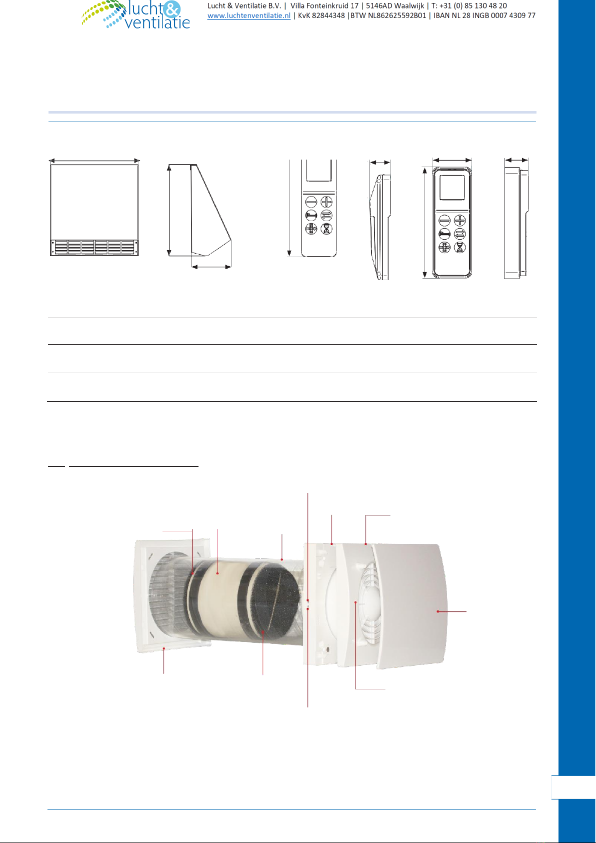
3.1
Features
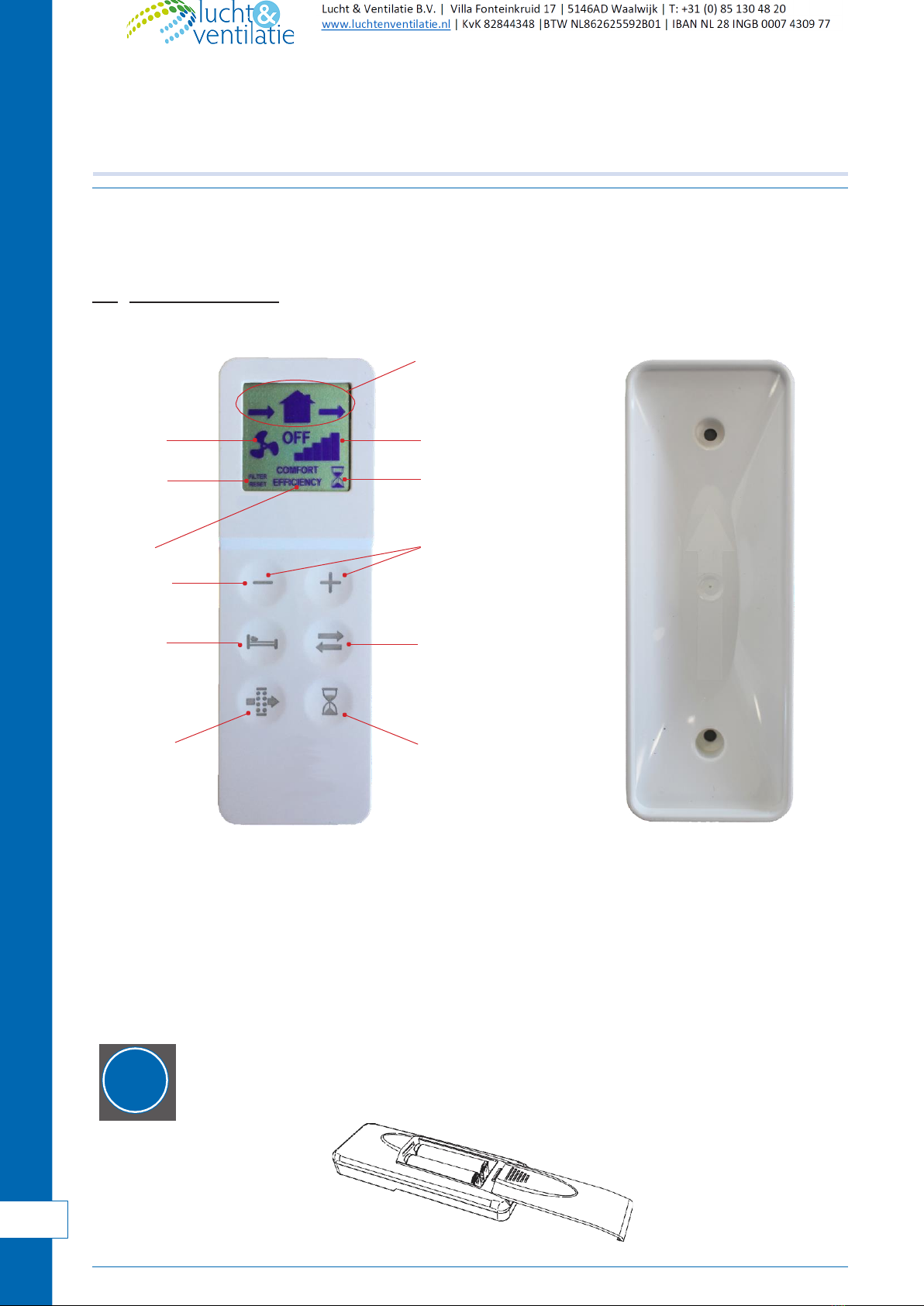
•
Design front cover (A) removable for cleaning without the use of tools.
•
Fan casing (B) and WAND support base (D) made of high quality, impact and UV-resistant ABS, colour
RAL9010.
•
Integrated multi-colour led (C ) to inform about the unit status.
•
Smart humidity control
•
Integral temperature sensor for the automatic management of the inversion time (comfort mode)
•
Automatic anti-frost protection to prevent frost formation on the heat exchange.
•
WAND support base (D) provided with a magnet “coupling/uncoupling” system which allows the
ventilation
unit to be removed from its base during maintenance.
•
Back-up touch button (E) at the side of the ventilation unit
•
Unique design winglet-type impeller, providing enhanced aerodynamic properties, low noise and increased
efficiency.
•
Efficient reversible EC motor with integral thermal protection, mounted on sealed for life high quality ball
bearings. Designed for continuous reversible running.