Luma 700 Series User manual

700 Series Bullet
500 Series Bullet
IP-Enabled HD Surveillance Camera
Installation
Manual
®
Important!
Ensure your NVR
has the latest
firmware!

2 3
Luma 500/700 Series Bullet IP Camera Luma 500/700 Series Bullet IP Camera
Additional Resources
If desired, you can add an SD card (up to 128 GB) to the camera. An SD card or a network drive is required if you
want to keep a log of the camera’s activities.
You can acquire a PDF of the web interface manual and other materials from the product page at SnapAV.com.
Safety Tips
}Handle this device with care.
}Do not strike or shake this device.
}Do not operate this device beyond its specified power source ratings.
}Protect the power cord from being stepped on or pinched, particularly where it connects to the device and
to the power outlet.
}Do not use this device near any heat sources such as radiators, heat registers, stoves, or other such heat-
generating equipment.
}The performance and lifespan of the SD card (if used) is affected by temperature. For best results, use this
device in temperatures ranging from -22–140 °F.
}Clean this device with a dry cloth. Do not use strong or abrasive detergents when cleaning the device,
especially the lens. If dirt is hard to remove, use a mild detergent and wipe gently.
}Make a note of the configuration settings and save them. This helps when changing the configuration,
when upgrading the device, or with recovery if unexpected failure or trouble occurs.
Read this page before you go to the job site!
For maximum control and convenience, connect your camera to the Internet via your NVR or through a local
network router.
Internet connectivity allows you to use OvrC, a powerful remote maintenance service. See OvrC.com for details.
In addition, Internet connectivity allows your client to use the Luma Surveillance mobile app to check on the
camera from anywhere.
For installation using this guide, you must be able to access this camera through a personal computer. If your
surveillance system is not on a network, you’ll have to use the NVR’s local interface for installation. See the NVR
user’s manual for details.
Required Equipment
}This camera and all box contents
}A network connection (and an NVR, if desired)
}Admin rights to a computer that can access the network
}Power source: either PoE or 12V DC
}Mobile phone with the Luma Surveillance mobile app (recommended) or CCTV tester
}Phillips screwdriver

4 5
Luma 500/700 Series Bullet IP Camera Luma 500/700 Series Bullet IP Camera
Overview
Before installing, familiarize yourself with the parts of your camera.
Installation
Before you start, ensure that the device is in good condition and all the assembly parts are included. Also ensure
that your recorder has the very latest firmware. Use OvrC to update the firmware, or consult your NVR manual.
}Ensure the mounting surface is strong enough to hold three times the weight of the camera plus the mount.
}If the mounting surface is cement, use the included wall anchors to install the camera. If mounting to a
wood surface, secure the camera using self-tapping wood screws (not included).
}If the product does not function properly, please contact technical support. Do not disassemble the camera
for repair or maintenance.
Box Contents
}Camera
}Self-adhesive mounting template
}4 x wall anchors (with screws)
}3mm hex wrench
}CC tester cable
}Weatherproofing kit for PoE cable
®
Important!
Before attaching this to
your Luma NVR, update
the recorder to the latest
firmware! If you don’t,
essential features of your
camera may not function.
Access panel
underneath
the camera
Sunshade
Adjustment
Screw
Sunshade
Level
Screw
Elbow
Screw Base
Screw
Reset Button
Access
Panel
Video
Port
SD Card
Slot

6 7
Luma 500/700 Series Bullet IP Camera Luma 500/700 Series Bullet IP Camera
Weatherproofing the PoE Cable
1. Before terminating the RJ45 cable , slide it through the lock nut , the thick rubber gasket , and the
weatherproof endcap as shown. Ensure the notched side of the rubber gasket faces the endcap .
2. Terminate the RJ45 cable with a network plug .
3. Place the O-ring onto the end of the camera’s network interface socket with the flat side toward the
camera. Push it past the locking teeth as far as it easily goes.
4. Connect the RJ45 plug to the camera’s network socket .
5. Align the teeth on the weatherproof endcap with the gaps on the camera’s network interface socket ,
then insert the socket into the endcap. Twist until they click into position (the O-ring gives you a little
flexibility while still weatherproofing the connection).
6. Slide the thick rubber gasket into the weatherproof endcap , and secure it by screwing the lock nut
tightly onto the endcap .
Prepare for Installation
1. Drill a cable hole and pilot holes for your screws in the mounting surface,
using the supplied template shown. The cable hole needs to be at least
1 inch wide.
2. CAUTION! Before terminating your RJ45 for an outdoor install, you
must weatherproof it! See the next page for how to weatherproof
your cable.
3. Attach power to the camera.
}If using PoE, attach the RJ45 cable to the connector.
}If using 12V DC for power, locate the red and black wire bundle
(on the 700, there are two sets of wires: one has red and black only,
the other is a bundle of eight). Attach the hot line to the red wire, and
the ground to the black wire.
4. For the 700 only: Connect the leads in the eight-wire bundle as shown for additional features. Secure all
other wires so they don’t cause a short circuit.
}Blue Alarm in hot
}Green Alarm in ground
}Black Alarm out hot
}White Alarm out ground
}Orange Audio in hot
}Gray Audio in ground
}Purple Audio out hot
}Red Audio out ground

8 9
Luma 500/700 Series Bullet IP Camera Luma 500/700 Series Bullet IP Camera
Install the Camera with No Recorder
1. Route the cables through the cable hole.
2. Attach the base of the camera to the mounting surface and secure it with screws.
3. Plug the camera into your network switch or router.
4. Attach either a PoE cable or a power supply.
5. Check that the camera is powered up.
6. Continue setup using the steps on the following pages using the camera’s web interface.
Install the Camera with an NVR
1. Route the cables through the cable hole.
2. Attach the base of the camera to the mounting surface and secure it with screws.
3. Ensure your NVR has the latest firmware. If it does not, you may experience troubles locating the camera,
and certain functions may not work.
4. Plug your camera into your recorder. The NVR autodetects your camera and assigns it an IP address.
5. Check that the camera is powered up.
6. Complete the installation using the instructions given with your NVR’s guide. You do not need to continue
using this manual. Wherever possible, we recommend changing settings using your NVR.
Optional Extra Setup
This camera has a few features that are not available on your NVR.
}It has advanced detection features: line crossing and area intrusion. After completing installation, see the
camera’s web interface manual to set these up.
}The 700 (only) has a motorized varifocal lens. See page 15 for details. You can adjust the lens from your
camera’s live view screen or from the NVR’s live view screen.

10 11
Luma 500/700 Series Bullet IP Camera Luma 500/700 Series Bullet IP Camera
Edit the Network Settings
If you need to change the network settings at a later date, consult the web interface manual.
Set the IP Address
At the top of the right column of the Luma Utility, make a note of the IP address;
you’ll need it in the next step.
Deselect the Enable DHCP box to make the IP address static.
Change the Server and HTTP Ports
The HTTP port defaults to 80. This port enables you to access your camera through
a web browser.
The server port defaults to 8000. This port enables the Luma Surveillance mobile
app to access your system.
For security reasons, we suggest you change your ports and make a note of the new port numbers for your records.
Consult your server or router manual for common and reserved port numbers to avoid.
To confirm changes, enter the password admin and then click Save.
Discover the Camera
If you plugged your camera into an NVR, do not continue using this guide! Complete the setup using the manual
provided with your NVR.
If you are not using an NVR is your installation, continue setup using the following instructions.
Download and Install the Luma Utility
Visit any NVR’s product page at SnapAV.com and download the Luma Utility installer. The
utility locates your camera and sets up communications.
Once it has downloaded, double-click on the Luma Utility icon to run the installer. You can
click through and accept the defaults.
Run the Luma Utility
Double-click the Luma Utility icon to run the program.
It searches the local network for all Luma Surveillance devices. If your camera does not appear,
ensure that the network connections are secure and that the camera is powered up, then click
the button.
Click on the entry for your camera to view its details. Double-clicking on the camera opens its
web interface. Note that Chrome is not a supported browser for the web interface.

12 13
Luma 500/700 Series Bullet IP Camera Luma 500/700 Series Bullet IP Camera
Check the Camera
After logging in, your screen shows the live page, which should look similar to the illustration below. If it does not
appear, check the connection to your network, and ensure that the camera is powered up.
Click the Settings Menu icon to access the web interface tools and finish setup.
Start the Web Interface
Get the Luma Plug-In
Open your browser, type the IP address of the camera into the address bar, and hit Return.
Below the login window, you may see the words, “Please click here to download and install the plug-in. Close
the browser when installing the plug-in.” If so, download the plug-in and close all instances of your browser,
including any running in the background.
Install the LumaWebComponents plug-in.
Restart your browser and return to your camera’s login window.
Enter admin for both the user name and password.
You might get a pop-up message that asks whether you want to run the Luma Web Components
plug-in. You must allow the plug-in to access your system over the web.
Be sure to save your camera’s web page as a favorite in your browser.
Note that Google Chrome is not a supported browser.
Settings
Menu
Icon
PTZ
Icon

14 15
Luma 500/700 Series Bullet IP Camera Luma 500/700 Series Bullet IP Camera
Adjust the Zoom and Focus (700 only)
The 700 series has a motorized varifocal lens.
To adjust the focus, return to the live screen (see page 13) and click the PTZ icon . This
opens up the PTZ menu on your screen.
In the PTZ menu, click on the buttons circled.
}The Zoom– button on the top left widens the angle of vision, providing a more
panoramic view.
}The Zoom+ button on the top right lowers the angle of vision, providing a tighter
view.
}The Focus– button on the bottom left focuses on near objects.
}The Focus+ button on the bottom right focuses on distant ones.
Adjust the Camera
1. This camera has an elbow joint flanked by two rotational joints for perfect pan and tilt control. Loosen the
three hex screws in the camera. Check the camera’s aim using either the camera’s web-based UI, the Luma
Surveillance app, or a CC tester.
2. Adjust the angle of the elbow as desired, and tighten the elbow hex screw, A. Rotate the camera so that
it faces the proper direction, and tighten the base screw, B. Finally, spin the camera casing so that the
picture is level, and tighten the level hex screw, C.
3. Adjust the sunshade. Use a quarter to loosen the sunshade screw (do not remove it). Slide the shade to the
desired position, and tighten the screw when finished. We recommend that you do not remove the shade,
even for indoor installations.
Level
Screw
C
Elbow
Screw
A
Base
Screw
B

16 17
Luma 500/700 Series Bullet IP Camera Luma 500/700 Series Bullet IP Camera
Set Up Port Forwarding
Port forwarding is typically found under the Applications & Gaming section of your router. Refer to your router’s
user manual for full details.
To complete port forwarding, you will need:
}the IP address of the camera, and
}the server and HTTP port.
You set these values on page 11.
Once you’ve finished, pointing your browser to your device’s URL (example: MyHome.WirepathDDNS.com) gets
you to the login page of your camera, no matter where you are. If you changed your HTTP port from the default
location (80), add a colon and the new port number to the URL (e.g., MyHome.WirepathDDNS:8042).
Set Up Dynamic DNS
DDNS allows you to connect to your surveillance system from anywhere, via the Internet, using a web address
that’s easy to remember.
Click on Basic Network Settings > DDNS.
Click the box labeled Enable DDNS, then choose a type from the DDNS Type drop-down
menu. We recommend WirepathDDNS. Next, choose a server address. We recommend
ns2.wirepathdns.com.
Enter your desired domain in the Domain box. This creates a personalized server address,
which is shown under Device URL.
If someone has already registered your desired domain, the system adds a unique ID
(typically two to four digits) to your domain.
If you do not like these digits, try another
domain or server address.
Example: If you choose the domain myhome
(as shown), your system’s URL would be
myhome.WirepathDDNS.com. If someone
already had claimed the myhome URL, then
your system’s URL would be something like
myhome13.WirepathDDNS.com.
Click Save to finalize the settings here.

18 19
Luma 500/700 Series Bullet IP Camera Luma 500/700 Series Bullet IP Camera
Calibrate the Camera’s Clock
Click on System Settings > Time Settings.
Synchronize the Time
At the top, choose your time zone. North American time zones range from GMT-10:00
(Hawaii) to GMT-03:30 (Newfoundland).
By default, the system uses network time protocol (NTP) to synchronize your system to
Coordinated Universal Time. We strongly recommend using NTP to keep your system
well calibrated.
If you want to use manual time sync, or if your system is isolated from the Internet, see
the camera web interface manual (available online).
Disable DST if Necessary
If you are in a location that does not observe daylight saving time, click the Enable DST
checkbox to deselect it.
Click Save to confirm changes.
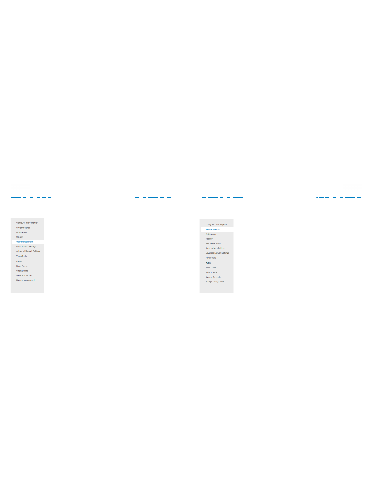
Create Users and Set Passwords
Click on User Management.
Change the Admin Password
Click on the admin account, then click Modify.
Passwords cannot be longer than 16 characters. If you are using an NVR, to ensure
compatibility with the NVR’s local interface, passwords can only contain numbers,
letters, spaces, and the following special characters: . , : - /
Use a password that is long and easy to remember. A password like parisinthespring is
much more secure and easier to remember than a password like D3x^7b.
Add Additional Users
Click the Add button. Enter the new account’s user name and password. Account names
can be up to 32 characters long. If you are using an NVR, to ensure compatibility with
the NVR’s local interface, user names should contain numbers and letters only.
We recommend that you add accounts by individual users’ names, so that you always
know which user is involved with any activity.
Choose the account’s level. There are two levels for users: operator and user. The only
difference is the default permissions they are given. You can customize permissions for
each account individually. See the camera web interface manual (available online on
your camera’s product page) for more details.

20
Luma 500/700 Series Bullet IP Camera
Support
Need Help? Contact Tech Support!
If you need further clarification, please email support@SnapAV.com. For more information, instructional videos,
support documentation, or ideas, visit our website and view your item’s product page.
3-Year Limited Warranty
This Luma Surveillance™ product has a 3-Year Limited Warranty. This warranty includes parts and labor repairs
on all components found to be defective in material or workmanship under normal conditions of use. This
warranty shall not apply to products that have been abused, modified or disassembled. Products to be repaired
under this warranty must be returned to a designated service center with an assigned return authorization (RA)
number. Contact technical support for an RA number.
Copyright ©2016 by SnapAV. All rights reserved. SnapAV, Luma Surveillance, and all related marks and images
are trademarks or registered trademarks of SnapAV.
Version 160712-1359
Other manuals for 700 Series
1
This manual suits for next models
1
Table of contents