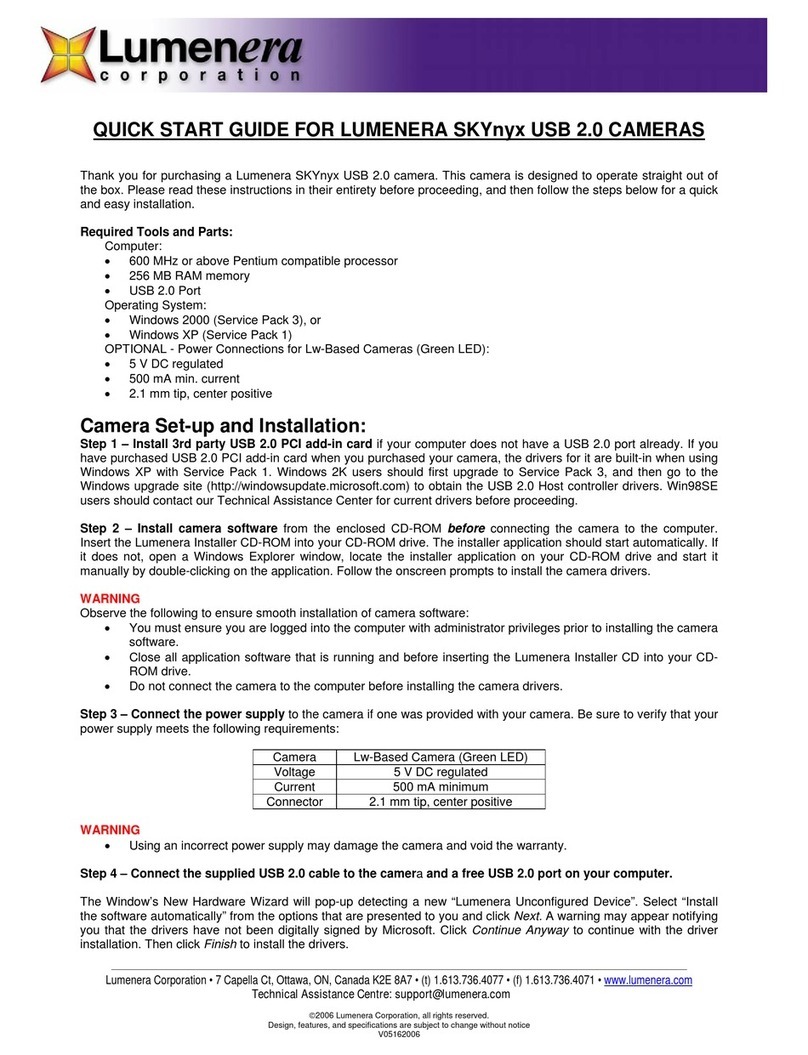
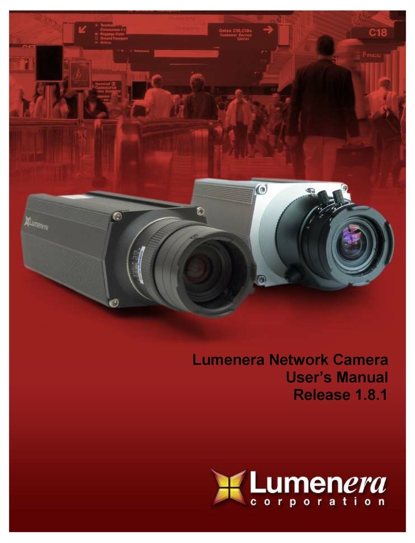
Lumenera Le045 User manual

LUMENERA QUICK START GUIDE WWW.LUMENERA.COM
7 CAPELLA COURT, OTTAWA, ON, CANADA K2E 8A7 | LEIPZIG, GERMANY | ATLANTA, GEORGIA, USA | TEL (613) 736-4077 | FAX (613) 736-4071 | WWW.LUMENERA.COM | [email protected]
© 2011 Lumenera Corporation. All rights reserved.
Design, features, and specifications are subject to change without notice
0726011
Camera Model Power Supply Specications
Recommended Lumenera Power Supply for
Non-PoE Applications
Standard Format:
e.g. Le075CP, Le165CE, Le165CP, Le175CA, Le275CP, Le375CP, Le575CP
PoE or
12 to 48 V DC / 2 A / 24 W max. La21224N
(formerly Lu8501)
Le045 & Intelligent Series:
e.g. Le045CB, Li045CB, Li165CB PoE or
24 to 48 V DC / 1 A / 24 W max. La22424N
(formerly Lu8401)
Li175CB Intelligent Camera:
Li175CB (only) PoE or
24 V AC / DC / 1 A / 24 W max. La22424N
(formerly Lu8401)
PART II: CAMERA REQUIREMENTS
QUICK START GUIDE
Network Camera
The exact power and lens requirements vary by camera type. The camera model (e.g. “LE165CE-DN”) can be located on the
camera’s white barcode label.
Thank you for purchasing a Lumenera network camera. Follow this guide for quick and easy installation. Please read the
instructions in their entirety before proceeding.
Tools required when installing with an external power
supply:
• Small screwdriver (1.8 mm) flat head
• 18 to 28 AWG wire
• Black 10-terminal locking connector (included)
(Replacement part no. Le903)
1. TOOLS AND PARTS
3. POWER
CS or C-mount Lens Optical Format Chart
Camera Model Optical Format
Le045 / Li045
1/3”
Le075 1/3”
Le165 / Li165 2/3”
Le175CA / Li175CB 1/3”
Le175MP / Li175MB 1/2”
Le275 1/2”
Le375 1/2”
Le575 1/2.5”
Power over Ethernet
PoE (IEEE 802.3af) switch or mid-span injector replace external power.
Network Connection
Cat5e twisted pair cable with RJ45 connectors, 100BASE-TX Ethernet connection.
2. LENS
PART I: CAMERA MODEL
Standard Format (White) Le045 & Intelligent Series (Black)
Refer to the power supply chart below to avoid camera damage. Lumenera includes a set of international wall plugs with
all power supplies.

LUMENERA QUICK START GUIDE WWW.LUMENERA.COM
7 CAPELLA COURT, OTTAWA, ON, CANADA K2E 8A7 | LEIPZIG, GERMANY | ATLANTA, GEORGIA, USA | TEL (613) 736-4077 | FAX (613) 736-4071 | WWW.LUMENERA.COM | [email protected]
© 2011 Lumenera Corporation. All rights reserved.
Design, features, and specifications are subject to change without notice
07262011
PART III: CAMERA POWER-UP AND INSTALLATION
Connect Ethernet Cable to Camera
Using a standard Cat5e cable, connect your network to the camera’s RJ45 “ETHERNET” port. If connecting the
camera directly to a PC, use a crossover cable. For PoE-compatible camera models, a PoE switch or mid-span power
injector can be used to provide power to the camera.
Apply Power
Plug the power supply into a power source. If using PoE, turn on the PoE switch or mid-span power injector. For
most camera models, the orange light on the left of the RJ45 socket will be active during start-up. A valid network
connection is indicated by activity on the green link light.
OPTIONAL - Connect to Camera Using a Web Browser
Type the link-local IP address, located on the camera’s white barcode label (e.g. 169.254.93.123), into the address
bar of a web browser. This will connect you to the in-camera web server and allow you to view images and change
camera settings. For complete details contact Technical Assistance at [email protected] to obtain a copy of the
User’s Manual.
OPTIONAL - Connect Analog Video/Audio Cables
Some cameras provide BNC connectors for NTSC analog video output or audio input/output. For complete details
Warranty and Liability: www.lumenera.com/support/warranty-policy.php
Network Camera Application Notes: www.lumenera.com/support/guides-appnotes/surveillance-appnotes.php
IP Discovery and Connectivity Application Note: www.lumenera.com/support/pdf/LA-2113-IPDiscoveryAndConnectivity.pdf
Apple’s Bonjour Print Services for Windows: www.apple.com/bonjour/
PART IV: Additional Resources
Attach Power Supply to Camera (If using PoE skip to Step 4)
Disable the power at the source then carefully attach the power supply to the
camera by connecting the power wires to the black 10-terminal connector. To
do so, unlock the round opening of the power terminal by inserting a small flat-
head screwdriver into the square hole next to the terminal. Place the wires in the
terminal then release the screwdriver to lock them into place.
Distinct back plate configurations are used on each of the Intelligent Series and
Standard Format camera models. Each back plate is clearly etched with the pin-
outs and appropriate labels.
Attach the Lens
The camera is designed to accept a CS-mount. A C-mount lens can be used with a 5 mm spacer (optional accessory
available from Lumenera). To install the lens remove the black plastic cap from the camera by turning anti-clockwise.
To mount the lens, gently turn the lens in a clockwise direction until it stops against the camera body, being careful not
to overtighten. For a DC iris lens, connect the control cable to the 4-pin connector socket at the rear of the camera.
Verify External Power Supply Specications
Prior to installing the power supply you must ensure the external power source meets the requirements listed on the
previous page (Part II, no 3). Observe the following to prevent damage and protect the camera warranty:
• Ensure to connect the correct polarity (the positive (+) lead of the power supply is indicated by white
dashes on black insulation)
• Voltageappliedtothepowerterminalsshouldnotexceedthemaximumrating
• User-suppliedwiringtotheunitmustbeincompliancewithapplicablecodesforelectricalequipment
• WhereanACpowersupplyisused,donotgroundeitherterminalorcamerachassis
• Avoidhot-pluggingpowerconnectorsintotherearofthecamera
!
7
STEP
6
STEP
5
STEP
4
STEP
2
STEP
3
STEP
1
STEP
This manual suits for next models
11
Table of contents
Other Lumenera Security Camera manuals


