LUMLUX Lightspeed 315W 208-277V User manual

315W 208-277V DIMMABLE SYSTEM

www.HydrotekHydroponics.com
Distributed by
INPUT CHARACTERISTICS
Parameters
Conditions
Min
Type
Max
Units
Mains Voltage
Operational Voltage
187
208-277
305
V
Safe Voltage
177
208-277
319
Mains Frequency
fmains
Operational Frequency
48
50/60
63
Hz
Safe Frequency
45
50/60
66
Mains Power
Pmains
W
P=100%
331 342 353
P=90%
297 308 319
P=80%
263 274 285
P=70%
230 241 252
P=60%
196 208 219
P=50%
163 174 185
Mains Current
Imains
Vmains =277V
A
Vmains =208V
Power Factor
P=100%
P=100%
0.96
0.97
--
--
THD
--
--
15%
--
Inrush Current
Vmains =277V
Ta=25°C,cold start
--
--
30
A
Pulse Duration
--
--
0.8
ms
1.2 1.3 1.4
1.6 1.7 1.8
OUTPUT CHARACTERISTICS
Parameters
Conditions
Min
Type
Max
Units
Lamp Frequency
f
lamp
110
120 130
Hz
Efficiency(%)
91 92
--
--
Lamp Power
P
lamp
W
P=100%
P=100%
P=100%
306 315 324
P=90%
274 284 293
P=80%
243 252 261
P=70%
211 221 230
P=60%
180 189 198
P=50%
148 158 167
Lamp Voltage
315 CMH
90
100
115
V
Ignition Voltage
C
load
<100pF
3000
4000
5000
V
Ignition Interval
--
0.5-0.5-0.5-5-5-5-5-10
Min
Note: The certified current of this product is: 1.2A

RECOMMENDED MATCHING LAMP TYPE
315W CMH
Distributed by
CANDELA DISTRIBUTION
This product must be installed in accordance with applicable national and local electrical and construction
codes by a person familiar with the construction and operation of the product and the hazards involved.
www.HydrotekHydroponics.com
Vertical plane through horizontal angles (0-180) : 135DEG

Distributed by
www.HydrotekHydroponics.com
REMOTE DIMMING WITH OPTIONAL DIGITAL CONTROLLER
REMOTE CONTROL FUNCTION
All output specifications are reported as a percentage of the full ballast rating
EXP: 80% of 315W ballast = 252W.
Output Mapping Equation (W): (Dimming ratio)*ballast rating=Output.
Note:1.Dimming accuracy is 3% (as per the output power of Vmains =208V).
2.When the dimming ratio is 0%, the ballast will be off; user can set
the parameters show in the 50%-100%.
It can control remotely the ballast's on/off/dimming rate.
Group control mode: itcan control the state of a set of products.
Single lamp control mode:
it can control the state of a single product.
Sun rise and set: when the SR/SS set time is 0 min, the ballast will power
on/off as its own speed, actually, it’s exactly same as Power on/off.
If no controller, the ballast can work with full power. If the controller is connected,
it will work at the controller's power.
•
•
•
•
•
Dim signal
Output Power ( W)

LED Flashes Status Solution
- For indoor use only.
- Install the system in a cool, dry, well-ventilated location.
- Ensure the power source meets the specifications of the unit.
- The power cord and any extensions used must match the voltage supplied to the system and meet standard
electrical safety requirements.
- Modifying or opening the system will void the warranty.
- When resetting the ballast, a 15 minutes cool down period is required between lamp ignitions.
- Wear safety glasses and gloves when installing lamp.
The Lightspeed 315W dimmable system is equipped with an LED status indicator and an internal troubleshooting system.
- With no connected power supply, the ballast LED will be off.
- With power supply connected, the ballast LED will illuminate.
Note: When connected to the Lightspeed Digital Controller, the ballast LED status indicator will be off and instead the controller LED
will be lit and flashing.
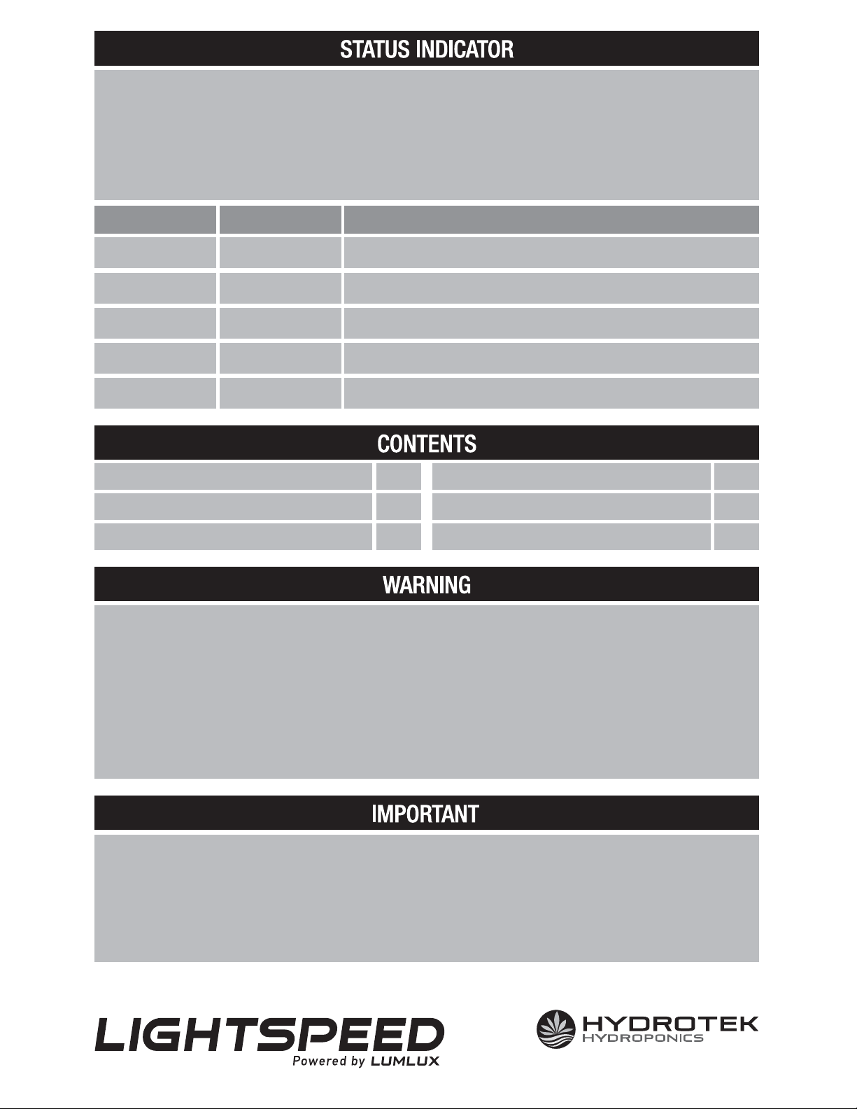
- If a system error occurs, the LED status indicator will flash abnormally. Refer to this chart to determine the signaled error:
- If the lamp fails to ignite:
• Verify all electrical connections.
•
Check for errors via the LED status indicator (See instructions under “LED Status Indicator”) and make the necessary correction.
- Should the fixture continue to fail, contact the point of sale for warranty and repair instructions.
- Prior authorization from Technical Support is required before opening the ballast and accessing internal components.
Any unapproved attempt to open and/or repair the ballast will void the warranty.
1
1
2
3
4
5
Ballast locked
Output error
Low input voltage
High temperature
High input voltage
1
1
1
1
1
315W CMH Ballast Connecting Cable With Wieland Plug
Hanging hooks set
System-to-system signal cable
Reflector
Instruction Manual
The ballast failed to ignite the lamp after five tries. Verify and reconnect the power source.
The lamp stopped for unknown reason. Check whether the lamp is correctly mounted.
The input voltage is too low. Ensure the input voltage matches the power cord and ballast
specifications.
The input voltage is too high. Ensure the input voltage matches the power cord and ballast
specifications.
The ballast is overheated, to keep the environment temperature lower.
www.HydrotekHydroponics.com
Distributed by

Avoid handling the lamp with bare hands, as dirt and oils will affect its efficiency and lifespan.
1) Disconnect the light fixture from its power source.
2) Screw the Lamp in the socket.
3) Gently wipe the lamp clean with a soft, dry, lint-free cloth.
1. Screw the provided hooks into their receptacles at the top of the reflector arm and ballast.
2. Hang the system from an adequate support using chain, ratchet hangers, or other suitable
cables. Allow space around all sides of the unit for sufficient airflow.
3. Attach the female end of the power cord to the male input receptacle on the ballast.
4. (Optional) Connect the unit to the advanced Digital Lighting Controller via a connecting cable,
following the controller instructions. When linking multiple units, use the included
connecting cable to connect ballasts.
5. Plug the male end of the power cord into a properly grounded outlet to power on the system.
B
466 mm
271 mm
227 mm 241 mm
160 mm
A
Manufactured by LUMLUX
Distributed by Hydrotek Hydroponics
Mirabel, QC, Canada J7J 2K4
www.HydrotekHydroponics.com
Table of contents
Popular Outdoor Light manuals by other brands

HEPER
HEPER MINIMO 4x90 Installation & maintenance instructions

Festive Lights
Festive Lights SL165 manual

Quoizel
Quoizel WWD8408IB installation guide

EINHELL
EINHELL RT-CL 12 Li Original operating instructions

Urban Electric
Urban Electric MARKHAM Assembly and mounting instructions

Leader Light
Leader Light LL STREET PS60 user manual