OPERAT¡ON
PLAYBACK FROM RECORD DISC
ICONNECTIONS
Generally a record player consists of a turntable ensuring
constant rotation of the record disc a pick-up (cartridge)
whose stylus (needle) traces the sound groove of the disc
converting the physical signal of the record sound into the
electric signal, and the arm which holds this cartridge. The
player has 2 cords with pin plug at its end for both right
and left channels. Connect the pin connectors to the input
terminals of this receiver IPHONO-1(37) or PHONO-2(37)].
A probable earth lead of player may be connected to the
GND terminal(4O) of this receiver. A mains cord of the
player to drive its motor may be connected to lhe con-
venient extra mains outlet(28) (E and U type only).
This receiver is provided with 2 input terminals (PHONO-1
and PHONO-2) to be selected by the input selector
switch( 1 ), which is useful for comparison test of 2 pick-
ups or using 2 record players. For use of 1 player either of
2 input terminals can be selected.
ISIGNAL PATHS
Put the disc on the turntable, switch on the phono motor,
and set the stylus on the groove of disc. Then recorded
signals begin to be fed to the receiver. First, signals fed to
the receiver through PHONO terminals are brought to the
equalizer section, where recorded signals are equalized and
restored to the original frequency curve. lncidentally this
equalizer curve has been standardized to the RIAA curve.
The equalized signals are then fed to the input selector
swilch (function switch). lf th¡s switch ¡s not set at the
correct position of PHONO, the signals are blocked here
and no more advance is possible. Then the signals are
divided into 2 channels, one line to the recording output
terminal, and the other to the tape monitor switch, Then
the tape reprint switch which is effective on both channels.
lf the monitor sw¡tch(11) is set at the "source" position
the signals are sent to the mode selector switch, and volume
control, but if at the "deck-1 " or "deck-2" position the
tape monitor terminals start to f unction and lhe signals are
stopped at this point. Except when the tape playback is
made by tape monitor terminals, the monitor switch must
be kept at the "source" positon. But when the input
signals are fed to PHONO or AUX terminals recording
output is always obtainable regardless of the positíon of the
monitor switch. Then the signals are sent to lhe volume
control through the mode selector, f ilters, and loudness
control. lf the volume knob is turned to the extreme end
of counter-clockwise direction, the signals cannot proceed
ahead. lt is necessary to set this control at the optimum
volume.
Such controls as linear equalizer, low-cut filter, high-cut
filter, loudness, and tone controls are for flexible and
diversified adjustment of playback sound and do not block
the signals completely. Then the signals reach the speaker
switches amplif ied by the main amplifier. Sound playback
from speaker systems is thus realized if the speaker switch
corresponding to the speaker terminals to which the
speakers are connected is set at the correct position. The
above is the feeding path of PHONO signals starting from
input terminals to the speaker systems. Difficult as it may
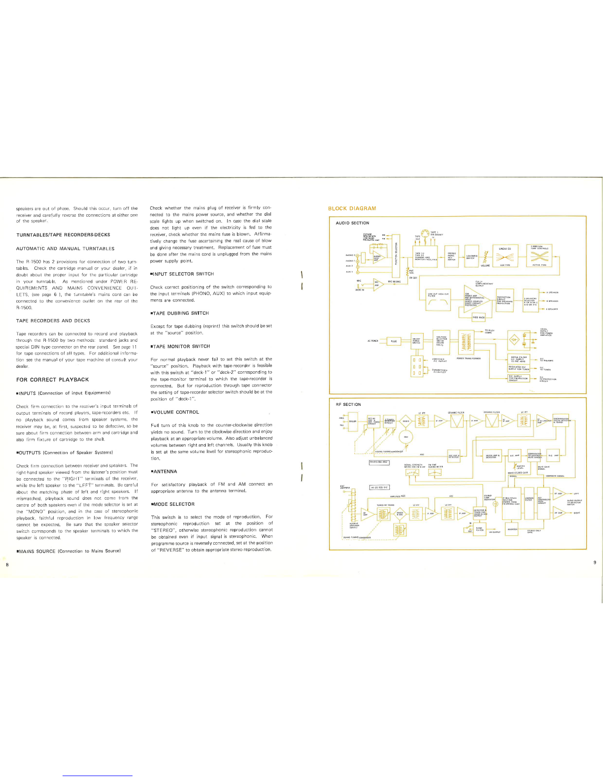
sound you can easily understand it from the attached block
diagram. For your pleasant command of this receiver we
recommend you to bear the block diagram in your mind.
TPLAYBACK PERFORMANCE
Now put a disc on the turntable for playback performance.
As the volume control is turned clockwise from the cut
position, playback sound comes out from speakers. As
explained in the paragraph of Sìgnal Paths the sound
playback is possible regardless of the posìtion of [Vode
Selector etc. as far as these essentìal controls are set at the
correct position such as Input Selector Switch(1),
Tape Dubbing Switch(.1 0), lVonitor Switch(11), Speaker
Selector Swjtch(23) and Volume Control('l 2). Now all
preparations have been completed. Check if the volume
levels on both right and left speakers are identical. lf
deviated adjust it by the Volurre Control. For stereophonic
playback see to ¡t that the lVode Selector Swìtch ìs kept at
the "stereo" position, otherwise correct stereophonic
playback is not feasible.
PLAYBACK OF AM/FM BROADCASTING PROGRAM
Selection of the input selector( 1 ) at the AM or FM
position ensures playback of AIV or FM broadcasting
programme, lf you want you can connect other tuner
(AM, FM, LW or SW etc.) to one of the AUX terminals of
this receiver. ln this case the selector must be set at the
corresponding position. As shown in the block diagram
the input signals from the tuner sect¡on on AUX terminals
are directly fed to the lnput Selector Switch. Afterwards
the signals trace the same blocks as explained in the para-
graph of Playback from Record Disc and are reproduced
from the speaker systems. Both for FM stereophonic and
monaural broadcasting the lVlode Selector Switch can be set
at the position of "FfVl", for such accommodation to
the ìnput source can be made in the tunersect¡on. In case
weak FM stereo is received and you feel ìt noisy, set the
l\4ode Selector SwiÌch( 9 ) at the "mono" position for
better reproduction. ln case of AM/LW programme from
other tuner there is possible trouble of modulation hum,
which can be eliminated bV varyinq the distance and angle
of these components.
OTHER TUNER
OTHER PLAYBACK
The signals of flat frequency response from such sources as
TV receivers do not need an equalizer stage, and for play-
back of such audio equipments any of these AUX termirrals
can be used, Connection arrd operation is same with that
of AM/FN/I broadcasting programme.
PLAYBACK FROM TAPE
TPLAYBACK FROM TAPE MONITOR TERMINALS
Almost all of tape-recorders, and tape-decks currently
markeled integrate audio pre-amplifiers in their circuit.
Also there ls a tape-player exclusively for playback' Con-
nect the output terminal (LINE OUT) to the Tape I\4onitor
Termìnals(39). Then set the Monitor Switch(11) at
the corresponding position and the playback from tape
is realized lf 2 tape-recorders are connected to the
Terminals(39), selection between 2 tape-recorders is
possible by the Monitor Switch(11). This amplif ier sectiot'r
can be devided into 2 sections - one before the Recording
Output Terminals(R EC. OUT) and the other after the
Tape lVonìtor Switch, and 3-head tape-recorder makes it
feasible to make recording with the former section and
simultaneously to make playback with the latter section.
Note lhat normal function cannot be expected if 2 sets of
tape-recorder for playback are connected to the terminals
of TAPE IVIONITOR-1 and Tape Connector(32) at the
same time, since these 2 are coupled in the inside circuit
and effect each other. Therefore if Tape Monitor Terminals
and Tape Connector are used the tape;recorders should be
connected to the terminals of TAPE MONITOR-2 and
the Tape Conrrector.
IPLAYBACK FROM AUX TERMINALS
recorder or tape-deck is connected to the AUX terminals of
this receiver by use of pin-jack lead and the lnput Selector
Switch is set aÌ the corresponding position to the AUX
Terminals. All operations ìn this case are same with those
for the Playback of Tuner. Note that when tape playback
is made thror.rgh AUX terminals, the line input or AUX
input terminals of the tape-recorder should not be con-
nected, lf connected to the Recording Output Terminals
(REC. OUT) of the receiver there wìll be possible oscilla-
tion by feed-back of signals.
IPLAYBACK FROM TAPE CONNECTOR
This connector is of DIN norm, and very convenient for
simple connection by a single patch cord between the
tape-recorder and recordit.rg/playback connectors of this
receiver" A DIN cord should be connected between DIN
connector of the tape-recorder and Tape Connector of this
receiver. Playback from Tape Connector is possible if the
Monitor Switch is set at the "deck-1" positlon.
RECORDING ON TAPE
In case of playback of various programme sources through
ìnput terminals of this amplifier, the same signals to these
reproduced ln speakers are available at the Recording
Outpu.t Terminals(38) and Tape ConnecÌor(32) if the
Tape Dubbing Switch is set at the "source" position.
By connection of these term¡nals to the ¡nput terminals
(AUX or LINE-lN) of the tape recorder you can enjoy
simultaneous recording and playback. These recording
signals are taken out before the Tape Monitor Switch and
there is no inf luence of such controls as Volume Controls,
Tone Controls and Fìlters etc.
TAPE DUBBING (Reprinting)
So called tape dubbing - tape-to tape reprinting is possible
wirh rhe Tape Dubbing Switch(10) Tape Dubbing is pos-
sible when the switch is set at the "up" (1 ro 2l or "down"
(2 ro 1) posìtion. At the "('1 to 2)" position connect
the LINE-OUT terminals of the tape-recorder with recorded
tape to the TAPE fVIONITOR-1(39) while the LINE-lN
(AUX) terminals of the second tape-recorder to the "REC.
OUf -2" (38), the tape dubbing is possible from the 1st .to
2nd tape-recorder: vise versa aI The "2 to 1" position'
Similarly tape dubbing ls possible between the TAPE
N/IONITOF-2 and rhe tape connector. ln the dubbing
process if the LIN E-l N terminals of the 1st tape-recorder is
connected to the "REC. OUT-I "(38) and the LINE OUT
of the 2nd tape-recorder to the "TAPE MONITOR-2"(39)
simple operation of the Monitor Switch(11) between
"deck-1 " and "deck-2" allows comparison between lhe
oo o
!J
+ .¡¡¡gkñ.
¿^
;O O;O-C-,
-coo-o.
10
Playback of tape is possible if the l¡ne output of tape
11