R-
341
|
Contents
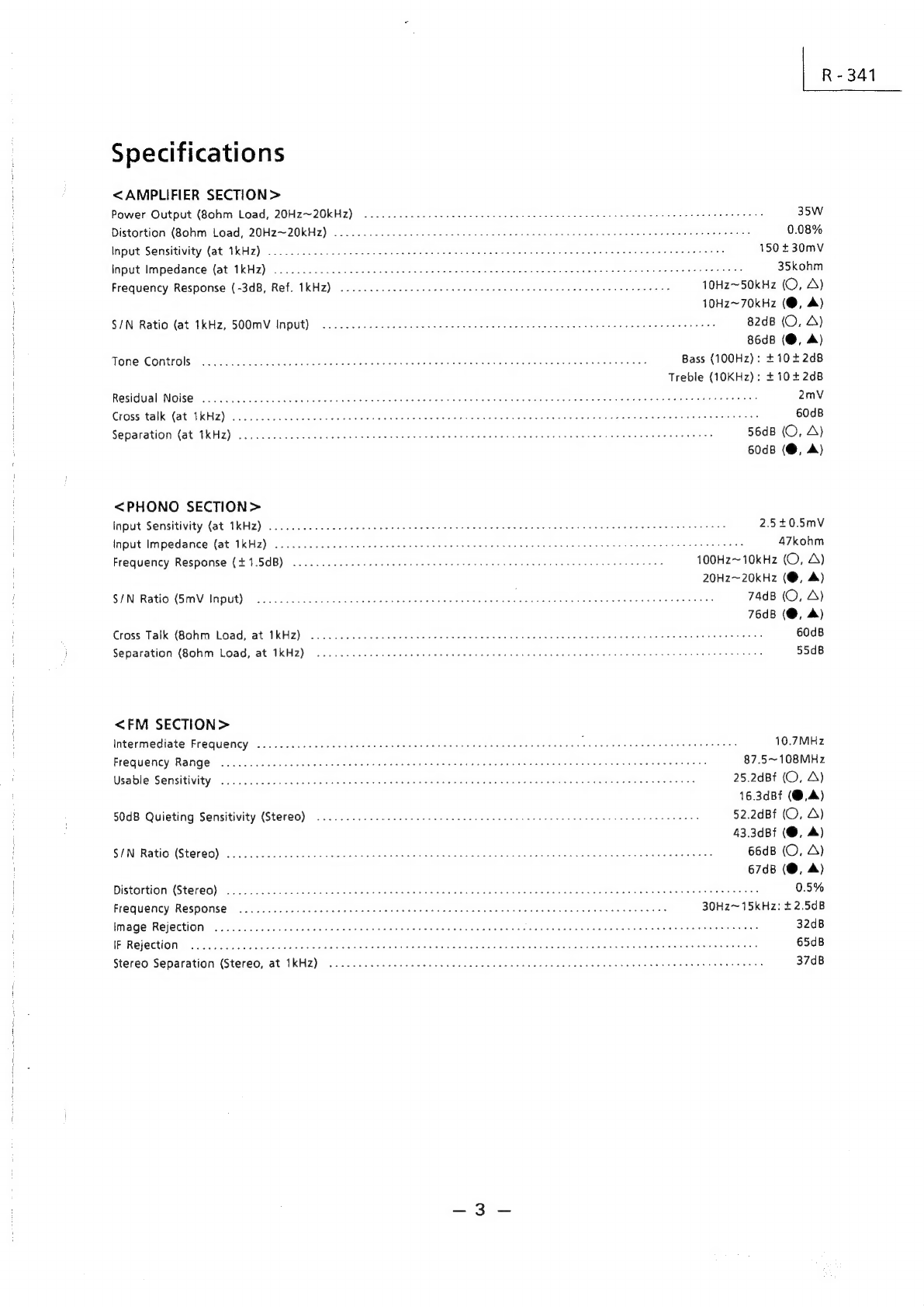
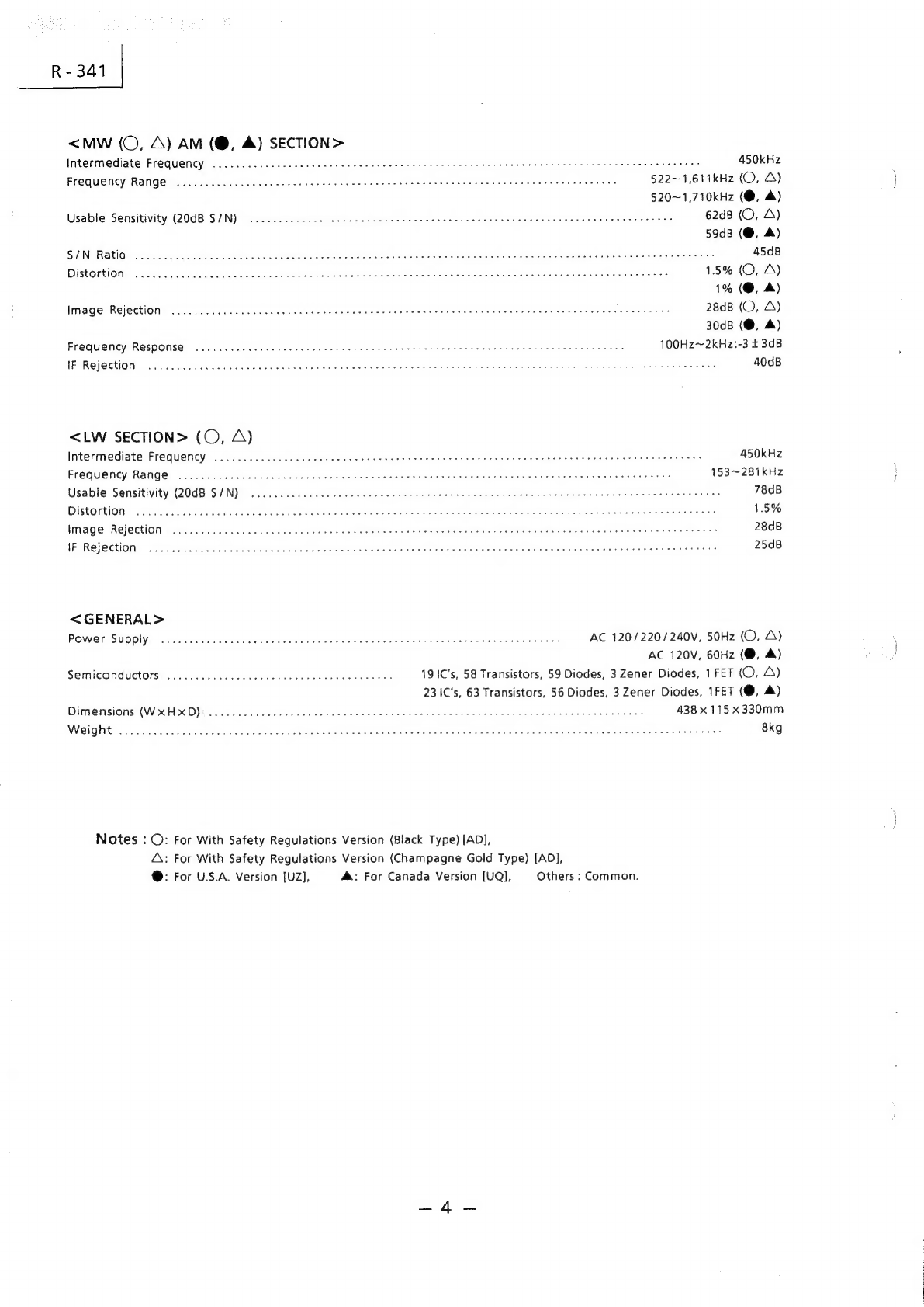
Specifications
.o.cccccccccsesessseseneeeeeseceececeessssesensescseseesesescaseseacseeceeenssseseeseseesaevecesseesaeeensecsicaessnenscssseeaeecanseseneneeeneeeneges
3to4
Connection
Guidelines
oc.
ccccccccccccsccsceseceeeceeeeceeeeeceeseeeeeseeeaesseesesessnsesneesesessseaccssetsesseesenseeneessesesneesieciensessaseeaereesay
5
to6
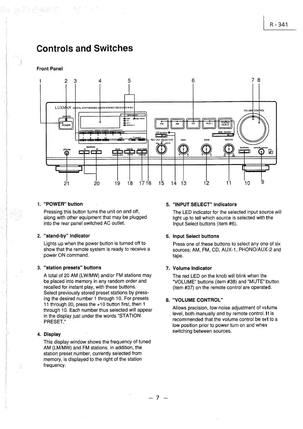
Controls
and
SWItChes
.......ccccccescccssecsccsessecscesceseecesseeseesecaecssesecsecsecersaseessecsscsussecsecsessesaessessesesseserseneeesseessesenaseneneesaeneees
7
to
12
Jacks
and’
TermimalS:....civicecechesidessileles.ccacsassdeesscastevescsciensenssehesaccanessgeunsdensvetestuneddndesveussnabedsssevesateadetstnatagnedeededsaoee
Giows
13
to
15
Operation
Guidelines...
ccccceeeceesseeeeseeseeecseesescescscescsesaecseacseeneanscseseesensenessenetsenenseatsnseensaneceseeesesesarseseseaeeseeneeeeeeyy
16
to
20
Disassembly
INStrUction
........c.ccccccccssececeeeteeseseeseeescscsesesesssecsssesesasssescenscseseseesesenenensssecensnsneeeeasnenecssonscsesseneenestarenssenscaees
21
to
22
Adjustment
Procedures
......cccccccccccscesssseseeeeseesceeesceeeecseeseeeesaneesecsssesessssasseesaeeassseassesseasscnesienesieseeeenenaenerisasesanenesssneness
23
to
25
Adjustment
Locations
<UZ/UQ
Model
Only>
oo...
ccccescescscesesseseesescssseeseseeessecseseessseeseaeeecsseesienecaenersesessesassensneaseergeneges
27
to
28
Adjustment
Locations
<AD
Model
Only>
.....ccsecsscssssseseeseecsrsesescscsssenecsesensescsrsesssesenecesseacaenenecaeasisienseensecsrsscnenseerensas
29
to
30
BlOCK
Diagram
......cccccccecceeecescsscsesesecereneesecsssessesssseaessscseaessesessssseseecssseaeesesecsecsenecssaseestaeneesesseessesssecisesssenensenenennegents
31
to
32
Parts-Layout
on
P.C.
Boards
and
Wiring
Diagram
<UZ/UQ
Model
Only>
oo...
ccceeeeseseeeeterieee
eset
eseensereneeneneenesasaes
33
to
36
Parts-Layout
on
P.C.
Boards
and
Wiring
Diagram
<AD
Model
only>
........ccccsesesesesesseteteteteeeteacienerestenerenesisesaersnereney
37
to
40
ScHe
Matic
Diagram
.....ccccccccccccscccssscseseseesescsensesceessscseesasececseseesstensnsesssesssececseseseseecaceescseaseeesenscaeeenenesessseneracnenseeeseaees
41
to
51
Electrical:
Parts:
leiStic.
foci
vias
cssvtscnsiesvesced
levsecentabiscgeaetebechdeas
sanstdueviundd
Audetigsatsacvaabdeseestongens
Thaies
Sena
adaanaeageeseesdlenenaaseoiees
52
to
61
Packing
Assembly
Parts
List
......c.ccccssescsecesessseseesssesesssseseesenessscsussesssacsusuesessseavessseacencaeencasisaneasacasanssasasevensanencacseneasaaseneneatans
62
Packing
Method
View
...ccccccccsceecessesseescseesessessescsssecsesesseeesssssesseaseecsesecsesssseeeseescaeseraceceecieeesceecesseeseesericaesssisereneeseneesnenees
62
Cabinet
Assembly
Parts
List
........cccceccececcseesesessssseeseeesesescsesssecsneseseseececsesesessesesesenenecseesereeaeeecssasinieisanesssieressessssesasieceenasasias
63
Exploded
View
(Cabinet)
.......cccccccccccsseseseeecssssesecsceeeeseneessecsneecserscsescseesseeeesenesssecsenensesenseiseecssesarersessassenenesssireneasneegenes
64
to
66
Semi-Conductor
Lead
Identifications
...........
cc
ceceeeseeeeeteeeeenes
iv
cbiawatiectl
caslesite
chi
Sectinayleliedeciubuncacsirtscesiastas
nave
nase
crested
67
to
714
Spare
Schematic
Diagram
Inserted.
a9: