INSTALLATION, OPERATION & MAINTENANCE MANUAL CNW Centrifugal Fiberglass Fan Bulletin 10-02-February 2017
M.K. Plastics Corp. Montréal, Québec, Canada +1-514-871-9999 www.mkplastics.com Page 7 of 12
CNW fans that are Direct Drive Arrangement 4 are supplied
with a motor shaft that is drilled and tapped to
accommodate the fan shaft. Contact M.K. Plastics if a
motor replacement is ever necessary.
Should the motor prove defective within a one-year period,
contact M.K. Plastics directly, or you may contact your
nearest motor service representative.
Wheel and Shaft Maintenance
Periodically inspect the shaft and wheel for dirt buildup,
corrosion, and signs of excess stress or fatigue. The wheel
can be inspected via the Access Door. Clean the
components as necessary. If the wheel is removed for any
reason, make sure that it is securely attached to the shaft
before restarting the fan.
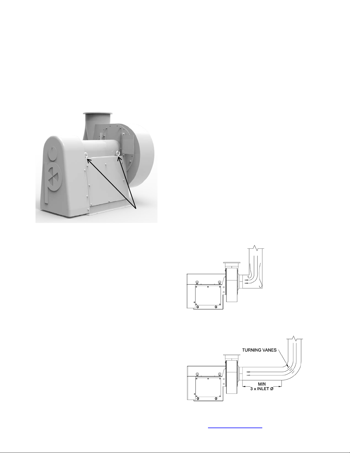
Drainage Detail
All CNW fans come with outlet drains due to water or
condensation that may accumulate. Proper disposal of the
water is necessary. Connect the drain outlet to a drainage
system (by others.) Piping must have adequate pitch for
proper runoff and be supported (if needed) to prevent the
possibility of sagging and overflow. The trap should be
filled before start-up.
“A” must be greater than system static pressure
“B” must be greater than ½ of the system static pressure.
“C” 1” water seal Figure 19
Drainage Detail
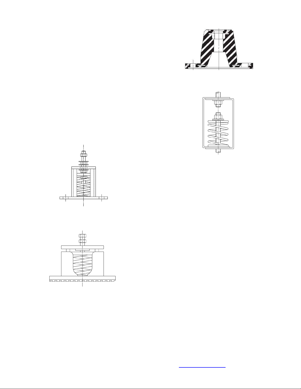
Fan Bearings
All CNW fans are equipped with solid pillow block bearings.
They are equipped with an integral set screw lock.
Fan Bearing Lubrication:
All CNW Fans use only Self-Lube pillow block bearings.
Bearings are factory charged with the correct amount of
grease and do not require further grease charge.
Re-lubrication is not required. See Figure 20.
Figure 20
Solid Pillow Block Bearing
Note: The motor bearing lubrication should be per the
motor manufacturer’s instructions.
Fan Bearing Replacement:
Fan bearing replacement intervals are defined by the fan
operator. M.K. Plastics does not define a schedule for
bearing replacement, as it is dependent on the
environment, usage and maintenance of each specific fan
installation. With proper installation, operation and
maintenance however, CNW bearings should last several
years. All CNW fans are equipped with NSK, RHP Self-
Lube cast iron pillow block units, NP or MP series.
Indicators that bearings need replacement include
excessive noise, vibration or heat in the vicinity of the
bearings.
In applications where contact with the exhaust poses a
serious contamination factor, the bearings can be removed
without removing the wheel and inlet cone. In this case, the
shaft must be held in place with suitable straps or bracings
firmly secured around the bearing support frame. The shaft
must be supported to restrict any lateral movement of both
the shaft and impeller.
Removal of Wheel, Shaft & Bearings:
1. Take note or make a sketch of the position on the
shaft of both bearing races, setscrews and the
wheel and sheave. If you are replacing the shaft
as well, these notes or sketch will give you
reference.
2. Mark the location and orientation of the inlet to
the casing and remove. Note the clearance
between the wheel and the inlet cone. This will
give you access to the wheel.
3. Remove the drive sheave from the shaft.
4. Start wheel removal by unscrewing the front
protective cap and then the nut, washers and
threaded stud assembly that holds the cap to the
fan shaft. Unscrew the setscrew collar. The wheel
can now be removed from the fan shaft. CNW
fans do not have bushings, the wheel is held in
place on the shaft with the threaded rod assembly,
the setscrew collar and key.
5. Remove the bearing housing mounting bolts and
remove the shaft and bearings as one unit. Keep
any existing shims in place.
6. The bearings are attached with set screws;
unscrew and slide the assembly off as one piece.
Tap on the bearing with a wood block and hammer
to remove if necessary.
7. If the existing shaft is being used, check the
shaft for nicks, burrs and damage. Remove any