manuals.online logo
Brands
  1. Home
  2. •
  3. Brands
  4. •
  5. M-S Cash Drawer
  6. •
  7. LCD Drawer
  8. •
  9. M-S Cash Drawer EP-125KLIC User manual

M-S Cash Drawer EP-125KLIC User manual

EP-125KLIC Instruction Manual
Installation
1. Electrical
Power to the cash drawer is supplied through a
small 12VDC 0.5 amp plug-in module similar to
those used by portable telephone equipment and
calculators. Use of this module removes a
possibility of electrical shock from the metal
drawer or components on the interface board
and protects any equipment connected to the
cash drawer from damage caused by accidental
contact with the 115VAC potential of wall power.
The female connector from the module plugs into
the jack at the rear center of the cash drawer.
Important Note:
When changing the settings of the switches on
the interface board, the power connector must
be removed. Switch settings are only read by the
interface at power-up. New settings will not be
effective until power is removed and reapplied.
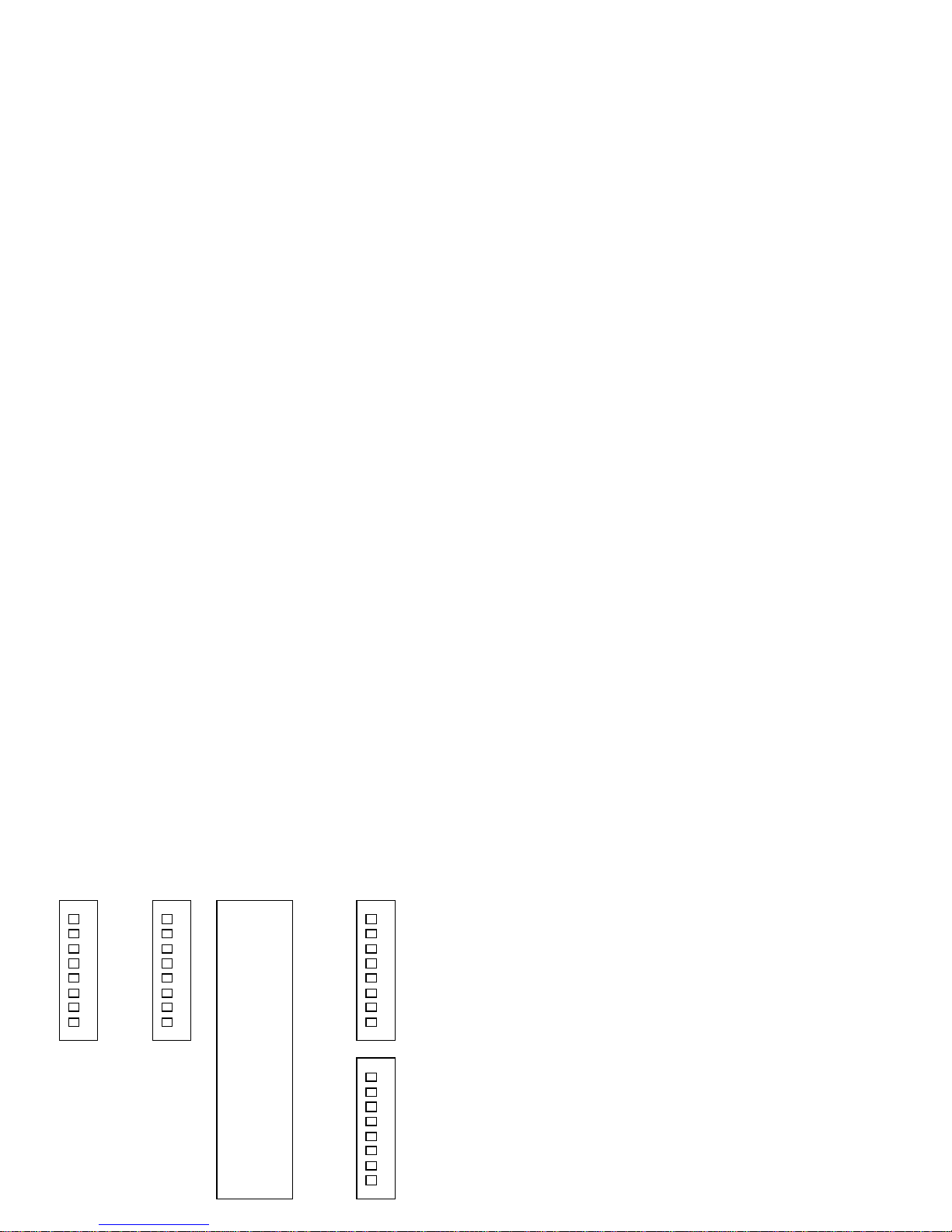
2. Configuring the Interface Board
The KLIC Universal Interface board supports all
three commonly used interface schemes for
communication to cash drawers. Selection of a
particular scheme is accomplished by setting four
banks of DIP (Dual In-line Package) switches on
the interface board located inside the cash
drawer on its rear panel. Access to the interface
board and the DIP switches is gained by
removing the plate at the rear of the cash
drawer.
Important Note:
Factory settings for the interface boards are
Dead End Serial mode operating at 1200 baud
using a drawer open signal of CONTROL G. If this
configuration meets your needs, no switch
settings need be changed. Charts showing
switch settings use “0” to indicate open/off and
“1” to indicate closed/on.
KLIC Switch Layout
To properly set the switches, you must know
which interface scheme you will be using. This
will be determined by the equipment available
on your computer or terminal, and any software
you are using with the cash drawer. The three
interface schemes are:
Serial – communication to the cash drawer is via
RS232 standard serial communication port
Parallel – communication to the cash drawer is
via parallel communication port
Pulse – drawer open command is supplied via a
voltage change from <2.5VDC to >3.5VDC.
Please skip to the heading that describes the
communication scheme you will be using.
Serial
Serial communication with the cash drawer
involves sending a unique drawer opening
character at a specific rate called the BAUD
rate. Any one of the standard ASCII character
codes may be used as a drawer opening
character as determined by preference or the
software being used.
CONTROL G (ASCII 7) is often used because it is
also the BEL character and many terminals emit a
short beep as the drawer opens. You may also
require an “ESC” prefix to the drawer opening by
setting switch 8 of bank 1 to on. This requires
that the “ESC” character immediately precede
your drawer opening character to be recognized
by the drawer.
Any of seven standard BAUD rates may be used.
Speed is not usually an important factor when
communicating with a cash drawer. So the
selection may be based on preference,
requirements of the software used, or
requirements of other equipment such as a
printer used in conjunction with the drawer.
Factory settings are for 1200 BAUD.
The third consideration for serial communication
is whether the cash drawer will be used in Dead
End mode or in Parasite mode. Using Dead End
mode means that the cash drawer is the only
device connected to the serial port. If you will
be using a printer, multiple cash drawers, or other
devices connected to the same serial port, use
the Parasite mode. * NOTE: When a cash drawer
is the last device in the chain it must be set in
Dead End mode.
Armed with the three pieces of information:
opening character, BAUD rate, and mode, you
SW2 SW1
SW3
SW4
8951
are ready to set the switches for serial
communication.
Serial Dead-End – No other device connected to
this serial port. Use the KLIC layout diagram to
locate switch banks.
Note: “0” indicates open/off
Bank #1 “1” indicates closed/on
Switch # 12345678
See ASCII/Timing Chart
Bank #2 *Baud Rate Chart
Switch # 12345678 Switch # Baud
***00000 123
Bank #3 111 19200
Switch # 12345678 011 9600
00000000
101 4800
Bank #4 001 2400
Switch # 12345678 110 1200
00011111 010 600
100 300
000 Not Used
Serial Parasite – A printer or other device is used
on this port. Use KLIC layout diagram to locate
switch banks.
Note: “0” indicates open/off
Bank #1 “1” indicates closed/on
Switch # 12345678
See ASCII/Timing Chart
Bank #2 *Baud Rate Chart
Switch # 12345678 Switch # Baud
***00000 123
Bank #3 111 19200
Switch # 12345678 011 9600
00000000
101 4800
Bank #4 001 2400
Switch # 12345678 110 1200
00011000 010 600
101 300
000 Not Used
Parallel
Parallel communication with the cash drawer
involves sending a unique drawer opening
character. Any one of the standard ASCII
character codes may be used as a drawer
opening character as determined by preference
or the software being used. A favorite is the
CONTROL G (ASCII 7). CONTROL G is often used
because it is also the bell character and many
terminals emit a short beep as the drawer opens.
You may also require an “ESC” prefix to the
drawer opening by setting switch 8 of bank #1 to
on. This requires that the “ESC” character
immediately precede your drawer opening
character to be recognized by the drawer.
The other consideration for parallel
communication is whether the cash drawer will
be used in Dead End mode or in Parasite mode.
Using Dead End mode means that the cash
drawer is the only device connected to the
parallel port. If you will be using a printer,
multiple cash drawers, or other devices
connected to the same parallel port, use the
Parasite mode. * NOTE: When a cash drawer is
the last device in the chain, it must be set in
Dead End mode.
Armed with these two pieces of information –
opening character and mode, you are ready to
set the switches for parallel communication.
Parallel Dead-End – No other device used on this
port. Use KLIC layout diagram to locate switch
banks.
Note: “0” indicates open/off
“1” indicates closed/on
Bank #1
Switch # 12345678
See ASCII/Timing Chart
Bank #2
Switch # 12345678
00011111
Bank #3
Switch # 12345678
11111111
Bank #4
Switch # 12345678
11100000
Parallel Parasite – A printer or other device is
used on this port. Use KLIC layout diagram to
locate switch banks.
Note: “0” indicates open/off
“1” indicates closed/on
Bank #1
Switch # 12345678
See ASCII/Timing Chart
Bank #2
Switch # 12345678
00000000
Bank #3
Switch # 12345678
11111111
Bank #4
Switch # 12345678
11100000
Pulse (Serial Mode)
Pulse communication with the cash drawer
involves sending a positive going pulse signal
from the computer on pin 2 (Transmit Data (TXD)).
The signal should be normally low (less then 2.5
volts) and should switch momentarily high to
greater than 3.5 volts to open the drawer.
Pulse Mode – No other device used on this port.
Use KLIC layout diagram to locate switch banks.
Note: “0” indicates open/off
“1” indicates closed/on
Bank #1
Switch # 12345678
See ASCII/Timing Chart
Bank #2
Switch # 12345678
00000000
Bank #3
Switch # 12345678
00000000
Bank #4
Switch # 12345678 Set ON to send drawer
00011000*
open/closed status to
computer on pin 6 Data
Set Ready (DSR).
3. Cabling
The host computer, terminal, or point of sale
device is connected to the cash drawer through
a standard RS232 cable, the same as those
commonly used to connect serial printers. Two
DB-25 connectors are provided on the rear panel
of the cash drawer – one male and one female.
Either connector may be used to communicate
with the host device and the other may be used
to optionally connect a printer or additional
drawers in daisy chain fashion.
Important Note:
The DB-9 connector is becoming increasingly
popular as a replacement to the DB-25 connector
for serial port applications. If you point of sale
device uses the DB-9 connector for serial port
output, it may be necessary to obtain an adapter
to the DB-25 form. These can be purchased from
M-S CASH DRAWER, your computer store, or an
electronics parts house such as RADIO SHACK.
See Appendix A for differences in pin-out.
4. Testing
A simple operational check of the KLIC interface
can be done in pulse mode. Set the switch banks
for pulse mode and apply a signal of 5VDC to
12VDC momentarily between pin 2 (positive) to
pin 7 (negative) of the interface cable. The
voltage source may be from the computer buss or
simply a small battery. This check will test the
KLIC’s computer, power circuitry, solenoid driver,
as well as the drawer circuitry. (Make sure the
12VDC plug-in adapter is connected and
powered.)
Important Note:
Be sure to close the drawer when performing
tests. The KLIC interface is smart enough not to
energize the solenoid if the drawer is already
open.
Serial Test Program
The following program is written in QBASIC for IBM
computers and compatibles. The program
provides all the commands necessary to set up
the serial port and send characters to the drawer
to test your drawer opening code.
10 CLS: INPUT “BAUD RATE?”;BAUD
20 CLS: KEY OFF:PRINT”READY…”:PRINT:LOCATE,,1
30 OPEN “COM1:”+STR$(BAUD)+”,E,7,1,CS,DS” AS #1
40 B$=INKEY$:IF B$<>””THEN PRINT #1,B$;
50 IF B$=”*” THEN END :REM ASTERISK TERMINATES
60 GOTO 40
Line 30 sets up the communications file.
COM1: Activates asynchronous communications
adapter 1
BAUD transmission bit rate-same as set on KLIC
interface
E use even parity
7 number of transmit data bits
1 number of stop bits
CS ignore Clear To Send (CTS) status
DS ignore Data Set Ready (DSR) status
MS-DOS Serial Test
Below is a test program to test the cash drawer
from a DOS prompt in Serial Dead-End mode on
COM1:.
Switches set to:
SW1: 1 1 1 0 0 0 0 0
SW2: 0 1 1 0 0 0 0 0
SW3: 0 0 0 0 0 0 0 0
SW4: 0 0 0 1 1 1 1 1
C:\> mode com1:9600,n,8,1 <Enter>
C:\> copy con COM1: <Enter>
^G ^Z <Enter>
^G – Hold Ctrl and press G
^Z – Hold Ctrl and press Z
Parallel Test Program
Below is a test program in QBASIC that can be
used to test the KLIC interface in parallel mode.
10 CLS: KEY OFF:PRINT “PARALLEL TEST READY…”
:PRINT:LOCATE,,1
20 OPEN “LPT1:” FOR OUTPUT AS #1
30 B$=INKEY$:IF B$<>”” THEN PRINT #1,B$
40 IF B$= ”*” THEN END : REM ASTERISK TERMINATES
50 GOTO 30
MS-DOS Parallel Test
Below is a test program to test the cash drawer
from a DOS prompt in Parallel Dead-End mode.
Switches set to:
SW1: 1 1 1 0 0 0 0 0
SW2: 0 0 0 1 1 1 1 1
SW3: 1 1 1 1 1 1 1 1
SW4: 1 1 1 0 0 0 0 0
C:\> copy con LPT1: <Enter>
^G ^Z <Enter>
^G – Hold Ctrl and press G
^Z – Hold Ctrl and press Z

Popular LCD Drawer manuals by other brands

Asko ODW8127S quick start guide

Asko

Asko ODW8127S quick start guide

Dacor MMD24S Service manual

Dacor

Dacor MMD24S Service manual

IOGear GCS1908W user manual

IOGear

IOGear GCS1908W user manual

Vox Lori 4013678 manual

Vox

Vox Lori 4013678 manual

Vivo DESK-AC03B instruction manual

Vivo

Vivo DESK-AC03B instruction manual

Intellinet 521796 user manual

Intellinet

Intellinet 521796 user manual

Lincat FWDG User instructions

Lincat

Lincat FWDG User instructions

New England Slimline 4 UW505 Assembly instructions

New England

New England Slimline 4 UW505 Assembly instructions

Bosch BVE9101B1 User manual and installation instructions

Bosch

Bosch BVE9101B1 User manual and installation instructions

Miele EVS 7010 Operating and installation instructions

Miele

Miele EVS 7010 Operating and installation instructions

KinAn LC2808 user manual

KinAn

KinAn LC2808 user manual

Altusen KL1508a user manual

Altusen

Altusen KL1508a user manual

Austin Hughes CyberView X124 user manual

Austin Hughes

Austin Hughes CyberView X124 user manual

ATEN KA8270 user manual

ATEN

ATEN KA8270 user manual

Acnodes KDS 6178 Specifications

Acnodes

Acnodes KDS 6178 Specifications

Viking Range VDUO5241 Installation, use & care manual

Viking Range

Viking Range VDUO5241 Installation, use & care manual

U-Line U-2275DWRCOL-00 installation guide

U-Line

U-Line U-2275DWRCOL-00 installation guide

STILFORD JBSLIMPDWE Assembly instructions

STILFORD

STILFORD JBSLIMPDWE Assembly instructions

manuals.online logo
manuals.online logoBrands
  • About & Mission
  • Contact us
  • Privacy Policy
  • Terms and Conditions

Copyright 2025 Manuals.Online. All Rights Reserved.