manuals.online logo
Brands
  1. Home
  2. •
  3. Brands
  4. •
  5. Mableaudio
  6. •
  7. Musical Instrument Amplifier
  8. •
  9. Mableaudio 5E3 User manual

Mableaudio 5E3 User manual

Popular Musical Instrument Amplifier manuals by other brands

AMT StoneHead-50-4 user manual

AMT

AMT StoneHead-50-4 user manual

Fender '63 Vibroverb owner's manual

Fender

Fender '63 Vibroverb owner's manual

Kuassa Amplifikation Vermilion user manual

Kuassa

Kuassa Amplifikation Vermilion user manual

Harley Benton GPA-100 quick start guide

Harley Benton

Harley Benton GPA-100 quick start guide

Cerwin-Vega CUM-3 user manual

Cerwin-Vega

Cerwin-Vega CUM-3 user manual

acus One Forstreet 10 quick start guide

acus

acus One Forstreet 10 quick start guide

Marshall Amplification MG10KK owner's manual

Marshall Amplification

Marshall Amplification MG10KK owner's manual

Pyle Pro PPG860A owner's manual

Pyle Pro

Pyle Pro PPG860A owner's manual

Crate Professional BV-120H user guide

Crate

Crate Professional BV-120H user guide

Laney BC30 user manual

Laney

Laney BC30 user manual

Vox Pathfinder 15SMR instruction manual

Vox

Vox Pathfinder 15SMR instruction manual

Marshall Amplification JVM205C brochure

Marshall Amplification

Marshall Amplification JVM205C brochure

Peavey Wiggy operating manual

Peavey

Peavey Wiggy operating manual

Fender Bassman 1200 operating instructions

Fender

Fender Bassman 1200 operating instructions

ZT Club owner's manual

ZT

ZT Club owner's manual

Ibanez IFS2X owner's manual

Ibanez

Ibanez IFS2X owner's manual

Crate GLX1200H user guide

Crate

Crate GLX1200H user guide

Laboga THE BEAST user guide

Laboga

Laboga THE BEAST user guide

manuals.online logo
manuals.online logoBrands
  • About & Mission
  • Contact us
  • Privacy Policy
  • Terms and Conditions

Copyright 2025 Manuals.Online. All Rights Reserved.

Mableaudio Company limited
Web: www.mableaudio.com
Tel:0086-755-83996326 fax:0086-755-83996326
Contact: Ms Mable [email protected]
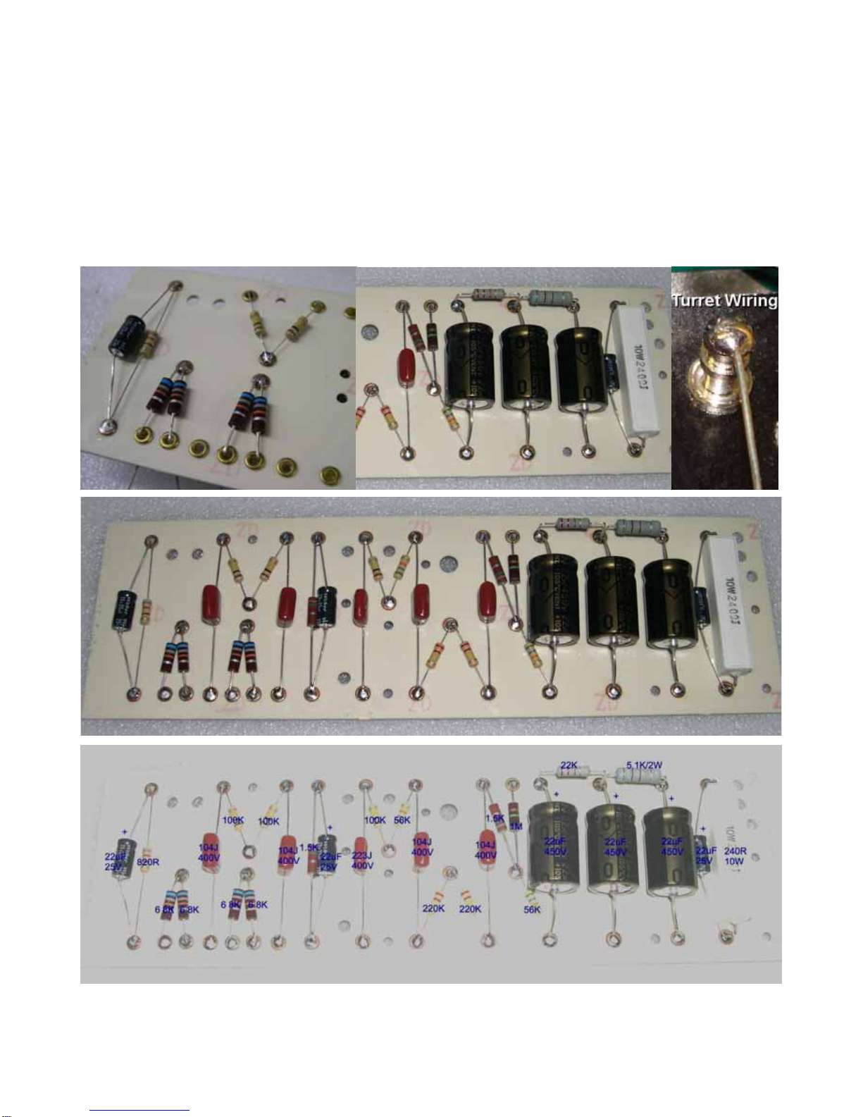
[5E3 assembly manual]
WARNING! This amp operates at voltages that may exceed 400V! Use extreme caution
when building and testing. If you are not comfortable working with high voltages, refer
assembly and testing to a qualified technician.
Neither the manufacturer nor the seller of this kit assume any responsibility for damages or
injuries incurred during assembly, testing, repair, or usage of this device.
Note: There are some minor variations between this 5E3 kit and the original Fender 5E3. Most of
these changes improve the noise and hum characteristics, and do not alter the tone or the sound in
any way. We have provided a schematic diagram at the end of this document. You can find the
original 5E3 schematic on many websites, if you wish to compare the two.
Recommended tools:
Screwdrivers -- Standard and Philips
Adjustable wrench (standard pliers will suffice)
Needle Nose Pliers
Diagonal Cutters
Wire Strippers
Soldering Iron -- 15 to 40 watt or temperature controlled solder station
High Power Soldering Iron or Gun – 100 watts or more
Solder
Multimeter -- AC/DC rated for at least 450V DC, resistance
Power Drill or Dremel rotary tool with grinder attachment, or a small to medium file
Eyelet Board and parts
Verify that you have all the necessary parts shown:
Board Assembly
Carefully install all parts in the positions shown in the bottom image below. Remember that electrolytic capacitors
(22uf/450v and 22uf/25v) are polarized and need to be placed in the direction shown.
Eyelet board (shown): Pull wires through the eyelets and solder. Cut excess wire from the other side of the
board. To make things easier, you can hold off on soldering until the wires are attached in the next step.
Turret board (see third image, top row): Position each component by running wires through the turrets and bend
wires as necessary. Remove the component and cut the wires so that only 1/8-1/4in. or 3-6mm is inside the turret.
Then reinsert the leads and solder.
Circuit Board Wiring
Tip: It may be easier to work with wire ends if you “tin” them first. Strip insulation off the end as needed. Then,
heat the wire with your soldering iron and touch solder to the wire just enough so the solder flows into the strands.
Don’t let the solder blob or glob onto the wire.
Solder wires in place as shown. Measure and cut each wire so that it hangs off the board by
the specified number of inches (1in = 25.4mm). It’s OK if you cut them longer than specified.
Excess will be cut off at final assembly.
If your board has turrets, attach the wires on the top of the board (component side) by stripping
3/8in or 9mm from the end of the wire, and then wrap the wire around the turret (see image to
the right). To solder, hold your soldering iron where it is touching both the wire and the turret
until solder flows and solder all the way around where the wire touches the turret.
Chassis Level assembly
Tip: Wear white cloth gloves when handling the chassis to avoid getting fingerprints on the chrome surface.
Check to see that all necessary parts are present.
Mount the two 9-pin mini sockets in the orientation shown, with the gap between Pin 1 and Pin 9 towards the top of
the chassis. Mount four ¼ in. jacks to the front of the chassis at this time as well. Next, twist two green wires
together as shown to make the filament wires. Solder one lead to Pin 9, and the other across Pins 4 and 5 of the
first preamp tube (12AY7). Your first segment will go from here to Pin 9 and Pins 4 and 5 of the second preamp
tube (12AX7).
Tip: Tight, consistent twists will make your amp operate quieter.
Twist and cut the second segment of green
filament wire to go from Pin 9 and Pins 4 and 5
of the second preamp socket (12AX7) to the
nearest output tube socket hole. Make sure it
is long enough to follow along the lip at the
bottom of the chassis.
Install two ¼ in. jacks into the next two holes in the rear of the chassis. Connect a black wire from Pin 1 on Jack B
to Pins 1 and 2 on Jack A. Connect a green wire from Pin 3 on Jack A to Pin 3 on Jack B,
Install a potentiometer into the first position (Pot 1) as shown. Take a .0047uf 630V capacitor and bend the leads
as shown below. Solder one lead to Pin 1, and leave the other lead along the back of the potentiometer to be
soldered later. Solder a short length of yellow wire to Pin 2.
Find the other two potentiometers. On each of them, bend Pin 1
back and solder it to the metal casing as shown.
Tip: To get solder to stick to a solid metal surface such as the
back of a potentiometer, it helps to “rough up” the surface first. You
can do this with a power drill or Dremel tool with a grinding
attachment. You can also use a file.
Install these potentiometers in the two open
positions (Pot 2 and Pot 3) and solder a
470pf capacitor from Pin 3 on Pot 1 to Pin 2
on Pot 2. Use a small piece of tubing, heat
shrink, or insulation stripped from a wire to
insulate the lead that goes to Pot 2 from
touching the grounded lead.
Solder the yellow wire from Pin 2 on Pot 1 to
Pin 3 on Pot 2.
Install two threaded standoffs to the chassis for circuit board mounting
Install two rubber grommets for the output transformer wires to pass through
Install the output transformer with the green and black leads towards the output jacks. Run the wires through the
grommets, and pull them towards the rear of the chassis to keep them out of the way of the circuit board.
Note: If you wish, you may hold off on installing the output transformer until later. This will make it easier to
complete the next few steps, but it will be more difficult to bolt the transformer down if you do it this way.
Make sure that all the wiring on the back side of the circuit board is correct before proceeding to the next
step! Any errors made will be extremely difficult to repair after the board is wired in.
Before installing the circuit board, make sure that all of the wires are bent upwards, so none of them become
buried under the board. Align the two screw holes with the standoffs and carefully screw the board down. Don’t
force the screws if the board doesn’t want to go all the way into place.