Installations- und Betriebsanleitung USV-Modul (480987)
WARNUNG!
Vor der Montage und
Installation des Gerätes
lesen Sie diese Anleitung
komplett durch.
Vergewissern Sie sich,
dass Sie diese verstanden
haben.
Die Gerätebeschriungen
beachten!
Bei Einzelentnahme muss der Beipackzettel
dem Einzelteil hinzugefügt werden.
Bei Bedarf können Sie den Beipackzettel von der
MACO-Homepage (www.maco.eu) herunterladen!
ACHTUNG!
Sicherheitshinweise
Beim Betrieb dieser Stromversorgung stehen bestimmte Teile dieses
Gerätes unter gefährlicher Spannung.
Nicht sachgemäßer Umgang mit diesen Geräten kann deshalb zu Tod
oder schweren Körperverletzungen sowie zu erheblichen Sachschäden
führen. Das Gerät darf nicht von Personen (einschließlich Kindern -
auch unter Aufsicht) mit eingeschränkter körperlicher, sensorischer
oder geistiger Leistungsfähigkeit verwendet werden.
Funktionsbeschreibung
Das Puermodul dient zur 24 V Versorgung während eines Netzausfalls. Die darin bendlichen Lithium-Eisen-Phosphat-
Akkus werden von dem 24 V Netzteil geladen. Im Falle eines Spannungsausfalls übernimmt das Modul die Versorgung.
Durch umfangreiches Akkumanagement sowie Schutz und Überwachungsfunktionen kann das Modul einfach an die
24 V Versorgung ohne weitere Sicherungselemente angesteckt werden. Es sind keine Einstellungen und dgl. erforder-
lich. Im Auslieferungszustand ist das Modul spannungsfrei. Erst wenn bei der erstmaligen Inbetriebnahme 24 V über das
Netzteil zugeführt werden beginnt der Regelbetrieb des USV-Moduls.
Installations- und Montagehinweise
Die Puermodule sind Einbaugeräte mit Schutzart IP40. Ein übergeordnetes Berührschutzgehäuse ist erforderlich.
Für die Installation der Geräte sind die einschlägigen EN/IEC-Bestimmungen oder die länderspezischen Vorschrien zu
beachten. Insbesondere ist vor Beginn der Installations-, Demontage- oder Instandhaltungsarbeiten der Hauptschalter
der Anlage auszuschalten und gegen Wiedereinschalten zu sichern.
Nur entsprechend qualiziertes Fachpersonal darf das Gerät installieren und in Betrieb
nehmen. Der einwandfreie und sichere Betrieb dieses Gerätes setzt sachgemäßen Trans-
port, fachgerechte Lagerung, Aufstellung, Montage und Installation voraus.
Insbesondere sind dazu die Angaben dieser Anleitung zu beachten.
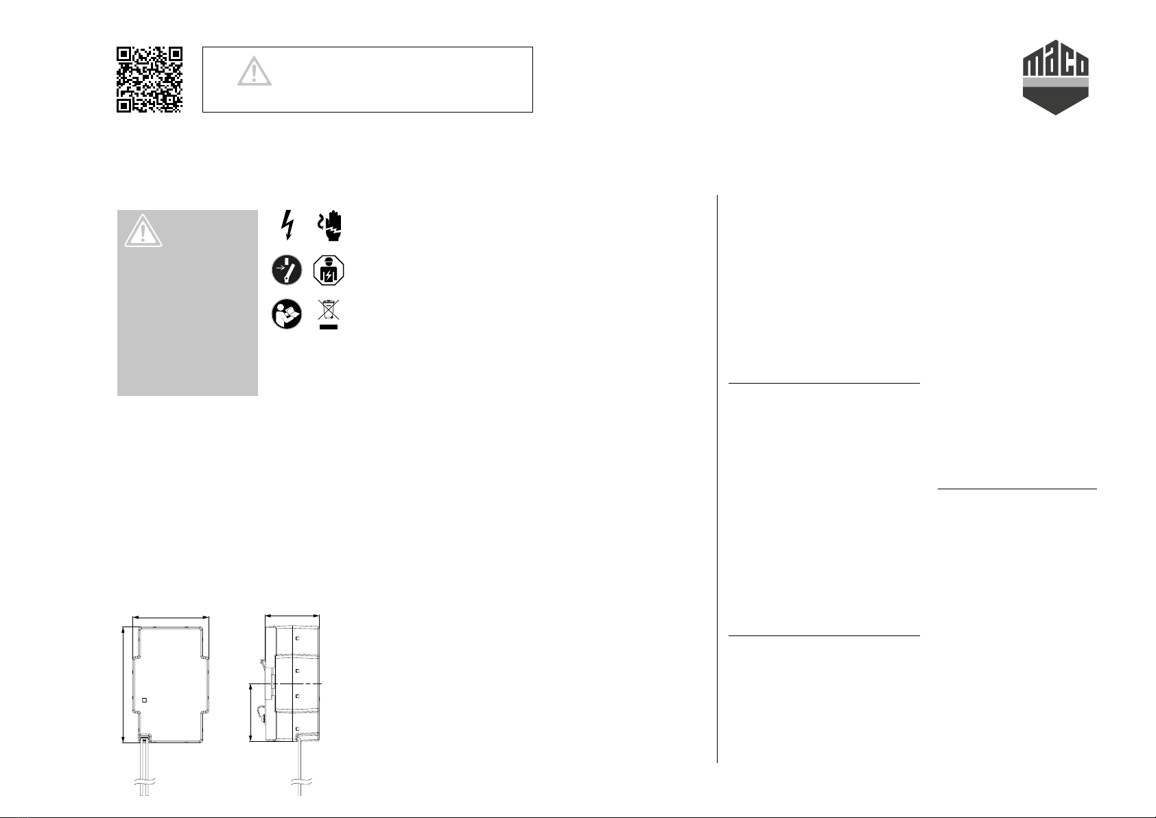
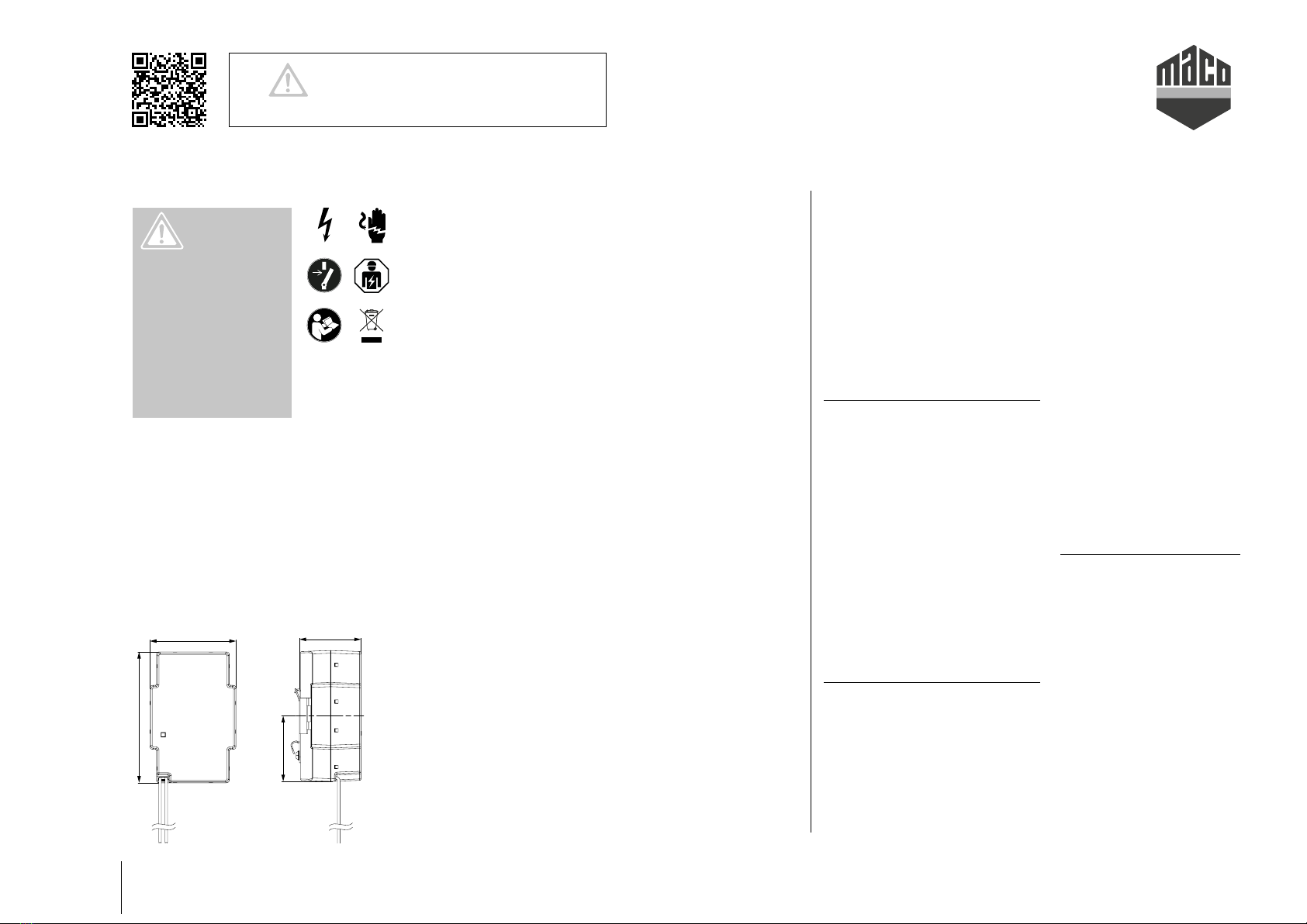
45,5
Die Montage erfolgt auf Normprolschiene DIN EN 60715-TH35-15/7,5.
Alternativ kann das Gerät auch in Unterputz- oder Hohlwanddosen
montiert werden. Dazu kann die Montageklammer auf der Rückseite des
Gerätes durch das Lösen der beiden Schrauben abgenommen werden.
Anschluss nur an 24 V DC Versorgungsspannung (SELV/ES1 Quelle
gemäß IEC 62368-1).
Das versorgende Netzteil muss die auretenden Transienten auf 1500 V
begrenzen.
Das Gerät darf nicht im Hausmüll entsorgt, sondern muss separat
gesammelt werden!
Technische Daten
Eingangsdaten:
Eingangsspannung
24 V ± 1 V, DC
Arbeitsspannung im Puerfall
24 V ± 1 V, DC
Eingangsstrom bei entladenen Akkus
~ 0,2 A
Ladezeit
~ 5 h
Ausgangsdaten:
Arbeitsspannung im Puerfall
24 V ± 1 V, DC
Kapazität
900 mAh / 24 V, DC
Maximale Lastströme
~ 7 A für max. 100ms
3 A für max. 500ms
0,7 A für max. 30 Minuten
0,5 A statisch
Puerzeit bei vollem Akku typ.
20 mA Laststrom ca. 25 h
100 mA Laststrom ca. 6 h 40 min
500 mA Laststrom ca. 1 h 20 min
Gewicht
(ca.) 290 g
Vorschrien:
Sicherheit
Schutzart: IP20 nach IEC 60529
IEC 62368-1:2014
EMV
› Störaussendung
Standard EN 61000-6-3 / -6-4
EN 55011/22 Class B
› Störfestigkeit
Standard EN 61000-6-1 / -6-2
Weitere Schutzfunktionen
› Dauerkurzschlussfest
› Überlastfest
› Übertemperaturüberwacht
› Serviceabschaltung bei
Last < 20 mA
› Akkuzellen sind einzelnen gegen
Überladung und Tiefentladung
überwacht und geschützt
Anzeige
LED grün
blinkend: Akku wird geladen
LED grün: Akku > 90 % geladen
LED gelb
blinkend: Puerbetrieb
Umgebung:
Temperatur
Für Lagerung und
Transport: -20 … +55 °C
Für Betrieb: 0 … 40 °C
max. Seehöhe
im Betrieb: 4000 m
Konvektionsselbstkühlung
Anschluss
2 Adern zur Verbindung mit
Netzteil und den zu versorgenden
Komponenten:
› rot: +24 V DC
› schwarz: GND
Zulassungen
CE Kennzeichnung


 Plus Startup manual")


