MetaSystem Whad 1500 User manual
IT
EN
FR
DE
PT
Manuale d’uso per l’utente
User’s Manual
Manuel d’installation et d’utilisation
Bedienungsanleitung für den Benutzer
Manual do utilizador
Whad 1500 - 2000- 2500
GRUPPI DI CONTINUITÀ
UNINTERRUPTIBLE POWER SUPPLIES
ONDULEURS
UNTERBRECHUNGSFREIEN
STROMVERSORGUNGEN
V81608A
V81608A Ist.Uso Whad2000:V81608A Ist.Uso UPS Whad2000 8-04-2008 9:52 Pagina 1

2
Dichiarazione CE di conformità
Direttive del consiglio applicate: 73/23/CEE; 89/336/CEE modificata con le direttive
92/31/CEE, 93/68/CEE
Standard al quale si dichiara la conformità: EN 62040-1-1, EN 50091-2, EN 62040-3
Costruttore: MetaSystem S.p.A.
Indirizzo: via Majakovskij, 10/b Reggio Emilia, Italia
Tipo di apparecchiatura: Gruppo di Continuità
Modelli: Whad 1500 - Whad 2000 - Whad 2500
Anno di apposizione del marchio: 2007
L’apparecchiatura è stata provata nella configurazione tipica di installazione e con periferiche conformi
alle Direttive sopra elencate.
Io sottoscritto dichiaro che l’apparato sopra definito soddisfa i requisiti delle Direttive sopra specificate.
Reggio Emilia, 21/05/07 Ing. Cesare Lasagni
Direttore Tecnico
MetaSystem si riserva il diritto di apportare, senza preventiva comunicazione, variazioni alle specifiche qui
sopra riportate.
©Copyright by MetaSystem
INDICE
Dichiarazione di conformità CE . . . . . . . . . . . . . . . . . . . . . . . . . . . . . . . . . . . . . . . . . . . . . . . . . .pag.2
Condizioni d’uso . . . . . . . . . . . . . . . . . . . . . . . . . . . . . . . . . . . . . . . . . . . . . . . . . . . . . . . . . . . .pag.3
Installazione . . . . . . . . . . . . . . . . . . . . . . . . . . . . . . . . . . . . . . . . . . . . . . . . . . . . . . . . . . . . . .pag. 4
Funzioni e segnalazioni . . . . . . . . . . . . . . . . . . . . . . . . . . . . . . . . . . . . . . . . . . . . . . . . . . . . . . .pag. 4
Software autodiagnostico UPS SuperviSor light . . . . . . . . . . . . . . . . . . . . . . . . . . . . . . . . . . . . . .pag. 5
Impostazione Funzioni speciali . . . . . . . . . . . . . . . . . . . . . . . . . . . . . . . . . . . . . . . . . . . . . . . . .pag. 6
Test batterie . . . . . . . . . . . . . . . . . . . . . . . . . . . . . . . . . . . . . . . . . . . . . . . . . . . . . . . . . . . . . . .pag. 6
Possibili problemi e loro risoluzione . . . . . . . . . . . . . . . . . . . . . . . . . . . . . . . . . . . . . . . . . . . . . .pag. 7
Caratteristiche tecniche . . . . . . . . . . . . . . . . . . . . . . . . . . . . . . . . . . . . . . . . . . . . . . . . . . . . . .pag. 8
IT
V81608A Ist.Uso Whad2000:V81608A Ist.Uso UPS Whad2000 8-04-2008 9:52 Pagina 2
Congratulazioni per la Vostra scelta!
Questo manuale contiene le informazioni di sicurezza, installazione e funzionamento relative ai gruppi di con-
tinuità serie Whad prodotti da MetaSystem.
Gli UPS della serie Whad sono realizzati prevalentemente per uso civile, industriale ed elettromedicale; tutta-
via, in quest’ultimo caso, occorre accertarsi se, nel paese di utilizzo, esistano particolari normative in merito.
In caso di problemi con l’UPS, si consiglia di leggere questo manuale prima di contattare il servizio di assi-
stenza tecnica; la sezione “Possibili problemi e loro risoluzione”, infatti, può aiutare a risolvere la maggior
parte degli inconvenienti incontrati durante l’utilizzo del gruppo di continuità.
Importante
Si consiglia di conservare i materiali per l’imballaggio dell’apparecchiatura, in quanto potrebbero risultare
molto utili per un eventuale invio in riparazione.
CONDIZIONI D’USO
•L’UPS è stato progettato per alimentare apparecchiature per elaborazione dati, il carico applicato non deve
superare quello indicato sull’etichetta posteriore dell’UPS.
•Il pulsante ON/OFF dell’UPS non isola elettricamente le parti interne. Per isolare l’UPS, scollegarlo dalla
presa di alimentazione di rete.
•Non aprire il contenitore dell’UPS, in quanto, all’interno, vi possono essere parti a tensione pericolosa anche
con spina di rete scollegata; comunque all’interno non sono presenti parti riparabili dall’utente.
•Il pannello frontale di controllo è previsto per operazioni manuali; non premere sul pannello con oggetti af-
filati o appuntiti.
• L’UPS è stato progettato per funzionare in ambienti chiusi, puliti, privi di liquidi infiammabili e di sostanze
corrosive e non eccessivamente umidi.
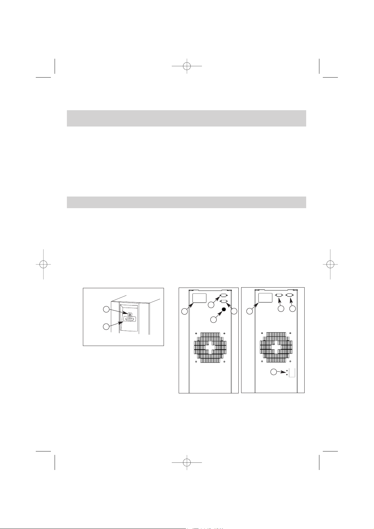
LEGENDA
1PULSANTE DI ACCENSIONE E SPEGNIMENTO
2INDICATORE STATO DI FUNZIONAMENTO
(verde/giallo/rosso)
3PRESA-SPINA D’INGRESSO/USCITA
4 PRESA INTERFACCIA LIVELLI LOGICI
5PRESA INTERFACCIA COMPUTER RS232
6CONNETTORE PER COLLEGAMENTO UNITA’ BATTERIE
SUPPLEMENTARE (UPS Whad 2000 - UPS Whad 2500)
7INTERRUTTORE AUTOMATICO RIPRISTINABILE (UPS Whad 1500)
Si consiglia di leggere attentamente questo manuale prima di procedere all’installazione del gruppo di
continuità, attenendosi scrupolosamente a quanto di seguito riportato.
I danni arrecati dal trasporto a causa di un cattivo imballaggio dell’UPS non sono coperti da garanzia.
3
Fig.2
3
Fig.1
2
1
Fig.3
4
6
5
3
5
7
4
UPS Whad 1500
UPS Whad 2000-2500
V81608A Ist.Uso Whad2000:V81608A Ist.Uso UPS Whad2000 8-04-2008 9:52 Pagina 3

AVVERTENZA
Per motivi di sicurezza si consiglia di non modificare i cavi forniti, inoltre è necessario assicurarsi che la presa
di rete a cui si collega il gruppo di continuità abbia una sicura connessione al circuito di terra.
AVVERTENZA
La presa di alimentazione di rete, o il dispositivo di sezionamento, devono essere installati in prossimità del-
l’apparecchiatura e devono essere facilmente accessibili.
Procedere all’installazione nel modo seguente:
1) Posizionare il gruppo di continuità in modo che le feritoie di ventilazione non risultino ostruite.
2) Collegare al connettore di Ingresso-Uscita [3] il cavo di alimentazione e la presiera multipla di uscita (vedi
fig. 2).
3) Collegare i carichi alla presiera di uscita, verificando che gli interruttori dei vari utilizzatori siano spenti.
4) Collegare la spina di alimentazione ad una presa di corrente adeguata alla tensione e alla corrente richie-
ste.
Accensione
1) Accendere il gruppo di continuità con l’apposito pulsante [1] (si veda il paragrafo “Funzioni e segnalazioni”
alla voce “comandi”); inizialmente l’UPS alimenterà l’uscita direttamente dalla rete tramite il by-pass (se-
gnalazione del led giallo [2]) per poi commutare a inverter dopo alcuni secondi ed entrare nel modo nor-
male di funzionamento (è acceso il led verde MAINS [2]).
2) Accendere i carichi e verificare che, dopo l’eventuale intervento del by-pass, si abbia il ritorno al funziona-
mento normale; a questo punto è acceso il led verde MAINS [2]. Nel caso i carichi collegati risultino ec-
cessivi, rimarrà inserito il by-pass e lampeggerà il led rosso ALARM [2].
3) Qualche istante dopo l’accensione, il gruppo di continuità esegue automaticamente il test delle batterie,
per verificarne il corretto funzionamento (vedi paragrafo “Test Batterie”).
FUNZIONI E SEGNALAZIONI
Segnalazioni luminose:
Con riferimento alla figura a pagina 3, l’indicatore luminoso [2] ha le seguenti funzioni:
• Led verde MAINS
•acceso: rete regolare, inverter sincrono.
•lampeggiante: rete fuori tolleranza, ma presente e sufficiente per il corretto funzionamento, oppure
inverter non sincrono.
•spento: rete assente o troppo bassa in relazione al carico.
ATTENZIONE
Poichè le correnti di dispersione verso terra di tutti i carichi si sommano nel conduttore di protezione (filo di
terra) dell’UPS, per motivi di sicurezza, come da norma EN 62040-1-1, occorre assicurarsi che la somma di
queste correnti non superi il valore di 2.7 mA.
ATTENZIONE
Se dopo l’accensione di tutti i carichi collegati, si nota un lampeggio breve ogni 3 secondi del led rosso
ALARM, significa che il carico connesso all’UPS é al limite massimo consentito.
AVVERTENZA
Non disinserire mai la spina di alimentazione 230V mentre l’UPS è in funzione, in quanto questa operazione
scollega la terra di protezione sia dall’UPS che dai carichi ad esso connessi.
INSTALLAZIONE
Nel retro del gruppo di continuità sono predisposti i seguenti collegamenti:
• Presa-spina di Ingresso-Uscita [3]: collegare a questo connettore il cavo di alimentazione e la presiera di
uscita come indicato in figura.
• Presa per collegamento interfaccia seriale computer tipo RS232 (9 poli femmina) [5]: da utilizzarsi nel caso
si voglia sfruttare il software autodiagnostico UPS SuperviSor light.
• Presa per collegamento interfaccia livelli logici [4].
4
V81608A Ist.Uso Whad2000:V81608A Ist.Uso UPS Whad2000 8-04-2008 9:52 Pagina 4

5
• Led giallo BATTERY
• acceso: funzionamento a batteria.
• lampeggiante: riserva batterie o fine autonomia o test batterie negativo.
• spento: funzionamento a rete.
• Led rosso ALARM
• acceso: blocco del funzionamento dell’UPS.
• lampeggiante: guasto di un modulo di potenza.
• lampeggio alternato breve-lungo: collegamento errato del conduttore di neutro in ingresso (con sensore
di neutro abilitato).
• spento: funzionamento normale.
• acceso: anomalie nella tensione di uscita.
• lampeggiante: sovraccarico.
• spento: funzionamento normale.
• lampeggio breve ogni 3 sec.: preavviso di sovraccarico.
• Led giallo BY-PASS
• acceso: by-pass attivo (uscita alimentata direttamente dalla rete).
• spento: uscita alimentata dall’inverter.
Segnalazioni acustiche:
• Suono continuo: UPS in blocco.
• Suono intermittente lento (un bip ogni 12 secondi): funzionamento a batteria.
• Suono intermittente veloce: sovraccarico o guasto.
• Suono intermittente alternato breve-lungo: riserva autonomia o test batterie negativo o errata connessione
del conduttore di neutro (con sensore di neutro abilitato).
• Bip singolo: segnalazione accensione dell’UPS o riconoscimento richiesta test batterie o fine test batterie
con esito positivo.
Comandi:
Il gruppo di continuità viene gestito tramite il pulsante sul frontale, visibile in figura a pagina 3.
1 Pulsante di accensione/spegnimento:
• Premendo brevemente si ha l’accensione dell’UPS evidenziata dall’accensione momentanea del led [2]
e da una breve segnalazione acustica (bip).
• Tenendo premuto lo stesso pulsante per circa due secondi si ha lo spegnimento dell’UPS, evidenziato dal
suono intermittente del buzzer.
Avvertenze:
• In condizioni di funzionamento normale è acceso il LED verde MAINS [2].
• Durante il funzionamento a batteria è acceso il led giallo BATTERY [2].
• Il funzionamento a batteria è segnalato da un avviso acustico a cadenza lenta (un bip ogni 12 secondi). La
riserva autonomia, cioè il momento opportuno per chiudere le procedure avviate dall’utente su di un com-
puter collegato al gruppo di continuità, è indicata da una segnalazione acustica intermittente alternata breve-
lunga, accompagnata da un uguale lampeggio del led BATTERY [2]. Il fine autonomia é segnalato dal
lampeggio del led giallo “BATTERY” e dal suono continuo del cicalino, per durata di 15”; in questa condi-
zione il carico non è più alimentato.
• Il lampeggio del LED rosso ALARM indica la presenza di un carico eccessivo in uscita.
In tal caso, se la rete è presente, il carico viene alimentato da quest'ultima tramite il by-pass, diversamente
l’UPS va in blocco dopo 15 secondi di sovraccarico continuativo. Il lampeggio del LED rosso ALARM [2] in-
dica il guasto di un modulo di potenza se l’intermittenza è rapida; una anomalia nel collegamento del gruppo
di continuità (collegamento del conduttore di neutro errato) se l’intermittenza è di tipo alternato breve-lungo.
Nel caso di neutro errato invertire il verso di inserimento della spina del cavo di alimentazione dell’UPS.
• In caso di blocco dell’UPS per una qualsiasi anomalia si ha lo spegnimento automatico e completo dopo
circa 15 secondi.
V81608A Ist.Uso Whad2000:V81608A Ist.Uso UPS Whad2000 8-04-2008 9:52 Pagina 5
SOFTWARE AUTODIAGNOSTICO UPS SuperviSor light
L’UPS è corredato da un software per ambienti Windows (16 e 32 bit) denominato UPS SuperviSor light.
Questo software implementa le funzioni di:
- Visualizzazione di tutti i dati di funzionamento e diagnostica in caso di problemi.
- Impostazioni delle funzioni speciali.
- Shutdown automatico del computer locale (con sistema operativo Windows).
Per scaricare gratuitamente una copia del software e/o per ottenere un elenco dettagliato dei sistemi sup-
portati visitare il sito Internet www.metasystem.it.
Windows è un marchio registrato della Microsoft Corporation.
Connessione
L’UPS é dotato di interfaccia standard RS232, grazie alla quale é possibile accedere, tramite un elaboratore,
ad una serie di dati relativi al funzionamento e alla storia dell’UPS. La funzione é utilizzabile tramite il pro-
gramma di interfacciamento UPS SuperviSor light per ambiente WINDOWS (*), connettendo una porta seriale
del PC alla presa di interfacciamento [5] presente sul retro dell’UPS, tramite un cavo RS 232.
È inoltre possibile configurare l’UPS abilitando o disabilitando alcune funzioni speciali (Hardware).
6
IMPOSTAZIONE FUNZIONI SPECIALI
1 - Neutral sense: Il sensore di neutro è in grado di inibire il funzionamento dell'UPS nel caso in cui il potenziale di
neutro si discosti eccessivamente da quello di terra.
2 - Autorestart: Questa funzione, permette di ottenere la riaccensione automatica dell'UPS al ritorno della rete dopo
ogni blocco per fine autonomia.
3 - Dip speed: Questa funzione è stata inserita per l'utilizzo con carichi che presentano spunti brevi e ripetuti (ad esem-
pio le stampanti laser). Con il suo inserimento, l'intervento del by-pass viene ritardato di 10 ms consentendo all'UPS
di superare gli spunti più brevi senza il suo intervento.
4 -Extended pll lock range: Permette di ampliare la gamma di aggancio della frequenza di rete da ±1Hz a ±10Hz.
5 - Load waiting mode enable (attesa carico): Il gruppo di continuità può essere configurato per funzionare in "load
waiting mode" (LWM). Questo particolare tipo di funzionamento consente di ottenere l'attivazione e lo spegnimento
automatici dell'UPS in base all'accensione del carico collegato.
6 - Funzionamento a 60Hz: Il gruppo di continuità può essere configurato per funzionare con tensione di linea a 60Hz.
Per maggiori dettagli su queste funzioni e altre di importanza minore, fare riferimento all’Help in linea del soft-
ware di diagnostica UPS SuperviSor light.
TEST BATTERIE
Il test delle batterie può essere eseguito durante il funzionamento a rete nei seguenti modi:
1. Automaticamente, dopo opportuna programmazione tramite software opzionale di shutdown.
2. Ad ogni accensione dell’UPS tramite software UPS SuperviSor light.
Il test è eseguito in modo di funzionamento a rete (cioè senza commutazione forzata a batteria), grazie ad un
particolare circuito brevettato da MetaSystem; pertanto anche in caso di test con esito negativo non si hanno
interruzioni della tensione di uscita.
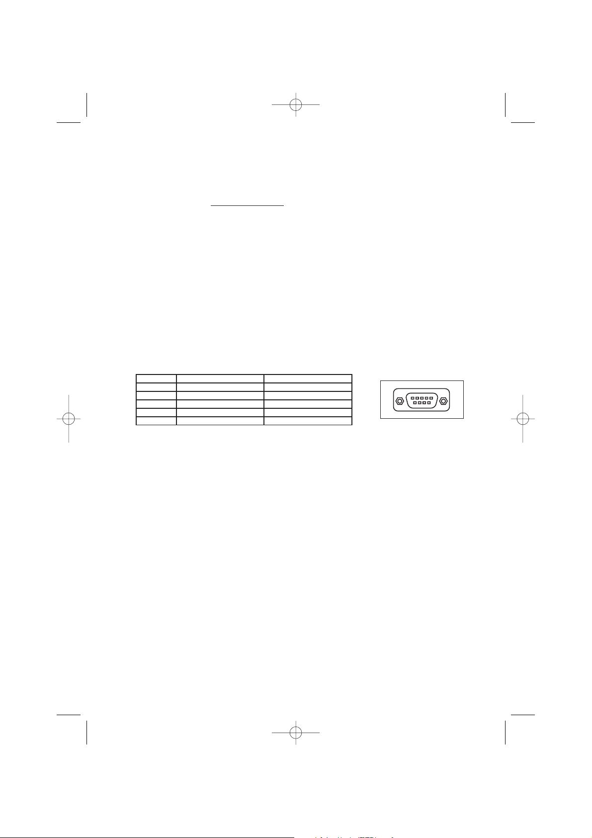
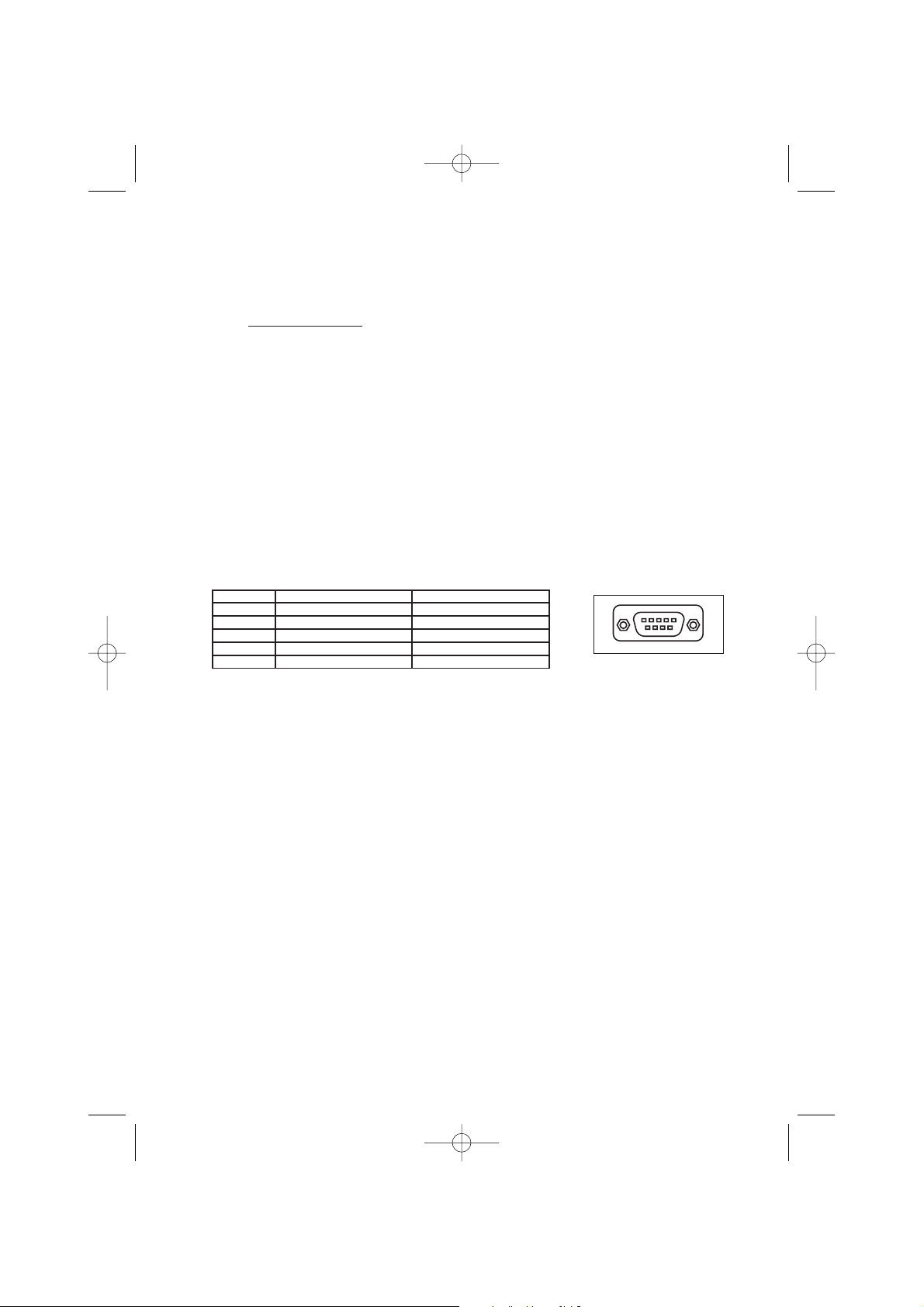
Interfaccia Contatti (UPS WHAD 1500)
I contatti presenti nell’interfaccia relè sono programmati di default come Normalmente Aperti (NA)
Le caratteristiche tecniche della porta a contatti sono le seguenti:
IMAX = 5A VMAX = 50VAC – 30VDC (per i contatti 1-6, 2-7, 3-8)
Le segnalazioni disponibili mediante l’interfaccia contatti puliti, indicando con N.1 il primo contatto partendo
dal lato sinistro del connettore, sono le seguenti (vedere Fig.4):
PIN FUNZIONE TIPO DI CONTATTO
1-6 Funzionamento a batteria Dry Contact Relay NA
2-7 Riserva Autonomia Dry Contact Relay NA
3-8 Allarme generico Dry Contact Relay NA
4-9 Not Connected Not Connected
5Not Connected Not Connected Fig.4
15
69
V81608A Ist.Uso Whad2000:V81608A Ist.Uso UPS Whad2000 8-04-2008 9:52 Pagina 6

7
POSSIBILI PROBLEMI E LORO RISOLUZIONE
Problemi Soluzioni
• All’accensione l’UPS fa suonare il cicalino e lam-
peggiare il led rosso ALARM con intermittenza di
tipo alternato breve-lungo, quindi si spegne dopo
15 secondi.
• L’UPS funziona ma ogni 12 secondi emette un
breve segnale acustico ed é sempre acceso il led
giallo BATTERY.
• L’UPS funziona ma emette un segnale acustico in-
termittente e lampeggia il led rosso ALARM + LED
giallo BY PASS fisso.
• L’UPS emette un segnale acustico costante ed é
acceso il led giallo BATTERY lampeggiante per circa
15 secondi, dopo di che il gruppo si spegne.
• L’UPS funziona ma il led verde MAINS lampeggia
in modo rapido.
• L’UPS emette un segnale acustico intermittente e
il LED rosso ALARM lampeggia in modo rapido.
- È errato il collegamento del conduttore di neutro:
girare la spina di alimentazione, oppure esclu-
dere sensore di neutro (tramite software UPS
SuperviSor light in dotazione).
- Assicurarsi della presenza di tensione nella presa
di rete.
- Controllare il perfetto inserimento del cavo di ali-
mentazione del gruppo di continuità sia nella
presa di rete che nel connettore del gruppo
stesso.
- È presente un sovraccarico dell’uscita dell’UPS.
Ridurre il numero di apparecchiature collegate in
modo che il carico non superi la massima po-
tenza erogabile dal gruppo di continuità.
- Il gruppo ha scaricato completamente le batterie,
può ripartire solo se la linea d’ingresso é pre-
sente. Controllare gli interruttori magneto-termici
o differenziali a monte del gruppo
- La rete è fuori dai limiti consentiti come tensione
e/o come frequenza, ma pur sempre utilizzabile
dall’UPS. Non è però disponibile la funzione di
by-pass.
- È intervenuta la protezione termica. Spegnere il
gruppo di continuità e attendere qualche minuto
in modo che la temperatura interna dell’UPS si
normalizzi. Verificare il corretto funzionamento
della ventola e che il relativo flusso d’aria non
sia ostacolato (ad es. gruppo troppo vicino ad
una parete).
- È avvenuto un guasto in qualche circuito interno.
Contattare il più vicino centro di assistenza.
Se durante la condizione di guasto non si accendono i LED ALARM e/o by pass, l’UPS é in grado di
funzionare regolarmente seppur con potenza ridotta.
V81608A Ist.Uso Whad2000:V81608A Ist.Uso UPS Whad2000 8-04-2008 9:52 Pagina 7

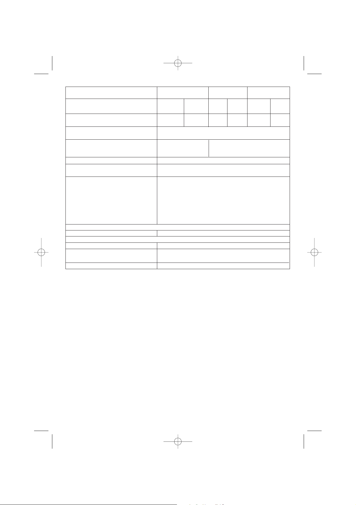
CARATTERISTICHE TECNICHE
8
Specifiche costruttive Whad 1500 Whad 2000 Whad 2500
Pesi 25 Kg
Dimensioni L x H x P in mm 160 x 460 X 420
Tecnologia PWM ad alta frequenza sia per lo stadio di ingresso che per
quello di uscita. Logica di controllo a microprocessore.
Interfaccia computer
Seriale RS232 standard per interfacciamento con personal
computer tramite software autodiagnostico in dotazione,
uscita su connettore a vaschetta a 9 poli femmina isolato SELV.
Protezioni Elettroniche contro sovraccarichi, cortocircuito ed eccessiva
scarica delle batterie.
Blocco del funzionamento per fine autonomia.
Limitatore di spunto all’accensione.
Sensore di corretto collegamento del neutro.
Back-feed protection (isolamento elettrico di sicurezza della
spina d’ingresso durante il funzionamento a batteria).
By-pass sincronizzato interno Automatico
Intervento per sovraccarico e anomalia di funzionamento
Specifiche ambientali
Altitudine massima di immagazzinamento 1000 metri
Gamma di temperatura di immagazzinamento da -20°C a +50°C
Gamma di temperatura per il funzionamento
da 0°C a 40° C
Gamma umidità relativa per il funzionamento da 20% a 80% non condensante
Grado di protezione come da IEC529 IP21
Rumore acustico a 1 metro
42 dBA
Caratteristiche elettriche di ingresso
Tensione nominale di ingresso
230V
Gamma della tensione di ingresso (carico nominale) da 184V a 265V da 184V a 264V
Gamma della tensione di ingresso (50% carico nominale) da 100V a 265V da 110V a 264V
Frequenza nominale di ingresso (
selezionabile dall’utente) 50Hz/60Hz +/-5% 50Hz/60Hz +/-2%
Corrente nominale di ingresso 5,3 A rms 7,4 A rms 9,2 A rms
Corrente massima di ingresso 6,8 A rms 9 A rms 11,4 A rms
Distorsione della corrente di ingresso
<3% <10%
con carico nominale
Fattore di potenza di ingresso
>0.99 all’80% del carico nominale
Corrente di spunto
100% della corrente nominale
Numero delle fasi di ingresso
Monofase
Fusibile di linea Automatico
20 A FF
ripristinabile 20A
V81608A Ist.Uso Whad2000:V81608A Ist.Uso UPS Whad2000 8-04-2008 9:52 Pagina 8

9
Forma d’onda di uscita Whad 1500 Whad 2000 Whad 2500
In funzionamento a rete Sinusoidale
In funzionamento a batteria Sinusoidale
Tipologia di funzionamento Gruppo di continuità di tipo no-break, on-line, con neutro
passante a doppia conversione
Caratteristiche elettriche di uscita in funzionamento a rete
Tensione nominale di uscita 230V +/-1%
Frequenza nominale di uscita 50Hz/60Hz sincronizzata
Corrente di uscita su carico lineare P.F.=0,7 6,6 Arms 8,7 Arms 10,86 Arms
Fattore di cresta ammesso sulla corrente 3,5
di uscita
Potenza nominale di uscita 1500 VA 2000 VA 2500 VA
Potenza attiva di uscita su carico lineare o 1050 W 1400 W 1750 W
non lineare P.f.=0,7
Distorsione armonica totale della tensione < 0,5%
di uscita su carico lineare
Distorsione armonica totale della tensione < 1%
di uscita su carico non lineare P.f.=0,7
Capacità di sovraccarico 300% per 1 secondo senza intervento del by-pass
200 % per 5 secondi senza intervento del by-pass
Gamma del Fattore di Potenza del carico da 0,7 a 1
applicato
Numero delle fasi di uscita Monofase
Rendimento di conversione DC-AC con carico
lineare P.F.=1 e batterie cariche
del 50% del carico 80%
del 75% del carico 84%
del 100% del carico 90%
Caratteristiche elettriche di uscita in funzionamento a batteria
Tensione nominale di uscita 230V +/-1%
Frequenza di uscita 50Hz/60Hz +/-1%
Potenza nominale di uscita 1500 VA 2000 VA 2500 VA
Potenza attiva di uscita su carico lineare 1050 W 1400 W 1750 W
o non lineare P.F.=0,7
Distorsione armonica totale della tensione < 1%
di uscita
Capacità di sovraccarico 200% x 15 sec. 160% per 15 secondi
Gamma permessa del Fattore di potenza da 0,7 a 1
del carico nominale
Rendimento di conversione DC-AC con carico
lineare P.F.=1 e batterie cariche
del 50% del carico 80%
del 75% del carico 80%
del 100% del carico 80%
V81608A Ist.Uso Whad2000:V81608A Ist.Uso UPS Whad2000 8-04-2008 9:52 Pagina 9
10
Funzionamento a batteria Whad 1500 Whad 2000 Whad 2500
Carico applicato in percentuale 50 % 80 % 50 % 80 % 50 % 80 %
Autonomia indicativa in minuti 27 15 22 10 16 8
con batterie cariche
Tempo di ricarica fino al 90% della carica 5-6 ore a seconda del livello di scarica raggiunto
totale
Dati tecnici e quantità delle batterie n.6 batterie piombo-acido n.3 batterie piombo-acido sigillate senza
sigillate senza manutenzione manutenzione 12V 7Ah connesse in serie per
12V 7Ah connesse in serie ogni modulo di potenza
Segnalazione di riserva da 32,2V a 36V, programmabile dall’utente
Tensione minima di funzionamento a da 27V a 31,5V, con selezione automatica in funzione
batteria del carico applicato, oppure programmabile dall’utente
Tempo medio di vita delle batterie
3-6 anni a seconda dell’utilizzo e della temperatura di esercizio
Attenzione!
Le batterie contenute nell’UPS, sono soggette ad una diminuzione
di capacità in funzione del tempo di vita (caratteristica propria delle
batterie al piombo dichiarata dal costruttore nel manuale tecnico).
Ad esempio, la diminuzione di capacità di una batteria con 4 anni di
vita può arrivare fino al 40% con conseguente calo proporzionale dei
tempi di autonomia dell’UPS in funzionamento a batteria.
Caratteristiche del by-pass
Tipo di by-pass elettromeccanico
Normative
Sicurezza Rispondente alla normativa EN 62040-1-1
Compatibilità elettromagnetica:
immunità - emissioni Rispondente alla normativa EN 50091-2
Prestazioni caratteristiche Rispondente alle normativa EN 62040-3
V81608A Ist.Uso Whad2000:V81608A Ist.Uso UPS Whad2000 8-04-2008 9:52 Pagina 10

11
Certification of CE conformity
Directives applied: 73/23/ECC; 89/336/ECC modified with directives
92/31/ECC, 93/68/ECC
The product is certified conform to standards: EN 62040-1-1, EN 50091-2, EN 62040-3
Manufacturer: MetaSystem S.p.A.
Address: via Majakovskij, 10/b Reggio Emilia, Italy
Type of appliance: Uninterruptible Power Supply
Models: Whad 1500 - Whad 2000 - Whad 2500
Year of application of the mark: 2007
The appliance was tested in the typical configuration for its installation and with peripherals conform to the
above Directives.
The undersigned certifies that the above appliance satisfies the requirements of the specified Directives.
Reggio Emilia, 21/05/07 Mr Cesare Lasagni
Technical Manager
MetaSystem reserves the right to modify the above data without notice.
©Copyright by MetaSystem
INDEX
Certification of CE conformity . . . . . . . . . . . . . . . . . . . . . . . . . . . . . . . . . . . . . . . . . . . . . . . . . .pg.11
Conditions for use . . . . . . . . . . . . . . . . . . . . . . . . . . . . . . . . . . . . . . . . . . . . . . . . . . . . . . . . . .pg.12
Installation . . . . . . . . . . . . . . . . . . . . . . . . . . . . . . . . . . . . . . . . . . . . . . . . . . . . . . . . . . . . . . .pg. 13
Functions and signals . . . . . . . . . . . . . . . . . . . . . . . . . . . . . . . . . . . . . . . . . . . . . . . . . . . . . . .pg. 13
UPS SuperviSor light diagnostics software . . . . . . . . . . . . . . . . . . . . . . . . . . . . . . . . . . . . . . . . .pg. 15
Configuration of special functions . . . . . . . . . . . . . . . . . . . . . . . . . . . . . . . . . . . . . . . . . . . . . . .pg. 15
Battery test . . . . . . . . . . . . . . . . . . . . . . . . . . . . . . . . . . . . . . . . . . . . . . . . . . . . . . . . . . . . . .pg. 15
Possible problems and solutions . . . . . . . . . . . . . . . . . . . . . . . . . . . . . . . . . . . . . . . . . . . . . . .pg. 16
Technical specifications . . . . . . . . . . . . . . . . . . . . . . . . . . . . . . . . . . . . . . . . . . . . . . . . . . . . . .pg. 17
EN
V81608A Ist.Uso Whad2000:V81608A Ist.Uso UPS Whad2000 8-04-2008 9:52 Pagina 11

12
Congratulations on your choice to purchase a MetaSystem UPS !
This manual contains information regarding the safety, installation and operation of the Whad series of Unin-
terruptible Power Supplies manufactured by MetaSystem.
The Whad series of UPS have been designed principally for use in civilian, industrial and electro-medical ap-
plications; however, it is important to establish if there are particular regulations that apply to the latter ap-
plication in the country where the UPS is to be used.
Should there be a problem with the UPS we recommend reading this manual before contacting your service
centre: the section on ‘Possible problems and solutions’ can help resolve the majority of potential difficulties
experienced during the use of UPS.
Important
We recommend you keep the equipment’s packaging materials as they can be useful should the need arise to
send the product back for repairs.
CONDITIONS FOR USE
•The UPS was designed to supply power to appliances for data elaboration; the load applied must not exceed
that stipulated on the label located on the rear of the UPS.
•The ON/OFF button of the UPS does not electrically insulate its internal parts. To insulate the UPS, discon-
nect it from the mains power outlet.
•Do not open the UPS case since there may be energised parts inside it that are dangerous even when the
UPS is not connected to the mains power outlet. In any case, there are no parts inside the UPS that can be
repaired by the consumer.
•The front control panel is for manual operation: do not use sharp or pointed objects.
• The UPS was designed to operate in a clean, closed environment that does not contain inflammable liquids
and corrosive substances and is not excessively damp.
KEY
1ON / OFF BUTTON
2 MULTICOLOR OPERATING STATUS
INDICATOR LIGHT (Green/Yellow/Red)
3INPUT/OUTPUT PLUG-SOCKET
4 SOCKET FOR REMOTE CONTROL
AND LOGIC INTERFACE
5RS232 COMPUTER INTERFACE SOCKET
6CONNECTOR FOR INSTALLATION OF ADDITIONAL
BATTERY UNIT (UPS Whad 2000 - UPS Whad 2500)
7RESETTABLE CIRCUIT BREAKER (UPS Whad 1500)
We recommend you read this manual carefully before proceeding to install your Uninterruptible Power Sup-
ply and then to follow its instructions scrupulously.
Damage caused by inadequate packaging of the UPS during transport is not covered by the guarantee.
Fig.2
3
Fig.1
2
1
Fig.3
4
6
5
3
5
7
4
UPS Whad 1500
UPS Whad 2000-2500
V81608A Ist.Uso Whad2000:V81608A Ist.Uso UPS Whad2000 8-04-2008 9:52 Pagina 12

13
WARNING
The mains outlet, or the circuit breaker, must be installed near the appliance and must be easily accessible.
Proceed with the installation as follows:
1) Locate the UPS so that the ventilation outlets are not obstructed.
2) Connect the power supply cable and the multiple-socket, output extension to the Input-Output connector [3]
(see fig.1)
3) Check that the on/off switches of all the appliances to be connected to the UPS are OFF and connect them
to the output extension.
4) Insert the power supply plug into a power outlet that is adequate for the voltage and current required.
Switching on
1) Switch the UPS on with the appropriate button [1] (refer to the section on ‘Functions and Signals’ at the pa-
ragraph ‘controls’): The UPS initially supplies the output directly with mains power using its bypass (si-
gnalled by the yellow LED) [2] and after a few seconds switches over to its inverter and enters its normal
operation mode (the green MAINS LED [2] is on).
2) Switch the connected loads on and, after any bypass intervention, check that normal operation is resumed:
at this point the green MAINS LED [2] is on. Should the connected loads be too large, the bypass will re-
main active and the red ALARM LED [2] will flash.
3) A few moments after switching on, the UPS will automatically test its batteries to check they are operating
correctly (refer to the section on the ‘Battery Test’).
FUNCTIONS AND SIGNALS
Luminous signals:
With reference to the diagram on page 12, the luminous signal [2] has the following functions:
• Green MAINS LED
• On fixed: mains is regular, inverter is synchronous.
• Flashing: mains is out of tolerance, but present and sufficient for correct operation, or inverter is not
synchronous.
• Off: mains is not present or too low in respect to the load.
WARNING
Since current dispersion towards earth of all the loads are added together in the UPS protection connector
(earth wire), it is essential to check that the sum of these currents does not exceed 2.7 mA for safety rea-
sons, according to standard EN 620401-1.
WARNING
If the red ALARM LED flashes briefly every 3 seconds after all the connected loads are switched on, it is to
signal that the load connected to the UPS is at the limit of toleration.
WARNING
Never remove the 230 V power plug whilst the UPS is in operation: this would disconnect the earth protec-
tion of both the UPS and of the connected loads.
INSTALLATION
The following connection points are located on the rear of the UPS:
• Input/output plug-socket [3]: connect the power supply cable and the output extension sockets to this con-
nector, as indicated in the diagram.
• Socket for connection of RS 232 (9 pin female) type, computer serial interface [5]: to be used if the ‘Su-
perviSor light’ UPS diagnostics software is required.
• 1 socket to connect the remote control and the computer interface to logic signals ( contacts) [4]: for use
with the respective accessoires (optional)
WARNING
For reasons of safety, we recommend the cables supplied are not modified; in addition it is essential to en-
sure that the mains outlet used for the UPS is connected securely to the earth circuit.
V81608A Ist.Uso Whad2000:V81608A Ist.Uso UPS Whad2000 8-04-2008 9:52 Pagina 13

14
• Yellow BATTERY LED
• On fixed: battery operation
• Flashing: battery reserve level, or end of autonomy, or negative battery test.
• Off: mains operation.
• Red ALARM LED
• On fixed: UPS operation is blocked.
• Flashing: fault in one power module.
• Alternating short-long flashing: wrong connection of neutral, input conductor (if neutral sensor is enabled).
• Off: normal operation
• On fixed: anomaly in output voltage
• Flashing: overload
• Off: normal operation
• Short flashing every 3 sec: warning of imminent overload
• Yellow BYPASS LED
• On fixed: bypass in operation (output supplied directly by mains)
• Off: output supplied by inverter.
Acoustic signals:
• Continuous sound: UPS operation is blocked.
• Slow intermittent sound (one beep every 12 seconds): battery operation.
• Fast intermittent sound: overload or fault.
• Alternating, slow-fast intermittent sound: autonomy reserve, or negative battery test, or wrong connection of
neutral, input conductor (if neutral sensor is enabled).
• Single beep: signals switching on of UPS, or recognition of request for battery test, or end of battery test
with positive result.
Controls:
The UPS is managed by means of the button on the front panel, illustrated in the diagram on page 12.
1 On / Off Button:
- Press briefly to switch the UPS on: confirmation is given by the momentary lighting up of LED [2] and by a
short acoustic signal (beep).
- Keep the same button pressed for approximately 2 seconds to switch the UPS off, confirmed by the inter-
mittent beeping of the buzzer.
Warning:
• In normal operating conditions, the green MAINS LED [2] is lit.
• During operation with battery power, the yellow BATTERY LED [2] is lit.
• The UPS indicates it is operating with battery power by emitting a slow acoustic sound (one beep every 12
seconds). Battery reserve, i.e. the opportune moment for the user to shut down the open procedures on the
computer connected to the UPS, is indicated by an alternating, slow-fast intermittent sound together with
the corresponding flashing of the yellow BATTERY LED [2]. The end of battery autonomy is signalled by the
flashing of the yellow BATTERY LED and the continuous sounding of the buzzer for a total length of 15”: in
this state, the load is no longer supplied.
• The red ALARM LED flashes to indicate the presence of an excessive load on the output.
In this case, if mains is present, the load is supplied through the bypass with mains power, otherwise the ope-
ration of the UPS will be blocked after 15 seconds of continuous overload. If the red ALARM LED [2] flashes
with a rapid intermittence it signals a fault in one or more of the power modules; if the intermittence is al-
ternating short-long it signals an anomaly in the connection of the UPS (wrong connection of neutral con-
ductor). If the neutral is wrong invert the plug on the UPS power supply cable.
• In all cases, when the operation of the UPS is blocked due to any anomaly, it completely and automatically
shuts down after approximately 15 seconds.
V81608A Ist.Uso Whad2000:V81608A Ist.Uso UPS Whad2000 8-04-2008 9:52 Pagina 14
CONFIGURATION OF SPECIAL FUNCTIONS
1 - Neutral sensor: The neutral sensor is able to inhibit the operation of the UPS should the neutral potential
move excessively away from that of earth.
2 - Autorestart: This function enables the automatic restarting of the UPS when mains power returns after the
operation of the UPS was blocked due to the end of battery autonomy.
3 - Dip speed: This function is included for use with loads that make brief and repeated peaks of consumption
(for example laser printers). When it is enabled, the intervention of the bypass is delayed for 10 ms which al-
lows the UPS to overcome shorter peaks without it intervening.
4 - Extended PLL lock range: This enables the increase of the range of mains frequencies from +/- 1Hz to +/-
10Hz.
5 - Enable load waiting mode: The UPS can be set to operate in ‘load waiting mode’ (LWM). This type of ope-
ration enables the automatic switching on and off of the UPS according to whether the connected load is swit-
ched on or off.
6 - 60 Hz operation: The UPS can be set to operate with 60 Hz mains voltage.
For further details of these and other, less important functions, please refer to the in line Help function sup-
plied with the UPS SuperviSor light diagnostics software.
BATTERY TEST
The battery test can be done during UPS operation on mains power as follows:
1. Automatically: after programming by means of the optional shutdown software
2. Every time the UPS is switched on by means of the UPS SuperviSor light software.
The test is done with the UPS operating on mains power (that is without forcing the operation of the UPS onto
battery power) thanks to a particular MetaSystem patented circuit: therefore even if the battery test gives a
negative result, there will be no interruption of the output power.
15
Dry Port (UPS WHAD 1500)
At first these contacts are Normally Open.
Contact outputs electrical specifications are the followings:
IMAX = 5A VMAX = 50VAC – 30VDC (contacts 1-6, 2-7, 3-8)
Definition of Pins on Dry Port (see Fig.4):
PIN FUNCTION CONTACT
1-6 Switchover to Battery Power Dry Contact Relay NA
2-7 Autonomy riserve Dry Contact Relay NA
3-8 Generic Alarm Dry Contact Relay NA
4-9 Not Connected Not Connected
5Not Connected Not Connected Fig.4
15
69
UPS SuperviSor light DIAGNOSTIC SOFTWARE
The UPS is supplied with software for Windows environments (16 and 32 bit) called UPS SuperviSor light.
This software offers the following functions:
- Display of all the operating and diagnostics data in case of problems.
- Configuration of the special functions.
- Automatic shutdown of the local computer (with Windows operating system).
To download a free copy of the software and/or to get a detailed list of the supported systems, visit our In-
ternet website www.metasystem.it.
Windows is a registered brand of Microsoft Corporation.
Connection
The UPS has a standard RS232 interface and it is possible to use this, in conjunction with a computer, to ac-
cess a series of data regarding the operation and the history of the UPS. The function can be used by means
of the UPS SuperviSor light interface programme for Windows (*) environments, by connecting a serial port on
the PC to the interface socket [5] located on the rear of the UPS using a RS 232 cable.
It is also possible to configure the UPS, enabling or disabling the special functions (Hardware).
V81608A Ist.Uso Whad2000:V81608A Ist.Uso UPS Whad2000 8-04-2008 9:52 Pagina 15

16
POSSIBLE PROBLEMS AND SOLUTIONS
Problems Solutions
• When the UPS is switched on, the buzzer sounds
and the red ALARM LED makes intermittent short-
long flashes, then the UPS switches off after 15
seconds
• The UPS works but every 12 seconds there is a
short beep and the yellow BATTERY LED is always
lit up.
• The UPS works but it beeps intermittently, the red
ALARM LED flashes and the yellow BYPASS LED is
always lit up.
• The UPS beeps continuously and the yellow BAT-
TERY LED flashes for about 15 seconds, after
which the UPS switches off.
• The UPS works but the green MAINS LED flashes
quickly
• The UPS beeps intermittently and the red ALARM
LED flashes quickly
- The connection of the neutral conductor is wrong:
invert the power supply plug, or exclude the neu-
tral sensor (using the UPS SuperviSor light soft-
ware supplied)
- Check power is present at the mains socket.
- Check that the UPS power supply cable is correc-
tly inserted in both the mains socket and in the
UPS connector
- There is an overload on the UPS output. Reduce
the quantity of appliances connected so that the
load does not exceed the maximum power that
the UPS can supply.
- The UPS has completely flattened its batteries; it
can only start up again when the input line is pre-
sent. Check the magneto-thermal or differential
switches that precede the UPS
- The mains supply is out of the limits permitted for
the voltage and/or frequency, but it can still be
used by the UPS. However, the bypass function
is not operational.
- The thermal protection has intervened. Switch the
UPS off and wait for a few minutes so that the in-
ternal temperature of the UPS can get back to
normal. Check that the fans operate correctly and
that the relative airflow is not obstructed (e.g. if
the UPS is too close to a wall).
- There is a fault on one of the internal circuits. Con-
tact your nearest service centre.
If the ALARM LED and / or BYPASS LED are not lit up, the UPS can operate normally although the
power will be reduced.
V81608A Ist.Uso Whad2000:V81608A Ist.Uso UPS Whad2000 8-04-2008 9:52 Pagina 16

TECHNICAL SPECIFICATIONS
17
Construction specifications Whad 1500 Whad 2000 Whad 2500
Weight 25Kg
Size L x H x P in mm 160 x 460 X 420
Technology PWM high frequency both for input stage and output stage.
Microprocessor control logic
Computer interface
Standard serial RS232 for interfacing with personal computer
using the diagnostic software supplied, output to 9 pin, female,
SELV insulated, DB9 connector
Protection features Electronic protection against overloads, short circuits and
excessive battery discharge.
Operation block at end of autonomy.
Inrush current limitation when switching on.
Sensor for correct neutral connection
Back feed protection (electrical insulation for the safety of
the input plug during operation in battery mode)
Internal, synchronised bypass Automatic
Intervenes in case of overload and operation anomaly
Environmental specifications
Maximum altitude for storage 1000 metres
Storage temperature range from -20°C to +50°C
Operating temperature range
from
0°C to 40° C
Range of relative humidity for operation From 20% to 80% non condensing
Grade of protection according to IEC529 IP21
Noise level at 1 metre
42 dBA
Nominal input voltage
Nominal input voltage
230V
Range of input voltage (nominal load) From 184V to 265V From 184V to 264V
Range of input voltage (50% nominal load) From 100V to 265V From 110V to 264V
Nominal input frequency (
selectable by the operator) 50Hz/60HZ +/- 5% 50Hz/60HZ +/- 2%
Nominal input current 5,3 Arms 7,4 Arms 9,2 Arms
Maximum input current 6,8 Arms 9 Arms 11,4 Arms
Distortion of input current
<3% <10%
with nominal load
Input power factor
>0.99 at 80% of nominal load
In-rush current
100% of nominal current
Number of input phases Single phase
Line fuse Automatic
20 A FF
resettable 20A
V81608A Ist.Uso Whad2000:V81608A Ist.Uso UPS Whad2000 8-04-2008 9:52 Pagina 17

18
Output wave form Whad 1500 Whad 2000 Whad 2500
With mains operation Sinewave
With battery operation Sinewave
Type of operation No break, on line UPS with passing neutral and double
conversion
Electrical output specifications with mains operation
Nominal output voltage 230V +/-1%
Nominal output frequency 50Hz / 60Hz synchronised
Output current with linear load P.F.=0,7 6,6 Arms 8,7 Arms 10,86 Arms
Tolerated crest factor on output 3,5
current
Nominal output power 1500 VA 2000 VA 2500 VA
Active output power with linear or 1050 W 1400 W 1750 W
non-linear load PF = 0.7
Total harmonic distortion of output voltage < 0,5%
with linear load
Total harmonic distortion of output voltage < 1%
with non-linear load P.f.=0,7
Overload capacity 300% for 1 second without bypass intervention
200 % for 5 seconds without bypass intervention
Power factor range with applied load From 0,7 to 1
Number of output phases Single phase
AC-AC conversion efficiency with linear load
PF = 1 and charged batteries
With 50% load 80%
With 75% load 84%
With 100% load 90%
Electrical output specifications with battery operation
Nominal output voltage 230V +/-1%
Output frequency 50Hz/60Hz +/-1%
Nominal output power 1500 VA 2000 VA 2500 VA
Active output power with linear or 1050 W 1400 W 1750 W
non-linear load PF = 0.7
Total harmonic distortion of output voltage < 1%
Overload capacity 200% for 15 sec. 160% for 15 seconds
Power factor range tolerated with from 0,7 to 1
nominal load
DC-AC conversion efficiency with linear load
PF = 1 and charged batteries
With 50% load 80%
With 75% load 80%
With 100% load 80%
V81608A Ist.Uso Whad2000:V81608A Ist.Uso UPS Whad2000 8-04-2008 9:52 Pagina 18

19
Battery operation Whad 1500 Whad 2000 Whad 2500
Applied load in percentage 50 % 80 % 50 % 80 % 50 % 80 %
Approximate autonomy in minutes with 27 15 22 10 16 8
charged batteries
Recharge time up to 90% of total load 5-6 hours according to level of discharge
Technical data and quantity of batteries N° 6 pcs 12V 7Ah sealed N° 3 pcs 12V 7Ah, sealed, lead-acid,
lead-acid, maintenance free maintenance free batteries connected in
connected in series series for each powerboard
Reserve signal From 32.2V to 36V can be programmed by operator
Minimum voltage for battery operation From 27V to 31.5V with automatic selection according to
load or can be programmed by operator
Average battery life
3-6 years according to use and working temperature
Warning !
The batteries in the UPS are subject to a reduction in
capacity according to their age (a feature of lead batteries
declared by their manufacturer in the technical manual). For
example, the reduction in the capacity of a 4-year-old battery
can reach 40% with a proportional reduction of autonomy
times of the UPS when operating in battery mode.
Bypass Specifications
Type of bypass Electro-mechanical
Standards
Safety Conforms to standard EN 62040-1-1
Electromagnetic compatibility:
Immunity - emission Conforms to standard EN 50091-2
Performance and features
Conforms to standard EN 62040-3
V81608A Ist.Uso Whad2000:V81608A Ist.Uso UPS Whad2000 8-04-2008 9:52 Pagina 19
Déclaration CE de conformité
Directives du conseil appliquées:
73/23/CEE; 89/336/CEE modifiée avec les directives
92/31/CEE, 93/68/CEE
Standard auquel l'appareil est déclaré conforme: EN 62040-1-1, EN 50091-2, EN 62040-3
Constructeur: MetaSystem S.p.A.
Adresse: via Majakovskij, 10/b Reggio Emilia, Italia
Type d'appareil: Onduleur
Modèles: Whad 1500 -Whad 2000 - Whad 2500
Année d'apposition de la marque: 2007
L'appareillage a été essayé dans la configuration typique de l'installation et avec des périphériques con-
formes aux directives susmentionnées.
Le soussigné, déclare que ledit appareil remplit les conditions de protection requises dans les Directives
visées plus haut.
Reggio Emilia, 21/05/07 Ing. Cesare Lasagni
Le Directeur Technique
MetaSystem se réserve le droit d'apporter des modifications, sans aucun préavis, aux caractéristiques dé-
crites.
©Copyright by MetaSystem
INDEX
Déclaration de conformité CE . . . . . . . . . . . . . . . . . . . . . . . . . . . . . . . . . . . . . . . . . . . . . . . . .page 20
Conditions d'emploi . . . . . . . . . . . . . . . . . . . . . . . . . . . . . . . . . . . . . . . . . . . . . . . . . . . . . . . .page 21
Installation . . . . . . . . . . . . . . . . . . . . . . . . . . . . . . . . . . . . . . . . . . . . . . . . . . . . . . . . . . . . . .page 22
Signalisations et commandes . . . . . . . . . . . . . . . . . . . . . . . . . . . . . . . . . . . . . . . . . . . . . . . . .page 22
Logiciel d'autodiagnostic UPS SuperviSor light . . . . . . . . . . . . . . . . . . . . . . . . . . . . . . . . . . . . .page 23
Fonctions spéciales . . . . . . . . . . . . . . . . . . . . . . . . . . . . . . . . . . . . . . . . . . . . . . . . . . . . . . . .page 24
Test des batteries . . . . . . . . . . . . . . . . . . . . . . . . . . . . . . . . . . . . . . . . . . . . . . . . . . . . . . . . .page 24
Problèmes éventuels et solutions . . . . . . . . . . . . . . . . . . . . . . . . . . . . . . . . . . . . . . . . . . . . . .page 25
Caractéristiques techniques . . . . . . . . . . . . . . . . . . . . . . . . . . . . . . . . . . . . . . . . . . . . . . . . . .page 26
20
FR
V81608A Ist.Uso Whad2000:V81608A Ist.Uso UPS Whad2000 8-04-2008 9:52 Pagina 20
This manual suits for next models
2
Table of contents
Languages:
Other MetaSystem UPS manuals


Popular UPS manuals by other brands


DKC
DKC INFO400 user manual

Mitsubishi Electric
Mitsubishi Electric 1100B Series Owner technical manual

Xtreme Power Conversion
Xtreme Power Conversion P90g Series User & installation manual

Ablerex
Ablerex KRONOS Installation and operation manual

Always “On” UPS
Always “On” UPS DC UPS Systems user manual

Borri
Borri B8000FXS 10kVA operating manual