Maestro MID 500 E User manual

tOriginal operating instructions
Hammer Drill
kOriginalbetriebsanleitung
Schlagbohrmaschine
QInstrucţiuni de utilizare originale
Maşină de găurit cu percuţie
ZOrijinal Kullanma Talimatı
Darbeli Matkap
Art.-Nr.: 42.590.08 I.-Nr.: 01029 MID 500 E
Anleitung_MID_500_E_SPK7:_ 27.01.2010 14:57 Uhr Seite 1

2
tTo avoid damaging the gearbox, the drill / hammer drill selector switch should only be
moved when the machine is at a standstill
kUm eine Beschädigung des Getriebes zu vermeiden, darf der Bohren / Schlagbohren
Umschalter nur im Stillstand umgeschaltet werden
QPentru a evita deteriorarea angrenajului, comutarea găurire / percuţie se va realiza
numai atunci când aparatul este în repaus.
ZDişli kutusunun hasar görmesini önlemek için normal delme/darbeli delme değiştirme
şalteri sadece matkap dururken kullanılacaktır
Anleitung_MID_500_E_SPK7:_ 27.01.2010 14:57 Uhr Seite 2

3
1
2 3
1
8
23
4
6
5
a
8
a8
7
1
Anleitung_MID_500_E_SPK7:_ 27.01.2010 14:57 Uhr Seite 3

4
8
4 5
6 7
2 a
B
A
1
6
5
7
4
3
3
Anleitung_MID_500_E_SPK7:_ 27.01.2010 14:57 Uhr Seite 4

5
GB
“Caution - Read the operating instructions to reduce the risk of inquiry”
Wear ear-muffs.
The impact of noise can cause damage to hearing.
Wear a breathing mask.
Dust which is injurious to health can be generated when working on wood and other materials.
Never use the device to work on any materials containing asbestos!
Wear safety goggles.
Sparks generated during working or splinters, chips and dust emitted by the device can cause
loss of sight.
Anleitung_MID_500_E_SPK7:_ 27.01.2010 14:57 Uhr Seite 5

Important!
When using equipment, a few safety precautions
must be observed to avoid injuries and damage.
Please read the complete operating manual with due
care. Keep this manual in a safe place, so that the
information is available at all times. If you give the
equipment to any other person, give them these
operating instructions as well.
We accept no liability for damage or accidents which
arise due to non-observance of these instructions
and the safety information.
1. Safety regulations
The corresponding safety information can be found
in the enclosed booklet.
CAUTION!
Read all safety regulations and instructions.
Any errors made in following the safety regulations
and instructions may result in an electric shock, fire
and/or serious injury.
Keep all safety regulations and instructions in a
safe place for future use.
2. Layout (Fig. 1)
1. Drill chuck
2. Drill depth stop
3. Drill/hammer drill selector switch
4. Locking button
5. ON/OFF switch
6. Speed controller
7. Clockwise/Counter-clockwise switch
8. Additional handle
3. Proper use
The drill is designed for drilling holes into wood, iron,
non-ferrous metals and rock using the appropriate
bits.
The equipment is to be used only for its prescribed
purpose. Any other use is deemed to be a case of
misuse. The user / operator and not the
manufacturer will be liable for any damage or injuries
of any kind caused as a result of this.
Please note that our equipment has not been
designed for use in commercial, trade or industrial
applications. Our warranty will be voided if the
machine is used in commercial, trade or industrial
businesses or for equivalent purposes.
4. Technical data
Mains voltage: 230 V ~ 50 Hz
Power input: 500 W
Idling speed: 0-3000 min-1
Drilling capacity Concrete 13 mm
Steel 10 mm
Wood 20 mm
Protection class: II / 쓑
Weight: 1.7 kg
Sound and vibration
Sound and vibration values were measured in
accordance with EN 60745.
LpA sound pressure level 92 dB(A)
KpA uncertainty 3 dB
LWA sound power level 106 dB(A)
KWA uncertainty 3 dB
Wear ear-muffs.
The impact of noise can cause damage to hearing.
Total vibration values (vector sum of three directions)
determined in accordance with EN 60745.
Hammer drilling in concrete
Vibration emission value ah= 13.219 m/s2
K uncertainty = 4.125 m/s2
Drilling in metal
Vibration emission value ah= 5.036 m/s2
K uncertainty = 2.103 m/s2
Important!
The vibration value changes according to the area of
application of the electric tool and may exceed the
specified value in exceptional circumstances.
6
GB
Anleitung_MID_500_E_SPK7:_ 27.01.2010 14:57 Uhr Seite 6

7
GB
Keep the noise emissions and vibrations to a
minimum.
Only use appliances which are in perfect working
order.
Service and clean the appliance regularly.
Adapt your working style to suit the appliance.
Do not overload the appliance.
Have the appliance serviced whenever
necessary.
Switch the appliance off when it is not in use.
Wear protective gloves.
5. Before starting the equipment
Before you connect the equipment to the mains
supply make sure that the data on the rating plate are
identical to the mains data.
Always pull the power plug before making
adjustments to the equipment.
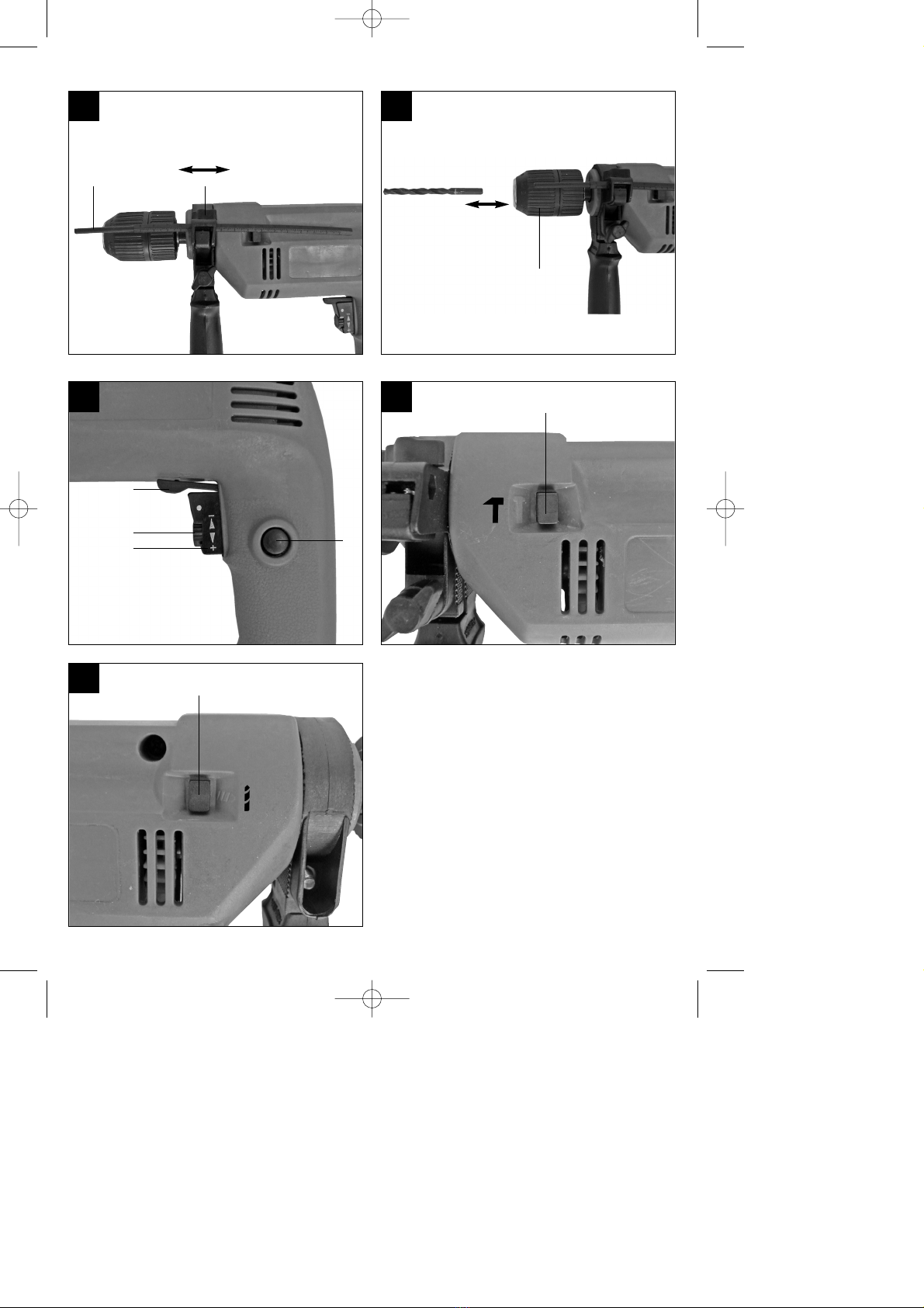
5.1. Fitting the additional handle (Fig. 2-3/Item 8)
The additional handle (8) enables you to achieve
better stability whilst using the hammer drill. Do not
use the tool without the additional handle.
The additional handle (8) is secured to the hammer
drill by a clamp. Turning the lock screw (a) clockwise
tightens this clamp. Turning it anti-clockwise will
release the clamp.
The supplied additional handle must first be fitted
in place. To do this, the clamp must be opened by
turning the locking screw (a) until it is wide
enough for the additional handle to be slid over
the chuck (1) and on to the hammer drill.
After you have mounted the additional handle (8),
swivel it to the most comfortable working position
for yourself.
Now re-tighten the locking screw (a) by turning it
in the opposite direction until the additional
handle is secure.
The additional handle (8) is suitable for both left-
handed and right-handed users.
5.2 Fitting and adjusting the depth stop
(Fig. 4/Item 2)
The depth stop (2) is held in place with the locking
screw (a) on the additional handle (8) by means of a
clamp.
Undo the locking screw (a) and fit the depth stop
(2).
Set the depth stop (2) to the same level as the
drill bit.
Pull the depth stop (2) back by the required
drilling depth.
Retighten the locking screw (a).
Now drill the hole until the depth stop (2) touches
the workpiece.
5.3 Fitting the drill bit (Fig. 5)
Always pull the power plug before making
adjustments to the equipment.
Release the depth stop (2) as described in 5.2
and push it towards the additional handle. This
provides free access to the chuck (1).
This hammer drill is fitted with a keyless chuck
(1).
Open the chuck (1). The drill bit opening (1) must
be large enough to fit the drill bit into.
Select a suitable drill bit. Push the drill bit as far
as possible into the chuck opening.
Close the chuck (1). Check that the drill bit is
secure in the chuck (1).
Check at regular intervals that the drill bit or tool
is secure (pull the mains plug).
6. Operation
6.1 ON/OFF switch (Fig. 6/Item 5)
First fit a suitable drill bit into the tool (see 5.3).
Connect the mains plug to a suitable socket.
Position the drill in the position you wish to drill.
To switch on:
Press the ON/OFF switch (5)
Continuous operation:
Secure the ON/OFF switch (5) with the locking button
(4).
To switch off:
Press the ON/OFF switch (5) briefly.
6.2 Adjusting the speed (Fig. 6/Item 5)
You can infinitely vary the speed whilst using the
tool.
Select the speed by applying a greater or lesser
pressure to the ON/OFF switch (5).
Select the correct speed: The most suitable
speed depends on the workpiece, the type of use
and the drill bit used.
Low pressure on the ON/OFF switch (5): Lower
speed (suitable for: small screws and soft
materials)
Greater pressure on the ON/OFF switch (5):
Higher speed (suitable for large/long screws and
hard materials)
Anleitung_MID_500_E_SPK7:_ 27.01.2010 14:57 Uhr Seite 7

Tip: Start drilling holes at low speed. Then increase
the speed in stages.
Benefits:
The drill bit is easier to control when starting the
hole and will not slide away.
You avoid drilling messy holes (for example in
tiles).
6.3 Preselecting the speed (Fig. 6/Item 6)
The speed setting ring (6) enables you to define
the maximum speed. The ON/OFF switch (5) can
only be pressed to the defined maximum speed
setting.
Set the speed using the setting ring (6) on the
ON/OFF switch (5).
Do not attempt to make this setting whilst the drill
is in use.
6.4 Clockwise/Counter-clockwise switch
(Fig. 6/Item 7)
Change switch position only when the drill is
at a standstill!
Switch the direction of the hammer drill using the
clockwise/counter-clockwise switch (7):
Direction Switch position
Clockwise (forwards and drill) R
Counter-clockwise (reverse) L
6.5 Drill / hammer drill selector switch
(Fig. 7/8)
Change switch position only when the drill is at a
standstill!
Drill
Drill / hammer drill selector switch (3) in the drill
position. (Position A)
Use for: Wood, metal, plastic
Hammer drill
Drill / hammer drill selector switch (3) in the hammer
drill position. (Position B)
Use for: Concrete, rock, masonry
6.6 Tips for working with your hammer drill
6.6.1 Drilling concrete and masonry
Switch the Drill/Hammer drill selector switch (3)
to position B (Hammer drill).
Always use carbide drill bits and a high speed
setting for drilling into masonry and concrete.
6.6.2 Drilling steel
Switch the drill / hammer drill selector switch (3)
to position A (drill).
Always use HSS drill bits (HSS = high speed
steel) and a low speed setting for drilling steel.
We recommend that you lubricate the hole with a
suitable cutting fluid to prevent unnecessary drill
bit wear.
6.6.3 Inserting/Removing screws
Switch the Drill/Hammer drill selector switch (3)
to position A (drill).
Use a low speed setting
6.6.4 Starting holes
If you wish to drill a deep hole in a hard material
(such as steel), we recommend that you start the
hole with a smaller drill bit.
6.6.5 Drilling tiles
To start the hole, switch the drill / hammer drill
selector switch (3) to position A (drill).
Switch the drill / hammer drill selector switch (3)
to position B (hammer drill) as soon as the drill bit
has passed through the tiles.
7. Replacing the power cable
If the power cable for this equipment is damaged, it
must be replaced by the manufacturer or its after-
sales service or similarly trained personnel to avoid
danger.
8. Cleaning, maintenance and
ordering of spare parts
Always pull out the mains power plug before starting
any cleaning work.
8.1 Cleaning
Keep all safety devices, air vents and the motor
housing free of dirt and dust as far as possible.
Wipe the equipment with a clean cloth or blow it
with compressed air at low pressure.
We recommend that you clean the device
immediately each time you have finished using it.
Clean the equipment regularly with a moist cloth
and some soft soap. Do not use cleaning agents
or solvents; these could attack the plastic parts of
the equipment. Ensure that no water can seep
into the device.
GB
8
Anleitung_MID_500_E_SPK7:_ 27.01.2010 14:57 Uhr Seite 8

GB
9
8.2 Carbon brushes
In case of excessive sparking, have the carbon
brushes checked only by a qualified electrician.
Important! The carbon brushes should not be rep
laced by anyone but a qualified electrician.
8.3 Maintenance
There are no parts inside the equipment which
require additional maintenance.
8.4 Ordering replacement parts:
Please quote the following data when ordering
replacement parts:
Type of machine
Article number of the machine
Identification number of the machine
Replacement part number of the part required
For our latest prices and information please go to
www.isc-gmbh.info
9. Disposal and recycling
The unit is supplied in packaging to prevent its being
damaged in transit. This packaging is raw material
and can therefore be reused or can be returned to
the raw material system.
The unit and its accessories are made of various
types of material, such as metal and plastic.
Defective components must be disposed of as
special waste. Ask your dealer or your local council.
Anleitung_MID_500_E_SPK7:_ 27.01.2010 14:57 Uhr Seite 9

10
GB
tGUARANTEE CERTIFICATE
Dear Customer,
In the unlikely event that your device develops a fault, we are truly sorry for this, and suggest that you please
contact our service department at the address shown on this guarantee card, or contact the nearest authorised
DIY store. Please note the following terms, under which guarantee claims can be made:
1. These guarantee terms cover additional guarantee rights and do not affect your statutory warranty rights.
We do not charge you for this guarantee.
2. Our guarantee only covers problems caused by material or manufacturing defects, and it is restricted to the
rectification of these defects or replacement of the device. Please note that our devices have not been
designed for use in commercial, trade or industrial applications. Consequently, the guarantee is invalidated
if the equipment is used in commercial, trade or industrial applications or for other equivalent activities. The
following are also excluded from our guarantee: compensation for transport damage, damage caused by
failure to comply with the installation/assembly instructions or damage caused by unprofessional
installation, failure to comply with the operating instructions (e.g. connection to the wrong mains voltage or
current type), misuse or inappropriate use (such as overloading of the device or use of non-approved tools
or accessories), failure to comply with the maintenance and safety regulations, ingress of foreign bodies
into the device (e.g. sand, stones or dust), effects of force or external influences (e.g. damage caused by
the device being dropped) and normal wear resulting from proper operation of the device. This applies in
particular to rechargeable batteries for which we nevertheless issue a guarantee period of 12 months.
The guarantee is rendered null and void if any attempt is made to tamper with the device.
3. The guarantee is valid for a period of 2 years starting from the purchase date of the device. Guarantee
claims should be submitted before the end of the guarantee period within two weeks of the defect being
noticed. No guarantee claims will be accepted after the end of the guarantee period. The original guarantee
period remains applicable to the device even if repairs are carried out or parts are replaced. In such cases,
the work performed or parts fitted will not result in an extension of the guarantee period, and no new
guarantee will become active for the work performed or parts fitted. This also applies when an on-site
service is used.
4. In order to assert your guarantee claim, please send your defective device postage-free to the address
shown below, or contact the nearest authorised DIY store. Please enclose either the original or a copy of
your sales receipt or another dated proof of purchase. Please keep your sales receipt in a safe place, as it is
your proof of purchase. It would help us if you could describe the nature of the problem in as much detail as
possible. If the defect is covered by our guarantee then your device will either be repaired immediately and
returned to you, or we will send you a new device.
Anleitung_MID_500_E_SPK7:_ 27.01.2010 14:57 Uhr Seite 10

D
11
“WARNUNG - Zur Verringerung des Verletzungsrisikos Bedienungsanleitung lesen”
Tragen Sie einen Gehörschutz.
Die Einwirkung von Lärm kann Gehörverlust bewirken.
Tragen Sie eine Staubschutzmaske.
Beim Bearbeiten von Holz und anderer Materialien kann gesundheitsschädlicher Staub
entstehen. Asbesthaltiges Material darf nicht bearbeitet werden!
Tragen Sie eine Schutzbrille.
Während der Arbeit entstehende Funken oder aus dem Gerät heraustretende Splitter, Späne
und Stäube können Sichtverlust bewirken.
Anleitung_MID_500_E_SPK7:_ 27.01.2010 14:57 Uhr Seite 11

12
D
Achtung!
Beim Benutzen von Geräten müssen einige
Sicherheitsvorkehrungen eingehalten werden, um
Verletzungen und Schäden zu verhindern. Lesen Sie
diese Bedienungsanleitung / Sicherheitshinweise
deshalb sorgfältig durch. Bewahren Sie diese gut
auf, damit Ihnen die Informationen jederzeit zur
Verfügung stehen. Falls Sie das Gerät an andere
Personen übergeben sollten, händigen Sie diese
Bedienungsanleitung / Sicherheitshinweise bitte mit
aus. Wir übernehmen keine Haftung für Unfälle oder
Schäden, die durch Nichtbeachten dieser Anleitung
und den Sicherheitshinweisen entstehen.
1. Sicherheitshinweise
Die entsprechenden Sicherheitshinweise finden Sie
im beiliegenden Heftchen!
WARNUNG
Lesen Sie alle Sicherheitshinweise und
Anweisungen. Versäumnisse bei der Einhaltung der
Sicherheitshinweise und Anweisungen können
elektrischen Schlag, Brand und/oder schwere
Verletzungen verursachen zur Folge haben.
Bewahren Sie alle Sicherheitshinweise und
Anweisungen für die Zukunft auf.
2. Gerätebeschreibung (Bild 1)
1. Bohrfutter
2. Bohrtiefenanschlag
3. Bohren-/Schlagbohren-Umschalter
4. Feststellknopf
5. Ein-/Ausschalter
6. Drehzahl-Einstellring
7. Rechts-/Linkslauf-Umschalter
8. Zusatzhandgriff
3. Bestimmungsgemäße Verwendung
Die Bohrmaschine ist zum Bohren von Löchern in
Holz, Eisen, Buntmetallen und Gestein unter
Verwendung des entsprechenden Bohrwerkzeugs
ausgelegt.
Die Maschine darf nur nach ihrer Bestimmung
verwendet werden. Jede weitere darüber
hinausgehende Verwendung ist nicht
bestimmungsgemäß. Für daraus hervorgerufene
Schäden oder Verletzungen aller Art haftet der
Benutzer/Bediener und nicht der Hersteller.
Bitte beachten Sie, dass unsere Geräte
bestimmungsgemäß nicht für den gewerblichen,
handwerklichen oder industriellen Einsatz konstruiert
wurden. Wir übernehmen keine Gewährleistung,
wenn das Gerät in Gewerbe-, Handwerks- oder
Industriebetrieben sowie bei gleichzusetzenden
Tätigkeiten eingesetzt wird.
4. Technische Daten
Netzspannung: 230 V ~ 50 Hz
Leistungsaufnahme: 500 W
Leerlauf-Drehzahl: 0-3000 min-1
Bohrleistung: Beton 13 mm
Stahl 10 mm
Holz 20 mm
Schutzklasse: II / 쓑
Gewicht: 1,7 kg
Geräusch und Vibration
Die Geräusch- und Vibrationswerte wurden entspre-
chend EN 60745 ermittelt.
Schalldruckpegel LpA 92 dB(A)
Unsicherheit KpA 3 dB
Schallleistungspegel LWA 106 dB(A)
Unsicherheit KWA 3 dB
Tragen Sie einen Gehörschutz.
Die Einwirkung von Lärm kann Gehörverlust bewir-
ken.
Schwingungsgesamtwerte (Vektorsumme dreier
Richtungen) ermittelt entsprechend EN 60745.
Schlagbohren in Beton
Schwingungsemissionswert ah= 13,219 m/s2
Unsicherheit K = 4,125 m/s2
Bohren in Metall
Schwingungsemissionswert ah= 5,036 m/s2
Unsicherheit K = 2,103 m/s2
Achtung!
Der Schwingungswert wird sich aufgrund des Ein-
satzbereiches des Elektrowerkzeuges ändern und
kann in Ausnahmefällen über dem angegebenen
Wert liegen.
Anleitung_MID_500_E_SPK7:_ 27.01.2010 14:57 Uhr Seite 12

13
D
Beschränken Sie die Geräuschentwicklung und
Vibration auf ein Minimum!
Verwenden Sie nur einwandfreie Geräte.
Warten und reinigen Sie das Gerät regelmäßig.
Passen Sie Ihre Arbeitsweise dem Gerät an.
Überlasten Sie das Gerät nicht.
Lassen Sie das Gerät gegebenenfalls
überprüfen.
Schalten Sie das Gerät aus, wenn es nicht
benutzt wird.
Tragen Sie Handschuhe.
5. Vor Inbetriebnahme
Überzeugen Sie sich vor dem Anschließen, dass die
Daten auf dem Typenschild mit den Netzdaten
übereinstimmen.
Ziehen Sie immer den Netzstecker, bevor Sie
Einstellungen am Gerät vornehmen.
5.1. Zusatzhandgriff montieren (Bild 2-3/Pos. 8)
Der Zusatzhandgriff (8) bietet Ihnen während der
Benutzung der Schlagbohrmaschine zusätzlichen
Halt. Benutzen Sie das Gerät daher nicht ohne den
Zusatzhandgriff.
Befestigt wird der Zusatzhandgriff (8) an der
Schlagbohrmaschine durch Klemmung. Durch
Drehen der Feststellschraube (a) im Uhrzeigersinn
wird die Klemmung angezogen. Drehen gegen den
Uhrzeigersinn löst die Klemmung.
Der beiliegende Zusatzhandgriff muss zunächst
montiert werden. Hierzu ist durch Drehen der
Feststellschraube (a) die Klemmung weit genug
zu öffnen, damit der Zusatzhandgriff über das
Bohrfutter (1) auf die Schlagbohrmaschine
geschoben werden kann.
Nach dem Aufschieben des Zusatzhandgriffes
(8), schwenken Sie diesen in die für Sie
angenehmste Arbeitsposition.
Jetzt die Feststellschraube (a) in entgegen
gesetzter Drehrichtung wieder festdrehen, bis der
Zusatzhandgriff fest sitzt.
Der Zusatzhandgriff (8) ist für Rechtshänder
ebenso wie für Linkshänder geeignet.
5.2 Tiefenanschlag montieren und einstellen
(Bild 4/Pos. 2)
Der Tiefenanschlag (2) wird mit der
Feststellschraube (a) am Zusatzhandgriff (8) durch
Klemmung gehalten.
Lösen Sie die Feststellschraube (a) und setzen
Sie den Tiefenanschlag (2) ein .
Bringen Sie den Tiefenanschlag (2) auf gleiche
Ebene zum Bohrer.
Ziehen Sie den Tiefenanschlag (2) um die
gewünschte Bohrtiefe zurück.
Ziehen Sie die Feststelllschraube (a) wieder fest.
Bohren Sie nun das Loch, bis der
Tiefenanschlag (2) das Werkstück berührt.
5.3 Einsetzen des Bohrers (Bild 5)
Ziehen Sie immer den Netzstecker, bevor Sie
Einstellungen am Gerät vornehmen.
Tiefenanschlag (2) wie in 5.2 beschrieben lösen
und in Richtung Bohrergriff schieben. Somit hat
man freien Zugang zum Bohrfutter (1).
Diese Schlagbohrmaschine ist mit einem
Schnellspann-Bohrfutter (1) ausgestattet.
Drehen Sie das Bohrfutter (1) auf. Die
Bohreröffnung muss groß genug sein, um den
Bohrer aufzunehmen.
Wählen Sie einen geeigneten Bohrer aus.
Schieben Sie das Werkzeug soweit wie möglich
in die Bohrfutteröffnung hinein.
Drehen Sie das Bohrfutter (1) zu. Prüfen Sie, ob
der Bohrer fest im Bohrfutter (1) sitzt.
Überprüfen Sie in regelmäßigen Abständen den
festen Sitzt des Bohrers bzw. Werkzeuges
(Netzstecker ziehen!).
6. Bedienung
6.1 Ein/Ausschalter (Bild 6/Pos. 5)
Setzen Sie zuerst einen geeigneten Bohrer in
das Gerät ein (siehe 5.3).
Verbinden Sie den Netzstecker mit einer
geeigneten Steckdose.
Setzen Sie die Bohrmaschine direkt an der
Bohrstelle an.
Einschalten:
Ein-/Ausschalter (5) drücken
Dauerbetrieb:
Ein-/Ausschalter (5) mit Feststellknopf (4) sichern.
Ausschalten:
Ein-/Ausschalter (5) kurz eindrücken.
6.2 Drehzahl einstellen (Bild 6/Pos. 5)
Sie können die Drehzahl während des Betriebes
stufenlos steuern.
Durch mehr oder wenig starkes Drücken des
Ein-/Ausschalters (5) wählen Sie die Drehzahl.
Wahl der richtigen Drehzahl: Die am besten
geeignete Drehzahl ist abhängig vom Werkstück,
von der Betriebsart und vom eingesetzten
Bohrer.
Geringer Druck auf Ein-/Ausschalter (5):
Anleitung_MID_500_E_SPK7:_ 27.01.2010 14:57 Uhr Seite 13

niedrigere Drehzahl (Geeignet für: kleine
Schrauben, weiche Werkstoffe)
Größerer Druck auf Ein-/Ausschalter (5): höhere
Drehzahl (Geeignet für: große/lange Schrauben,
harte Werkstoffe)
Tipp: Bohren Sie Bohrlöcher mit geringer Drehzahl
an. Erhöhen Sie Die Drehzahl danach schrittweise.
Vorteile:
Der Bohrer ist beim Anbohren leichter zu
kontrollieren und rutscht nicht ab.
Sie vermeiden zersplitterte Bohrlöcher (z.B. bei
Kacheln).
6.3 Vorwählen der Drehzahl (Bild 6/Pos. 6)
Der Drehzahl-Einstellring (6) ermöglicht es
Ihnen, die maximale Drehzahl zu definieren. Der
Ein-/Ausschalter (5) kann nur noch bis zur
vorgegebenen Maximaldrehzahl eingedrückt
werden.
Stellen Sie die Drehzahl mit dem Einstellring (6)
im Ein-/Ausschalter (5) ein.
Nehmen Sie diese Einstellung nicht während des
Bohrens vor.
6.4 Rechts-/Linkslauf-Umschalter (Bild 6/Pos. 7)
Nur im Stillstand umschalten!
Stellen Sie mit dem Rechts-/Linkslauf-
Umschalter (7) die Laufrichtung des
Schlagbohrers ein:
Laufrichtung Schalterposition
Rechtslauf (Vorwärts und Bohren) R
Linkslauf (Rücklauf) L
6.5 Bohren/Schlagbohren-Umschalter
(Bild 7/8)
Nur im Stillstand umschalten!
Bohren:
Bohren-/Schlagbohren-Umschalter (3) in Stellung
Bohren. (Position A)
Anwendung: Hölzer; Metalle; Kunststoffe
Schlagbohren:
Bohren-/Schlagbohren-Umschalter (3) in Stellung
Schlagbohren. (Position B)
Anwendung: Beton; Gestein; Mauerwerk
6.6 Tipps für das Arbeiten mit Ihrer
Schlagbohrmaschine
6.6.1 Bohren von Beton und Mauerwerk
Stellen Sie den Bohren/Schlagbohren
Umschalter (3) auf die Position B
(Schlagbohren).
Benutzen Sie für das Bearbeiten von Mauerwerk
oder Beton immer Hartmetallbohrer und eine
hohe Drehzahleinstellung.
6.6.2 Bohren von Stahl
Stellen Sie den Bohren/Schlagbohren
Umschalter (3) auf die Position A (Bohren).
Benutzen Sie für das Bearbeiten von Stahl
immer HSS-Bohrer (HSS = Hochlegierter
Schnellarbeitsstahl) und eine niedrige
Drehzahleinstellung.
Es ist empfehlenswert die Bohrung durch ein
geeignetes Kühlmittel zu schmieren um
unnötigen Bohrerverschleiß zu vermeiden.
6.6.3 Schrauben eindrehen/lösen
Stellen Sie den Bohren/Schlagbohren
Umschalter (3) auf die Position A (Bohren).
Benutzen Sie eine niedrige Drehzahleinstellung.
6.6.4 Löcher anbohren
Falls Sie ein tiefes Loch in ein hartes Material (wie
etwa Stahl) bohren möchten, empfehlen wir, dass
Sie das Loch mit einem kleineren Bohrer vorbohren.
6.6.5 Bohren in Fliesen und Kacheln
Stellen Sie zum Anbohren den Umschalter
Bohren/Schlagbohren (3) auf die Position A
(Bohren).
Stellen Sie den Umschalter
Bohren/Schlagbohren (3) auf die Position B
(Schlagbohren), sobald der Bohrer die
Fliese/Kachel durchschlagen hat.
7. Austausch der
Netzanschlussleitung
Wenn die Netzanschlussleitung dieses Gerätes
beschädigt wird, muss sie durch den Hersteller oder
seinen Kundendienst oder eine ähnlich qualifizierte
Person ersetzt werden, um Gefährdungen zu
vermeiden.
14
D
Anleitung_MID_500_E_SPK7:_ 27.01.2010 14:57 Uhr Seite 14

8. Reinigung, Wartung und
Ersatzteilbestellung
Ziehen Sie vor allen Reinigungsarbeiten den
Netzstecker.
8.1 Reinigung
Halten Sie Schutzvorrichtungen, Luftschlitze und
Motorengehäuse so staub- und schmutzfrei wie
möglich. Reiben Sie das Gerät mit einem
sauberen Tuch ab oder blasen Sie es mit
Druckluft bei niedrigem Druck aus.
Wir empfehlen, dass Sie das Gerät direkt nach
jeder Benutzung reinigen.
Reinigen Sie das Gerät regelmäßig mit einem
feuchten Tuch und etwas Schmierseife.
Verwenden Sie keine Reinigungs- oder
Lösungsmittel; diese könnten die Kunststoffteile
des Gerätes angreifen. Achten Sie darauf, dass
kein Wasser in das Geräteinnere gelangen kann.
8.2 Kohlebürsten
Bei übermäßiger Funkenbildung lassen Sie die
Kohlebürsten durch eine Elektrofachkraft überprüfen.
Achtung! Die Kohlebürsten dürfen nur von einer
Elektrofachkraft ausgewechselt werden.
8.3 Wartung
Im Geräteinneren befinden sich keine weiteren zu
wartenden Teile.
8.4 Ersatzteilbestellung:
Bei der Ersatzteilbestellung sollten folgende
Angaben gemacht werden;
Typ des Gerätes
Artikelnummer des Gerätes
Ident-Nummer des Gerätes
Ersatzteilnummer des erforderlichen Ersatzteils
Aktuelle Preise und Infos finden Sie unter
www.isc-gmbh.info
9. Entsorgung und Wiederverwertung
Das Gerät befindet sich in einer Verpackung um
Transportschäden zu verhindern. Diese Verpackung
ist Rohstoff und ist somit wieder verwendbar oder
kann dem Rohstoffkreislauf zurückgeführt werden.
Das Gerät und dessen Zubehör bestehen aus
verschiedenen Materialien, wie z.B. Metall und
Kunststoffe. Führen Sie defekte Bauteile der
Sondermüllentsorgung zu. Fragen Sie im
Fachgeschäft oder in der Gemeindeverwaltung nach!
15
D
Anleitung_MID_500_E_SPK7:_ 27.01.2010 14:57 Uhr Seite 15

16
D
kGARANTIEURKUNDE
Sehr geehrte Kundin, sehr geehrter Kunde,
unsere Produkte unterliegen einer strengen Qualitätskontrolle. Sollte dieses Gerät dennoch einmal nicht ein-
wandfrei funktionieren, bedauern wir dies sehr und bitten Sie, sich an unseren Servicedienst unter der auf die-
ser Garantiekarte angegebenen Adresse, oder an den nächstgelegenen zuständigen Baumarkt zu wenden.
Für die Geltendmachung von Garantieansprüchen gilt Folgendes:
1. Diese Garantiebedingungen regeln zusätzliche Garantieleistungen. Ihre gesetzlichen Gewährleistungsan-
sprüche werden von dieser Garantie nicht berührt. Unsere Garantieleistung ist für Sie kostenlos.
2. Die Garantieleistung erstreckt sich ausschließlich auf Mängel, die auf Material- oder Herstellungsfehler zu-
rückzuführen sind und ist auf die Behebung dieser Mängel bzw. den Austausch des Gerätes beschränkt.
Bitte beachten Sie, dass unsere Geräte bestimmungsgemäß nicht für den gewerblichen, handwerklichen
oder industriellen Einsatz konstruiert wurden. Ein Garantievertrag kommt daher nicht zustande, wenn das
Gerät in Gewerbe-, Handwerks- oder Industriebetrieben sowie bei gleichzusetzenden Tätigkeiten einge-
setzt wird.
Von unserer Garantie sind ferner Ersatzleistungen für Transportschäden, Schäden durch Nichtbeachtung
der Montageanleitung oder aufgrund nicht fachgerechter Installation, Nichtbeachtung der Gebrauchsanlei-
tung (wie durch z.B. Anschluss an eine falsche Netzspannung oder Stromart), missbräuchliche oder un-
sachgemäße Anwendungen (wie z.B. Überlastung des Gerätes oder Verwendung von nicht zugelassenen
Einsatzwerkzeugen oder Zubehör), Nichtbeachtung der Wartungs- und Sicherheitsbestimmungen, Ein-
dringen von Fremdkörpern in das Gerät (wie z.B. Sand, Steine oder Staub), Gewaltanwendung oder
Fremdeinwirkungen (wie z. B. Schäden durch Herunterfallen) sowie durch verwendungsgemäßen, üblichen
Verschleiß ausgeschlossen. Dies gilt insbesondere für Akkus, auf die wir dennoch eine Garantiezeit von
12 Monaten gewähren.
Der Garantieanspruch erlischt, wenn an dem Gerät bereits Eingriffe vorgenommen wurden.
3. Die Garantiezeit beträgt 2 Jahre und beginnt mit dem Kaufdatum des Gerätes. Garantieansprüche sind vor
Ablauf der Garantiezeit innerhalb von zwei Wochen, nachdem Sie den Defekt erkannt haben, geltend zu
machen. Die Geltendmachung von Garantieansprüchen nach Ablauf der Garantiezeit ist ausgeschlossen.
Die Reparatur oder der Austausch des Gerätes führt weder zu einer Verlängerung der Garantiezeit noch
wird eine neue Garantiezeit durch diese Leistung für das Gerät oder für etwaige eingebaute Ersatzteile in
Gang gesetzt. Dies gilt auch bei Einsatz eines Vor-Ort-Services.
4. Für die Geltendmachung Ihres Garantieanspruches übersenden Sie bitte das defekte Gerät portofrei an die
unten angegebene Adresse, oder wenden Sie sich bitte an den nächstgelgenen zuständigen Baumarkt.
Fügen Sie den Verkaufsbeleg im Original oder einen sonstigen datierten Kaufnachweis bei. Bitte bewahren
Sie deshalb den Kassenbon als Nachweis gut auf! Beschreiben Sie uns bitte den Reklamationsgrund
möglichst genau. Ist der Defekt des Gerätes von unserer Garantieleistung erfasst, erhalten Sie umgehend
ein repariertes oder neues Gerät zurück.
iSC GmbH • Eschenstraße 6 • 94405 Landau/Isar (Deutschland)
Anleitung_MID_500_E_SPK7:_ 27.01.2010 14:57 Uhr Seite 16

17
RO
“Avertisment – Citiţi manualul de utilizare pentru a reduce riscul producerii unui accident”
Purtaøi o protecøie a auzului.
Acøiunea zgomotului pot duce la diminuarea auzului.
Purtaøi o mascå de protecøie contra prafului.
La prelucrarea lemnului μi a altor materiale poate rezulta praf periculos pentru sånåtate. Nu se
vor prelucra materiale cu conøinut de azbest!
Purtaøi ochelari de protecøie.
Scânteile rezultate pe timpul lucrului sau talaμul, aμchiile μi praful care iese din aparat pot duce
la diminuarea vederi.
Anleitung_MID_500_E_SPK7:_ 27.01.2010 14:57 Uhr Seite 17

18
RO
Atenţie!
La utilizarea aparatelor trebuie respectate câteva
măsuri de siguranţă, pentru a evita accidentele şi
daunele. De aceea, citiţi cu grijă instrucţiunile de
utilizare/indicaţiile de siguranţă. Păstraţi aceste
materiale în bune condiţii, pentru ca aceste informaţii
să fie disponibile în orice moment. Dacă predaţi
aparatul altor persoane, înmânaţi-le şi aceste
instrucţiuni de utilizare /indicaţii de siguranţă. Nu ne
asumăm nici o răspundere pentru accidente sau
daune care rezultă din nerespectarea acestor
instrucţiuni de utilizare şi a indicaţiilor de siguranţă.
1. Indicaøii de siguranøå
Indicaøiile de siguranøå aferente le gåsiøi în broμura
anexatå.
AVERTIZARE!
Citiţi indicaţiile de siguranţă şi îndrumările.
Nerespectarea indicaţiilor de siguranţă şi a
îndrumărilor poate avea ca urmare electrocutare,
incendiu şi/sau răniri grave.
Păstraţi pentru viitor toate indicaţiile de
siguranţă şi îndrumările.
2. Descrierea aparatului (vezi Figura 1)
1. Mandrină
2. Opritor adâncime de găurire
3. Comutator găurire / percuţie
4. Buton de fixare
5. Întrerupător pornire/oprire
6. Reglor al turaţiei
7. Comutator rotire stânga/dreapta
8. Mâner suplimentar
3. Utilizarea conform scopului
Maşina de găurit este construită pentru găurirea
lemnului, fierului, a metalelor neferoase şi a pietrei cu
utilizarea sculelor de găurit corespunzătoare.
Maşina se va utiliza numai conform scopului pentru
care este concepută. Orice altă utilizare nu este în
conformitate cu scopul. Pentru pagubele sau
vătămările rezultate în acest caz este responsabil
utilizatorul/operatorul şi nu producătorul.
Vă rugăm să ţineţi cont de faptul că maşinile noastre
nu sunt construite pentru utilizare în domeniile
meşteşugăreşti şi industriale. Noi nu preluăm nici o
garanţie atunci când aparatul este folosit în
întreprinderile meşteşugăreşti sau industriale ori în
scopuri similare.
4. Date tehnice
Tensiunea de reţea: 230 V~ 50 Hz
Puterea consumată: 500 W
Turaţie la mers în gol: 0-3000 min-1
Capacitatea de găurire: Beton 13 mm
Oţel 10 mm
Lemn 20 mm
Clasa de protecţie: II/쓑
Greutate: 1,7 kg
Zgomote şi vibraţii
Valorile nivelelor de zgomot şi de vibraţie au fost
calculate conform EN 60745.
Nivelul presiunii sonore LpA 92 dB (A)
Nesiguranţă KpA 3 dB
Nivelul capacităţii sonore LWA 106 dB (A)
Nesiguranţă KWA 3 dB
Purtaţi protecţie antifonică.
Expunerea la zgomot poate cauza deteriorarea sau
pierderea auzului.
Valorile totale ale nivelului de vibraţii (suma vectorială
a trei direcţii), calculate conform EN 60745.
Găurire prin percuţie în beton
Valoare a vibraţiilor emise ah= 13,219 m/s2
Nesiguranţă K = 4,125 m/s2
Găurire în metal
Valoare a vibraţiilor emise ah= 5,036 m/s2
Nesiguranţă K = 2,103 m/s2
Atenţie!
Valoarea nivelului de vibraţii se schimbă în funcţie de
locul utilizării sculei electrice, putându-se situa în
cazuri excepţionale peste valoarea indicată mai sus.
Anleitung_MID_500_E_SPK7:_ 27.01.2010 14:57 Uhr Seite 18

19
RO
Limitaţi zgomotul şi vibraţiile la un nivel minim.
Utilizaţi numai aparate în stare ireproşabilă.
Întreţineţi şi curăţaţi aparatul cu regularitate.
Adaptaţi modul dvs. de lucru aparatului.
Nu suprasolicitaţi aparatul.
Dacă este necesar, lăsaţi aparatul să fie verificat.
Decuplaţi aparatul, atunci când acesta nu este
utilizat.
Purtaţi mănuşi!
5. Înainte de punerea în funcţiune
Asiguraţi-vă înainte de racordare că datele de pe
plăcuţa de identificare corespund datelor din reţea.
Scoateţi întotdeauna ştecherul din priză înainte de a
executa reglaje la maşină.
5.1.Montarea mânerului suplimentar
(Fig. 2-3/Poz. 8)
Mânerul suplimentar (8) vă oferă stabilitate
suplimentară în timpul utilizării maşinii de găurit cu
percuţie. Din acest motiv nu folosiţi maşina fără
mânerul suplimentar.
Fixarea mânerului suplimentar (8) la maşină se face
cu ajutorul colierului de fixare. Prin rotirea şurubului
de fixare (a) în sens orar se strânge colierului de
fixare. Prin rotirea în sens antiorar se desface fixarea
mânerului.
Mânerul suplimentar anexat trebuie mai întâi
montat. Pentru aceasta trebuie ca prin rotirea
şurubului de fixare să deschideţi colierul suficient
de mult, pentru ca mânerul suplimentar să poată
fi împins peste mandrină (1) pe maşina de găurit
prin percuţie.
După poziţionarea mânerului suplimentar (8)
potriviţi-l în poziţia de lucru cea mai comodă
pentru Dvs..
Acum strângeţi din nou şurubul de fixare (a) prin
rotire în sens invers, până când mânerul
suplimentar este bine fixat.
Mânerul suplimentar (8) este indicat atât pentru
dreptaci cât şi pentru stângaci.
5.2 Montarea şi reglarea opritorului adâncimii de
găurire (Fig. 4/Poz. 2)
Opritorul în adâncime (2) este fixat pe mânerul
suplimentar (8) cu ajutorul şurubului de fixare (a).
Desfacaţi şurubul de fixare (a) şi poziţionaţi
opritorul în adâncime (2).
Aduceţi opritorul adâncimii de găurire (2) la
acelaşi nivel cu burghiul.
Trageţi opritorul în adâncime (2) cu exact
adâncimea de găurire dorită înapoi.
Strângeţi din nou şurubul de fixare (a).
Daţi acum gaura şi înaintaţi până când opritorul
adâncimii de găurire (2) atinge piesa prelucrată.
5.3 Montarea burghiului (Fig 5)
Scoateţi întotdeauna ştecherul din priză înainte
de a efectua reglaje ale aparatului.
Desfaceţi opritorul adâncimii de găurire conform
descrierii de la punctul 5.2 şi împingeţi-l în
direcţia mânerului. Aveţi acum acces liber la
mandrină (1).
Această maşină de găurit prin percuţie este
dotată cu o mandrină cu prindere rapidă (1).
Rotiţi mandrina (1) deschizând-o. Deschiderea
trebuie să fie suficient de mare pentru a putea
prelua burghiul.
Alegeţi un burghiu adecvat. Împingeţi burghiul la
maxim în deschiderea mandrinei.
Rotiţi mandrina (1) închizând-o. Verificaţi dacă
burghiul este bine fixat în mandrină (1).
Verificaţi la intervale regulate de timp dacă
burghiul, respectiv scula sunt bine prinse în
mandrină (decuplaţi ştecherul de la reţea!).
6. Operare
6.1 Întrerupător pornire/oprire (Fig. 6/Poz. 5)
Montaţi mai întâi un burghiu potrivit în maşină
(vezi 5.3).
Racordaţi cablul de reţea la o priză adecvată.
Aşezaţi maşina de găurit pe punctul unde
urmează să se dea gaura.
Pornire:
Apăsaţi întrerupătorul pornire/oprire (5)
Funcţionarea de durată:
Asiguraţi întrerupătorul pornire/oprire (5) cu butonul
de fixare (4).
Atenţie! Un blocaj este posibil doar în cazul rotaţiei
spre dreapta.
Oprire:
Apăsaţi scurt întrerupătorul pornire/oprire (5).
6.2 Reglarea turaţiei (Fig. 6/Poz. 5)
În timpul utilizării maşinii de găurit puteţi regla
turaţia acesteia fără trepte.
Prin apăsarea mai tare sau mai uşoară a
întrerupătorului pornire/oprire (5) alegeţi turaţia.
Alegerea turaţiei corecte: Turaţia adecvată
depinde de piesa de prelucrat, de regimul de
funcţionare şi de burghiul folosit.
Apăsare uşoară pe întrerupătorul pornire/oprire
(5): turaţie joasă (adecvată pentru: şuruburi mici,
materiale de prelucrat moi)
Anleitung_MID_500_E_SPK7:_ 27.01.2010 14:57 Uhr Seite 19

RO
20
Apăsare mai tare pe întrerupătorul pornire/oprire
(5): turaţie mai mare (adecvată pentru: şuruburi
mari/lungi, materiale dure)
Pont: Folosiţi o turaţie mai mică atunci când începeţi
să daţi gaura. Creşteţi apoi treptat turaţia.
Avantaje:
Când începeţi să daţi gaura, burghiul este mai
uşor de controlat şi nu alunecă.
Evitaţi astfel găurile aşchiate (de ex. la plăcile de
teracotă).
6.3 Preselecţia turaţiei (Fig. 6/Poz. 6)
Inelul de reglare a turaţiei (6) vă permite definirea
turaţiei maxime. Întrerupătorul de pornire/oprire
(5) nu mai poate fi apăsat decât până la turaţia
maximă prestabilită.
Alegeţi turaţia maximă cu ajutorul inelului de
reglare a turaţiei (6) aflat în dreptul
întrerupătorului de pornire/oprire (5).
Nu efectuaţi acest reglaj în timpul procesului de
găurire.
6.4 Comutatorul rotire stânga/dreapta
(Fig. 6/Poz. 7)
Comutarea se va realiza numai când aparatul
este în repaus!
Alegeţi sensul de lucru al maşinii de găurit prin
percuţie cu ajutorul comutatorului rotire spre
stânga/rotire spre dreapta (7):
Sensul de lucru al maşinii Poziţia comutatorului
Rotaţie spre dreapta (înainte şi găurire) R
Rotaţie spre stânga (înapoi) L
6.5 Comutator găurire/percuţie (Fig. 7/8)
Comutarea se va realiza numai când aparatul
este în repaus!
Găurire:
Comutatorul găurire/percuţie (3) este în poziţia
găurire. (Poziţia A)
Utilizare: lemn; metale; materiale plastice
Găurire prin percuţie:
Comutatorul găurire/percuţie (3) este în poziţia
percuţie. (Poziţia B)
Utilizare: beton; piatră; zidărie
6.6 Ponturi pentru lucrul cu maşina de găurit cu
percuţie
6.6.1 Găurire în beton şi zidărie
Poziţionaţi comutatorul găurire/percuţie (3) în
poziţia B (găurire prin percuţie).
În cazul zidăriei sau al betonului utilizaţi
întotdeauna burghie pentru metale dure şi o
turaţie ridicată.
6.6.2 Găurire în oţel
Poziţionaţi comutatorul găurire/percuţie (3) în
poziţia A (găurire).
În cazul oţelului utilizaţi întotdeauna burghie HSS
(HSS = oţel rapid, înalt aliat) şi o turaţie joasă.
Este recomandată ungerea găurii cu un agent de
răcire adecvat, pentru a evita uzura inutilă a
maşinii de găurit şi a burghiului.
6.6.3 Strângerea/Desfacerea şuruburilor
Poziţionaţi comutatorul găurire/percuţie (3) în
poziţia A (găurire).
Folosiţi o turaţie joasă.
6.6.4 Găuri pregătitoare
În cazul în care doriţi să daţi o gaură adâncă într-un
material dur (cum ar fi oţelul), vă recomandăm să daţi
mai întâi o gaură pregătitoare cu un burghiu mai mic
în punctul respectiv.
6.6.5 Găurire în faianţă, gresie şi plăci de
teracotă
Aduceţi comutatorul de găurire/percuţie (3) în
poziţia A (găurire) pentru a da gaura pregătitoare.
Aduceţi comutatorul de găurire/percuţie (3) în
poziţia B (găurire prin percuţie) imediat ce
burghiul a străpuns gresia/faianţa/placa de
teracotă.
7. Schimbarea cablului de racord la
reţea
În cazul deteriorării cablului de racord la reţea a
acestui aparat, pentru a evita pericolele acesta
trebuie înlocuit de către producător sau un scervice
clienţi sau de opersoană cu calificare similară.
Anleitung_MID_500_E_SPK7:_ 27.01.2010 14:57 Uhr Seite 20
This manual suits for next models
1
Table of contents
Languages:
Other Maestro Drill manuals