Maestro MID 1000 E User manual

Original operating instructions
Hammer Drill
Originalbetriebsanleitung
Schlagbohrmaschine
Instrucţiuni de utilizare originale
Maşină de găurit cu percuţie
Orijinal Kullanma Talimatı
Darbeli Matkap
Art.-No.: 42.598.13 I.-Nr.: 11010 MID 1000 E


2

4

5
GB

6
GB

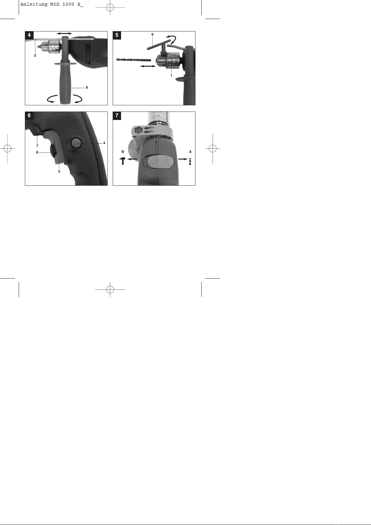
Additional information for electric power tools ŸThe supplied additional handle (8) must first be
mWarning! fitted. To do this, the clamp must be opened by
The specified vibration value was established in turning the handle until it is wide enough for the
accordance with a standardized testing method. It additional handle to be slid over the chuck (1) and
may change according to how the electric equipment on to the hammer drill.
is used and may exceed the specified value in ŸAfter you have positioned the additional handle (8),
exceptional circumstances. turn it to the most comfortable working position for
you.
The specified vibration value can be used to compare ŸNow turn the handle in the opposite direction again
the equipment with other electric power tools. until the additional handle is secure.
ŸThe additional handle (8) is suitable for both
The specified vibration value can be used for initial lefthanded and right-handed users.
assessment of a harmful effect.
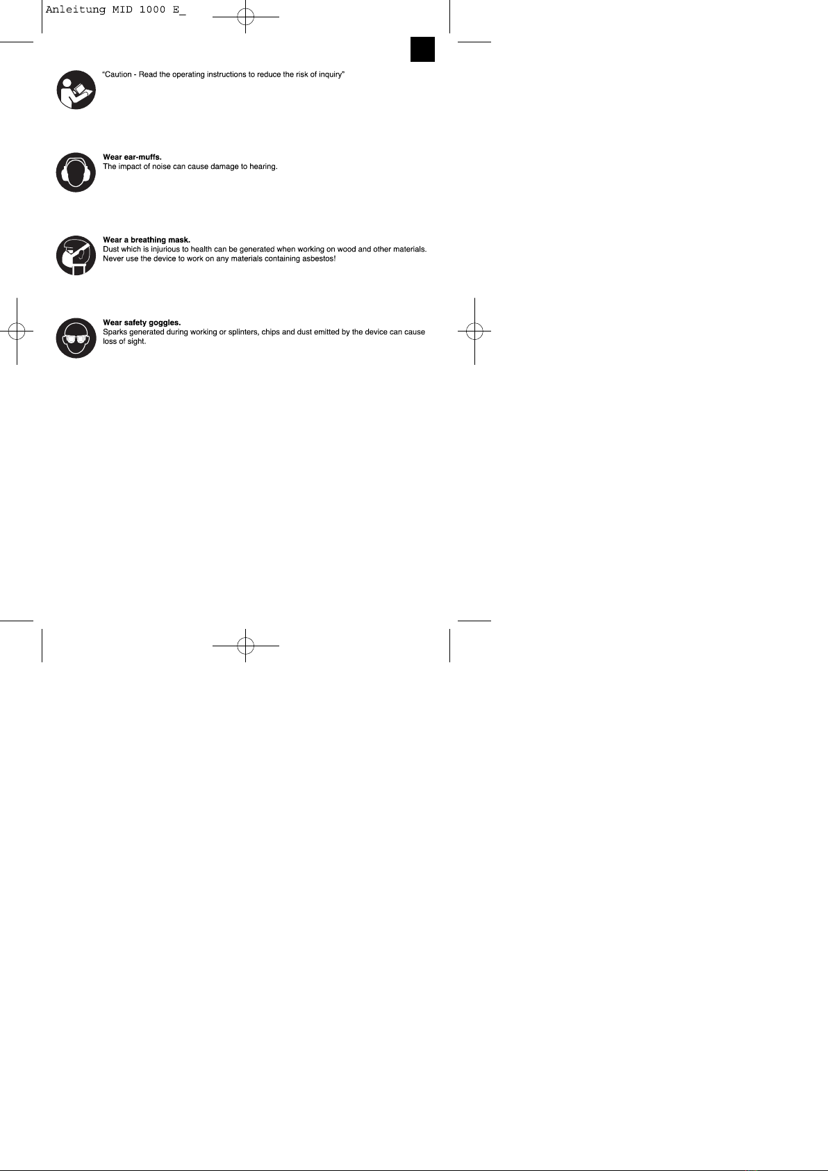
5.2 Fitting and adjusting the depth stop
Keep the noise emissions and vibrations to a (Fig. 4/Item 2)
minimum. The depth stop (2) is held in place by the additional
handle (8) by clamping. The clamp can be released
ŸOnly use appliances which are in perfect working and tightened by turning the handle.
order. ŸRelease the clamp and fit the depth stop (2) in the
ŸService and clean the appliance regularly. recess provided for it in the additional handle.
ŸAdapt your working style to suit the appliance. ŸSet the depth stop (2) to the same level as the drill
ŸDo not overload the appliance. bit.
ŸHave the appliance serviced whenever necessary. ŸPull the depth stop back by the required drilling
ŸSwitch the appliance off when it is not in use. depth.
ŸWear protective gloves. ŸTurn the handle on the additional handle (8) until it
is secure.
Residual risks ŸNow drill the hole until the depth stop (2) touches
the workpiece.
Even if you use this electric power tool in
accordance with instructions, certain residual 5.3 Fitting the drill bit (Fig. 5)
risks cannot be rules out. The following hazards
may arise in connection with the equipment's ŸAlways pull the power plug before making
construction and layout: adjustments to the equipment.
ŸRelease the depth stop (2) as described in 5.2 and
1. Lung damage if no suitable protective dust push it towards the drill handle. This provides free
is used. access to the chuck (1).
2. Damage to hearing if no suitable ear protection ŸUndo the chuck by turning it anti-clockwise with the
used. supplied chuck key (9).
3. Health damage caused by hand-arm vibrations ŸTo ensure that it is perfectly positioned the drill bit
the equipment is used over a prolonged period or tool should be inserted as far as possible into the
is not properly guided and maintained. chuck. After inserting the drill bit or tool, tighten the
chuck (1) by turning the chuck key (9) clockwise
5. Before starting the equipment until the drill bit or tool is secure. Check that the drill
bit is secure in the chuck (1).
Before you connect the equipment to the mains ŸCheck at regular intervals that the drill bit or tool is
supply make sure that the data on the rating plate secure (pull the mains plug).
are identical to the mains data.
Always pull the power plug before making
adjustments to the equipment. 6. Operation
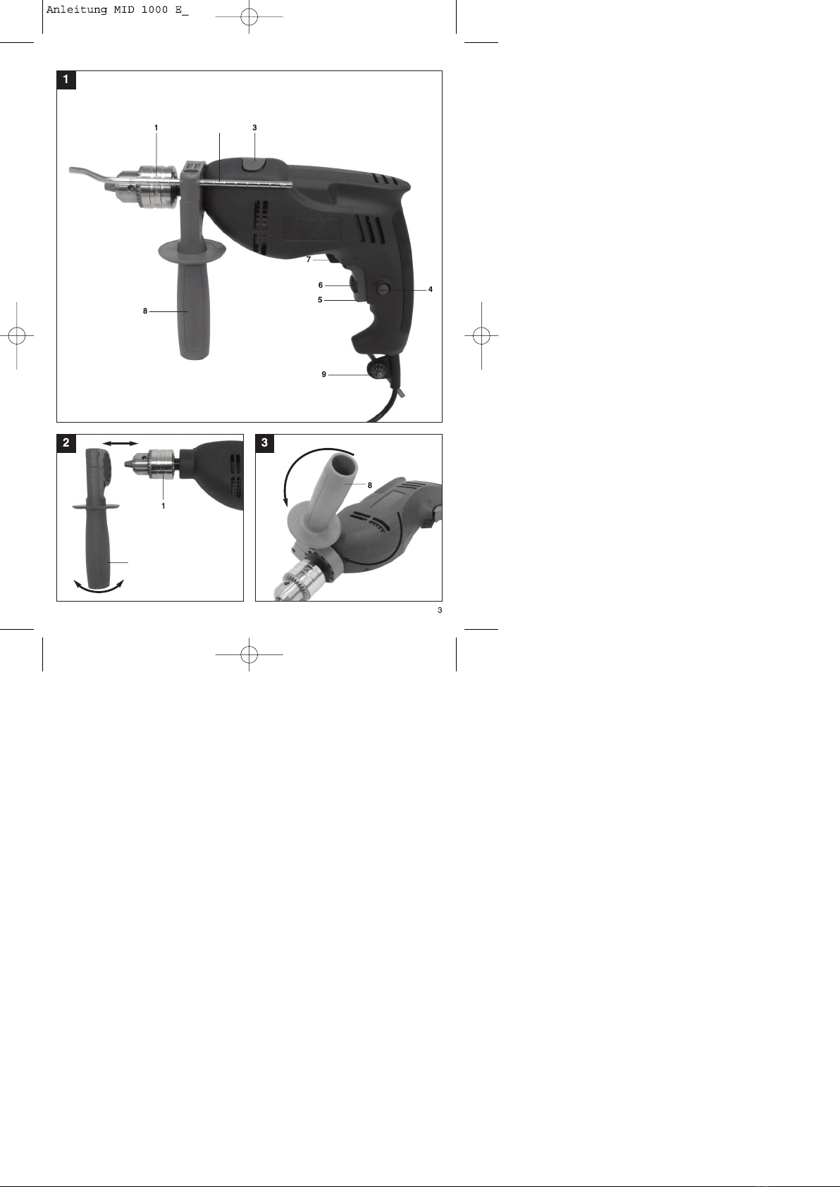
5.1. Fitting the additional handle (Fig. 2-3/Item 8) 6.1 ON/OFF switch (Fig. 6/Item 5)
ŸFirst fit a suitable drill bit into the tool (see 5.3).
The additional handle (8) enables you to achieve
better stability whilst using the hammer drill. Do not ŸConnect the mains plug to a suitable socket.
use the tool without the additional handle. ŸPosition the drill in the position you wish to drill.
The additional handle (8) is secured to the hammer
drill by a clamp. During the handle clockwise tightens To switch on:
this clamp. Turning it anti-clockwise will release the Press the ON/OFF switch (5)
clamp.
7
GB

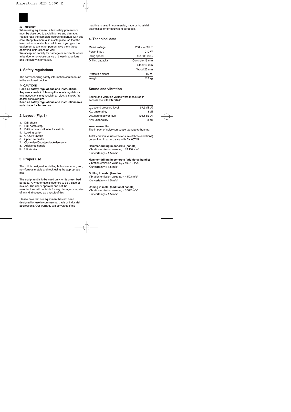
Continuous operation: Use for: Wood, metal, plastic
Secure the ON/OFF switch (5) with the locking Hammer drill
button (4). Drill / hammer drill selector switch (3) in the hammer
drill position. (Position B)
To switch off: Use for: Concrete, rock, masonry
Press the ON/OFF switch (5) briefly.
6.6 Tips for working with your hammer drill
Ÿ6.2 Adjusting the speed (Fig. 6/Item 5)
ŸYou can infinitely vary the speed whilst using the 6.6.1 Drilling concrete and masonry
tool. ŸSwitch the Drill/Hammer drill selector switch (3) to
ŸSelect the speed by applying a greater or lesser position B (Hammer drill).
pressure to the ON/OFF switch (5). ŸAlways use carbide drill bits and a high speed
ŸSelect the correct speed: The most suitable speed setting for drilling into masonry and concrete.
depends on the workpiece, the type of use and the
drill bit used. 6.6.2 Drilling steel
ŸLow pressure on the ON/OFF switch (5): Lower ŸSwitch the drill / hammer drill selector switch (3) to
speed (suitable for: small screws and soft position A (drill).
materials) ŸAlways use HSS drill bits (HSS = high speed steel)
ŸGreater pressure on the ON/OFF switch (5): and a low speed setting for drilling steel.
ŸHigher speed (suitable for large/long screws and ŸWe recommend that you lubricate the hole with a
hard materials) suitable cutting fluid to prevent unnecessary drill bit
wear.
Tip: Start drilling holes at low speed. Then increase
the speed in stages. 6.6.3 Inserting/Removing screws
ŸSwitch the Drill/Hammer drill selector switch (3) to
Benefits: position A (drill).
ŸThe drill bit is easier to control when starting the ŸUse a low speed setting
hole and will not slide away.
ŸYou avoid drilling messy holes (for example in tiles). 6.6.4 Starting holes
If you wish to drill a deep hole in a hard material
6.3 Preselecting the speed (Fig. 6/Item 6) (such as steel), we recommend that you start the
ŸThe speed setting ring (6) enables you to define the hole with a smaller drill bit.
maximum speed. The ON/OFF switch (5) can only
be pressed to the defined maximum speed setting. 6.6.5 Drilling tiles
ŸSet the speed using the setting ring (6) on the ŸTo start the hole, switch the drill / hammer drill
ON/OFF switch (5). selector switch (3) to position A (drill).
ŸDo not attempt to make this setting whilst the drill is ŸSwitch the drill / hammer drill selector switch (3) to
in use. position B (hammer drill) as soon as the drill bit has
passed through the tiles.
6.4 Clockwise/Counter-clockwise switch
(Fig. 6/Item 7)
ŸChange switch position only when the drill is at a 7. Replacing the power cable
standstill!
ŸSwitch the direction of the hammer drill using the If the power cable for this equipment is damaged, it
clockwise/counter-clockwise switch (7): must be replaced by the manufacturer or its aftersales
service or similarly trained personnel to avoid
Direction Switch position danger.
Clockwise (forwards and drill) R
Counter-clockwise (reverse) L
8. Cleaning, maintenance and
6.5 Drill / hammer drill selector switch
(Fig. 7/Item 3) ordering of spare parts
Change switch position only when the drill is at a Always pull out the mains power plug before starting
standstill! any cleaning work.
Drill 8.1 Cleaning
Drill / hammer drill selector switch (3) in the drill ŸKeep all safety devices, air vents and the motor
position. (Position A) housing free of dirt and dust as far as possible. Wipe
8
GB

the equipment with a clean cloth or blow itwith
compressed air at low pressure.
ŸWe recommend that you clean the device
immediately each time you have finished using it.
ŸClean the equipment regularly with a moist cloth and
some soft soap. Do not use cleaning agents or
solvents; these could attack the plastic parts of the
equipment. Ensure that no water can seep into the
device.
8.2 Carbon brushes
In case of excessive sparking, have the carbon
brushes checked only by a qualified electrician.
Important! The carbon brushes should not be rep
laced by anyone but a qualified electrician.
8.3 Maintenance
There are no parts inside the equipment which
require additional maintenance.
8.4 Ordering replacement parts:
Please quote the following data when ordering
replacement parts:
ŸType of machine
ŸArticle number of the machine
ŸIdentification number of the machine
ŸReplacement part number of the part required
For our latest prices and information please go to
www.isc-gmbh.info
9. Disposal and recycling
The unit is supplied in packaging to prevent its being
damaged in transit. This packaging is raw material
and can therefore be reused or can be returned to
the raw material system.
The unit and its accessories are made of various
types of material, such as metal and plastic.
Defective components must be disposed of as
special waste. Ask your dealer or your local council.
�
9
GB

“WARNUNG - Zur Verringerung des Verletzungsrisikos Bedienungsanleitung lesen”
Tragen Sie einen Gehörschutz.
Die Einwirkung von Lärm kann Gehörverlust bewirken.
Tragen Sie eine Staubschutzmaske.
Beim Bearbeiten von Holz und anderer Materialien kann gesundheitsschädlicher Staub
entstehen. Asbesthaltiges Material darf nicht bearbeitet werden!
Tragen Sie eine Schutzbrille.
Während der Arbeit entstehende Funken oder aus dem Gerät heraustretende Splitter, Späne
und Stäube können Sichtverlust bewirken.
10
D

11
D

Bohren in Metall (Zusatzhandgriff) 5.1. Zusatzhandgriff montieren (Bild 2-3/Pos. 8)
Schwingungsemissionswert ah = 5,372 m/s² Der Zusatzhandgriff (8) bietet Ihnen während der
Unsicherheit K = 1,5 m/s² Benutzung der Schlagbohrmaschine zusätzlichen
Halt. Benutzen Sie das Gerät daher nicht ohne den
Zusatzhandgriff.
Zusätzliche Informationen für
Elektrowerkzeuge Befestigt wird der Zusatzhandgriff (8) an der
Schlagbohrmaschine durch Klemmung. Durch
mWarnung! drehen des Griffes im Uhrzeigersinn wird die
Der angegebene Schwingungsemissionswert ist nach Klemmung angezogen. Drehen gegen den
einem genormten Prüfverfahren gemessen worden Uhrzeigersinn löst die Klemmung.
und kann sich, abhängig von der Art und Weise, in Ÿ Der beiliegende Zusatzhandgriff (8) muss zunächst
der das Elektrowerkzeug verwendet wird, ändern montiert werden. Hierzu ist durch Drehen des Griffes
und in Ausnahmefällen über dem angegebenen die Klemmung weit genug zu öffnen, damit der
Wert liegen. Zusatzhandgriff über das Bohrfutter (1) auf die
Schlagbohrmaschine geschoben werden kann.
Der angegebene Schwingungsemissionswert kann
zum Vergleich eines Elektrowerkzeuges mit einem Ÿ Nach dem Aufschieben des Zusatzhandgriffes (8)
anderen verwendet werden. schwenken Sie diesen in die für Sie angenehmste
Arbeitsposition.
Der angegebene Schwingungsemissionswert kann Ÿ Jetzt den Griff in entgegengesetzter Drehrichtung
auch zu einer einleitenden Einschätzung der wieder zudrehen, bis der Zusatzhandgriff fest sitzt.
Beeinträchtigung verwendet werden. Ÿ Der Zusatzhandgriff (8) ist für Rechtshänder ebenso
wie für Linkshänder geeignet.
Beschränken Sie die Geräuschentwicklung und
Vibration auf ein Minimum! 5.2 Tiefenanschlag montieren und einstellen
Ÿ Verwenden Sie nur einwandfreie Geräte. (Bild 4/Pos. 2)
Ÿ Warten und reinigen Sie das Gerät regelmäßig. Der Tiefenanschlag (2) wird vom Zusatzhandgriff (8)
durch Klemmung gehalten. Die Klemmung wird
Ÿ Passen Sie Ihre Arbeitsweise dem Gerät an. wieder durch Drehen des Griffes gelöst bzw.
Ÿ Überlasten Sie das Gerät nicht. festgezogen.
Ÿ Lassen Sie das Gerät gegebenenfalls überprüfen. Ÿ Lösen Sie die Klemmung und setzen Sie den
Ÿ Schalten Sie das Gerät aus, wenn es nicht benutzt Tiefenanschlag (2) in die dafür vorgesehene
wird. Aussparung des Zusatzhandgriffes ein.
Ÿ Tragen Sie Handschuhe. Ÿ Bringen Sie den Tiefenanschlag (2) auf gleiche
Ebene zum Bohrer.
Restrisiken Ÿ Ziehen Sie den Tiefenanschlag um die gewünschte
Bohrtiefe zurück.
Auch wenn Sie dieses Elektrowerkzeug Ÿ Drehen Sie den Griff des Zusatzhandgriffes (8)
vorschriftsmäßig bedienen, bleiben immer wieder zu bis dieser fest sitzt.
Restrisiken bestehen. Folgende Gefahren
können im Zusammenhang mit der Bauweise und Ÿ Bohren Sie nun das Loch, bis der Tiefenanschlag (2)
Ausführung dieses Elektrowerkzeuges auftreten: das Werkstück berührt.
1. Lungenschäden, falls keine geeignete
Staubschutzmaske getragen wird. 5.3 Einsetzen des Bohrers (Bild 5)
2. Gehörschäden, falls kein geeigneter Gehörschutz ŸZiehen Sie immer den Netzstecker, bevor Sie
getragen wird. Einstellungen am Gerät vornehmen.
3. Gesundheitsschäden, die aus Hand-Arm- ŸTiefenanschlag (2) wie in 5.2 beschrieben lösen und
Schwingungen resultieren, falls das Gerät über in Richtung Bohrergriff schieben. Somit hat
einen längeren Zeitraum verwendet wird oder Ÿman freien Zugang zum Bohrfutter (1). Das
nicht ordnungsgemäß geführt und gewartet wird. Bohrfutter mit dem mitgelieferten Spannschlüssel (9)
gegen den Uhrzeigersinn öffnen.
5. Vor Inbetriebnahme ŸFür einen optimalen Sitz sollte der Bohrer bzw. das
Werkzeug so weit wie möglich in das Bohrfutter
Überzeugen Sie sich vor dem Anschließen, dass die hineingesetzt werden. Ziehen Sie nach Einsetzen
Daten auf dem Typenschild mit den Netzdaten des Bohrers bzw. Werkzeuges das Bohrfutter (1) im
übereinstimmen. Uhrzeigersinn mit dem Spannschlüssel (9) fest, bis
Ziehen Sie immer den Netzstecker, bevor Sie der Bohrer bzw. das Werkzeug eingespannt ist.
Einstellungen am Gerät vornehmen. Prüfen Sie, ob der Bohrer fest im Bohrfutter (1) sitzt.
ŸÜberprüfen Sie in regelmäßigen Abständen den
12
D

festen Sitzt des Bohrers bzw. Werkzeuges (7) die Laufrichtung des
(Netzstecker ziehen!). Schlagbohrers ein:
Laufrichtung Schalterposition
6. Bedienung Rechtslauf (Vorwärts und Bohren) R
Linkslauf (Rücklauf) L
6.1 Ein/Ausschalter (Bild 6/Pos. 5)
Ÿ Setzen Sie zuerst einen geeigneten Bohrer in das 6.5 Bohren/Schlagbohren-Umschalter
Gerät ein (siehe 5.3). (Bild 7/Pos. 3)
Ÿ Verbinden Sie den Netzstecker mit einergeeigneten ŸNur im Stillstand umschalten!
Steckdose.
Ÿ Setzen Sie die Bohrmaschine direkt an der Bohren:
Bohrstelle an. Bohren-/Schlagbohren-Umschalter (3) in Stellung
Bohren. (Position A)
Einschalten: Anwendung: Hölzer; Metalle; Kunststoffe
Ein-/Ausschalter (5) drücken
Schlagbohren:
Dauerbetrieb: Bohren-/Schlagbohren-Umschalter (3) in Stellung
Ein-/Ausschalter (5) mit Feststellknopf (4) sichern. Schlagbohren. (Position B)
Anwendung: Beton; Gestein; Mauerwerk
Ausschalten:
Ein-/Ausschalter (5) kurz eindrücken. 6.6 Tipps für das Arbeiten mit Ihrer
Schlagbohrmaschine
6.2 Drehzahl einstellen (Bild 6/Pos. 5)
ŸSie können die Drehzahl während des Betriebes 6.6.1 Bohren von Beton und Mauerwerk
stufenlos steuern. ŸStellen Sie den Bohren/Schlagbohren Umschalter (3)
ŸDurch mehr oder wenig starkes Drücken des Ein- auf die Position B (Schlagbohren).
/Ausschalters (5) wählen Sie die Drehzahl. ŸBenutzen Sie für das Bearbeiten von Mauerwerk
ŸWahl der richtigen Drehzahl: Die am besten oder Beton immer Hartmetallbohrer und eine hohe
geeignete Drehzahl ist abhängig vom Werkstück, Drehzahleinstellung.
von der Betriebsart und vom eingesetzten Bohrer.
ŸGeringer Druck auf Ein-/Ausschalter (5): niedrigere 6.6.2 Bohren von Stahl
Drehzahl (Geeignet für: kleine Schrauben, weiche ŸStellen Sie den Bohren/Schlagbohren Umschalter (3)
Werkstoffe) auf die Position A (Bohren).
ŸGrößerer Druck auf Ein-/Ausschalter (5): höhere ŸBenutzen Sie für das Bearbeiten von Stahl immer
Drehzahl (Geeignet für: große/lange Schrauben, HSS-Bohrer (HSS = Hochlegierter
harte Werkstoffe) Schnellarbeitsstahl) und eine niedrige
Drehzahleinstellung.
Tipp: Bohren Sie Bohrlöcher mit geringer Drehzahl ŸEs ist empfehlenswert die Bohrung durch ein
an. Erhöhen Sie Die Drehzahl danach schrittweise. geeignetes Kühlmittel zu schmieren um unnötigen
Bohrerverschleiß zu vermeiden.
Vorteile:
ŸDer Bohrer ist beim Anbohren leichter zu 6.6.3 Schrauben eindrehen/lösen
kontrollieren und rutscht nicht ab. ŸStellen Sie den Bohren/Schlagbohren Umschalter (3)
ŸSie vermeiden zersplitterte Bohrlöcher (z.B. bei auf die Position A (Bohren).
Kacheln). ŸBenutzen Sie eine niedrige Drehzahleinstellung.
6.3 Vorwählen der Drehzahl (Bild 6/Pos. 6) 6.6.4 Löcher anbohren
ŸDer Drehzahl-Einstellring (6) ermöglicht es Ihnen, die Falls Sie ein tiefes Loch in ein hartes Material (wie
maximale Drehzahl zu definieren. Der Ein- etwa Stahl) bohren möchten, empfehlen wir, dass
/Ausschalter (5) kann nur noch bis zur Sie das Loch mit einem kleineren Bohrer vorbohren.
vorgegebenen Maximaldrehzahl eingedrückt
werden. 6.6.5 Bohren in Fliesen und Kacheln
ŸStellen Sie die Drehzahl mit dem Einstellring (6) im ŸStellen Sie zum Anbohren den Umschalter
Ein-/Ausschalter (5) ein. Bohren/Schlagbohren (3) auf die Position A
ŸNehmen Sie diese Einstellung nicht während des (Bohren).
Bohrens vor. ŸStellen Sie den Umschalter Bohren/Schlagbohren (3)
auf die Position B (Schlagbohren), sobald der Bohrer
6.4 Rechts-/Linkslauf-Umschalter (Bild 6/Pos. 7) die Fliese/Kachel durchschlagen hat.
Nur im Stillstand umschalten!
ŸStellen Sie mit dem Rechts-/Linkslauf- Umschalter
13
D

verschiedenen Materialien, wie z.B. Metall und
Kunststoffe. Führen Sie defekte Bauteile der
7. Austausch der Netzanschlussleitung Sondermüllentsorgung zu. Fragen Sie im
Fachgeschäft oder in der Gemeindeverwaltung nach!
Wenn die Netzanschlussleitung dieses Gerätes
beschädigt wird, muss sie durch den Hersteller oder
seinen Kundendienst oder eine ähnlich qualifizierte
Person ersetzt werden, um Gefährdungen zu
vermeiden.
8. Reinigung, Wartung und
Ersatzteilbestellung
Ziehen Sie vor allen Reinigungsarbeiten den
Netzstecker.
8.1 Reinigung
ŸHalten Sie Schutzvorrichtungen, Luftschlitze und
Motorengehäuse so staub- und schmutzfrei wie
möglich. Reiben Sie das Gerät mit einem sauberen
Tuch ab oder blasen Sie es mit Druckluft bei
niedrigem Druck aus.
ŸWir empfehlen, dass Sie das Gerät direkt nach jeder
Benutzung reinigen.
ŸReinigen Sie das Gerät regelmäßig mit einem
feuchten Tuch und etwas Schmierseife. Verwenden
Sie keine Reinigungs- oder Lösungsmittel; diese
könnten die Kunststoffteile des Gerätes angreifen.
Achten Sie darauf, dass kein Wasser in das
Geräteinnere gelangen kann.
8.2 Kohlebürsten
Bei übermäßiger Funkenbildung lassen Sie die
Kohlebürsten durch eine Elektrofachkraft überprüfen.
Achtung! Die Kohlebürsten dürfen nur von einer
Elektrofachkraft ausgewechselt werden.
8.3 Wartung
Im Geräteinneren befinden sich keine weiteren zu
wartenden Teile.
8.4 Ersatzteilbestellung:
Bei der Ersatzteilbestellung sollten folgende
Angaben gemacht werden;
ŸTyp des Gerätes
ŸArtikelnummer des Gerätes
ŸIdent-Nummer des Gerätes
ŸErsatzteilnummer des erforderlichen Ersatzteils
Aktuelle Preise und Infos finden Sie unter
www.isc-gmbh.info
9. Entsorgung und Wiederverwertung
Das Gerät befindet sich in einer Verpackung um
Transportschäden zu verhindern. Diese Verpackung
ist Rohstoff und ist somit wieder verwendbar oder
kann dem Rohstoffkreislauf zurückgeführt werden.
Das Gerät und dessen Zubehör bestehen aus
14
D

ş şş
ş
15
RO

mAtenţie!
La utilizarea aparatelor trebuie respectate cateva 4. Date tehnice
măsuri de siguranţă, pentru a evita accidentele şi
daunele. De aceea, citiţi cu grijă instrucţiunile de
utilizare/indicaţiile de siguranţă. Păstraţi aceste
materiale în bune condiţii, pentru ca aceste informaţii
să fie disponibile in orice moment. Dacă predaţi
aparatul altor persoane, înmanaţi-le şi aceste
instrucţiuni de utilizare /indicaţii de siguranţă. Nu ne
asumăm nici o răspundere pentru accidente sau
daune care rezultă din nerespectarea acestor
instrucţiuni de utilizare şi a indicaţiilor de siguranţă.
1. Indicaoii de siguranoa
Indicaţiile de siguranţa aferente le gasiţi in broşura
anexata.
mAVERTIZARE! Zgomote şi vibraţii
Citiţi indicaţiile de siguranţă şi indrumările.
Nerespectarea indicaţiilor de siguranţă şi a Valorile nivelelor de zgomot şi de vibraţie au fost
îndrumărilor poate avea ca urmare electrocutare, calculate conform EN 60745.
incendiu şi/sau răniri grave.
Păstraţi pentru viitor toate indicaţiile de
siguranţă şi îndrumările.
2. Descrierea aparatului (vezi Figura 1)
1. Mandrină
2. Opritor adancime de găurire
3. Comutator găurire / percuţie Purtaţi protecţie antifonică.
4. Buton de fixare Expunerea la zgomot poate cauza deteriorarea sau
5. Întrerupător pornire/oprire pierderea auzului.
6. Reglor al turaţiei
7. Comutator rotire stanga/dreapta Valorile totale ale nivelului de vibraţii (suma vectorială
8. Maner suplimentar a trei direcţii), calculate conform EN 60745.
9. Cheie mandrină
Găurire prin percuţie in beton (maner) 2
Valoare a vibraţiilor emise ah = 13,192 m/s
3. Utilizarea conform scopului 2
Nesiguranţă K = 1,5 m/s
Maşina de găurit este construită pentru găurirea Găurire prin percuţie in beton (măner
lemnului, fierului, a metalelor neferoase şi a pietrei cu suplimentar)
utilizarea sculelor de găurit corespunzătoare. 2
Valoare a vibraţiilor emise a = 10,910 m/s
h
2
Nesiguranţă K = 1,5 m/s
Maşina se va utiliza numai conform scopului pentru
care este concepută. Orice altă utilizare nu este în Găurire în metal (măner)
conformitate cu scopul. Pentru pagubele sau 2
Valoare a vibraţiilor emise a = 4,503 m/s
h
vătămările rezultate în acest caz este responsabil 2
Nesiguranţă K = 1,5 m/s
utilizatorul/operatorul şi nu producătorul.
Găurire în metal (măner suplimentar)
Vă rugăm să ţineţi cont de faptul că maşinile noastre 2
Valoare a vibraţiilor emise a = 5,372 m/s
nu sunt construite pentru utilizare în domeniile h
2
meşteşugăreşti şi industriale. Noi nu preluăm nici o Nesiguranţă K = 1,5 m/s
garanţie atunci când aparatul este folosit în
întreprinderile meşteşugăreşti sau industriale ori în
scopuri similare.
-1
0-3000 min
Nivelul presiunii sonorei LpA
Nesiguranţă KpA
Nivelul capacităţii sonore LWA
Nesigurantă KWA
97,5 dB(A)
3 dB
108,5 dB(A)
3 dB
16
RO

Ÿ Mănerul suplimentar anexat (8) trebuie mai întai
Informaţii suplimentare pentru scule electrice montat. Pentru aceasta trebuie ca prin rotirea
Avertisment! manerului să deschideţi clemele suficient de mult
pentru ca manerul suplimentar să poată fi impins
Valoarea vibraţiilor emise a fost măsurată conform peste mandrină (1) pe maşina de găurit prin
unui proces de verificare normat şi se poate modifica percuţie.
in funcţie de modul de utilizare a sculei electrice şi in Ÿ După poziţionarea manerului suplimentar (8)
cazuri excepţionale poate depăşi valoarea indicată. potriviţi-l în poziţia de lucru cea mai comodă pentru
Dvs..
Valoarea vibraţiilor emise poate fi utilizată pentru Ÿ Rotiţi acum manerul în sensul opus, pană cand se
comparaţia cu vibraţiile sculelor electrice ale altor blochează.
producători. Ÿ Manerul suplimentar (8) este indicat atat pentru
dreptaci cat şi pentru stangaci.
Valoarea vibraţiilor poate fi utilizată şi la o estimare
introductivă a afecţiunii aparatului. 5.2 Montarea şi reglarea opritorului adancimii de
găurire (Fig. 4/Poz. 2)
Limitaţi zgomotul şi vibraţiile la un nivel minim. Opritorul adancimii de găurire (2) este susţinut de
Ÿ· Utilizaţi numai aparate in stare ireproşabilă. către manerul suplimentar (8) cu ajutorul clemelor.
Ÿ· Intreţineţi şi curăţaţi aparatul cu regularitate. Clemele se deschid şi respectiv inchid prin rotirea
Ÿ· Adaptaţi modul dvs. de lucru aparatului. mănerului.
Ÿ· Nu suprasolicitaţi aparatul. Ÿ Deschideţi clemele şi introduceţi opritorul adancimii
Ÿ· Dacă este necesar, lăsaţi aparatul să fie verificat. de găurire (2) in lăcaşul special prevăzut pe
manerul suplimentar.
Ÿ· Decuplaţi aparatul, atunci cand acesta nu este
utilizat. Ÿ Aduceţi opritorul adancimii de găurire (2) la acelaşi
nivel cu burghiul.
Ÿ· Purtaţi mănuşi! Ÿ Trageţi opritorul cu exact adancimea de găurire
Riscuri reziduale dorită inapoi.
Riscurile reziduale nu pot fi eliminate complet, Ÿ Rotiţi manerul suplimentar (8) la loc, pană cand se
chiar dacă manipulaţi această sculă electrică in blochează din nou.
mod regulamentar. Următoarele pericole pot Ÿ Daţi acum o gaură şi inaintaţi pană cand opritorul
apărea, dependente de tipul constructiv şi adancimii de găurire (2) atinge piesa prelucrată.
execuţia acestei scule electrice:
1. Afecţiuni pulmonare, in cazul in care nu se poartă 5.3 Montarea burghiului (Fig. 5)
mască de protecţie impotriva prafului adecvată. Ÿ Scoateţi intotdeauna ştecherul din priză inainte de a
2. Afecţiuni auditive, in cazul in care nu se poartă efectua reglări ale aparatului.
protecţie antifonică corespunzătoare. Ÿ Desfaceţi opritorul adancimii de găurire (2) conform
3. Afecţiuni ale sănătăţii rezultate din vibraţia descrierii de la punctul 5.2 şi împingeţi-lin direcţia
manăbraţ, in cazul utilizării timp mai indelungat a manerului. Aveţi acum acces liber la mandrină (1).
aparatului sau a utilizării şi intreţinerii sale Ÿ Desfaceţi mandrina în sens antiorar cu ajutorul cheii
necorespunzătoare. pentru mandrină (9) livrate.
Ÿ Pentru a asigura o poziţie stabilă burghiul respectiv
5. Înainte de punerea în funcţiune scula trebuie introduse pană la refuz in mandrină.
După introducerea burghiului respectiv a sculei
Asiguraţi-vă inainte de racordare că datele de pe strangeţi mandrina (1) in sensul acelor de ceasornic
plăcuţa de identificare corespund datelor din reţea. cu cheia pentru mandrină (9) pană cand burghiul
resp. scula sunt bine fixate.
Scoateţi intotdeauna ştecherul din priză înainte de a Ÿ Verificaţi dacă burghiul este bine fixat în mandrină
executa reglaje la maşină.(1).
Ÿ Verificaţi la intervale regulate de timp dacă burghiul,
5.1.Montarea mănerului suplimentar respectiv scula sunt bine prinse in mandrină
(Fig. 2-3/Poz. 8) (decuplaţi ştecherul de la reţea!).
Mănerul suplimentar (8) vă oferă stabilitate
suplimentară in timpul utilizării maşinii de găurit cu
percuţie. Din acest motiv nu folosiţi maşina fără 6. Operare
manerul suplimentar.
Fixarea mănerului suplimentar (8) la maşina de găurit 6.1 Întrerupător pornire/oprire (Fig. 6/Poz. 5)
cu percuţie se face cu ajutorul clemelor. Prin rotirea Ÿ Montaţi mai întai un burghiu potrivit în maşină (vezi
manerului în sens orar se strang clemele. Prin rotirea 5.3).
în sens antiorar se desface fixarea mănerului. Ÿ Racordaţi cablul de reţea la o priză adecvată.
17
RO

Sensul de lucru al maşinii Poziţia comutatorului
Ÿ Aşezaţi maşina de găurit pe punctul unde urmează Rotaţie spre dreapta (înainte şi găurire) R
să se dea gaura. Rotaţie spre stanga (înapoi) L
Pornire: 6.5 Comutator găurire/percuţie (Fig. 7/Poz. 3)
Apăsaţi intrerupătorul pornire/oprire (5) Ÿ Comutarea se va realiza numai cănd aparatul
este în repaus!
Funcţionarea de durată:
Asiguraţi intrerupătorul pornire/oprire (5) cu butonul Găurire:
de fixare (4). Comutatorul găurire/percuţie (3) este în poziţia
găurire. (Poziţia A)
mAtenţie! Un blocaj este posibil doar în cazul rotaţiei Utilizare: lemn; metale; materiale plastice
spre dreapta.
Găurire prin percuţie:
Oprire: Comutatorul găurire/percuţie (3) este în poziţia
Apăsaţi scurt intrerupătorul pornire/oprire (5). percuţie. (Poziţia B)
Utilizare: beton; piatră; zidărie
6.2 Reglarea turaţiei (Fig. 6/Poz. 5)
Ÿ În timpul utilizării maşinii de găurit puteţi regla turaţia 6.6 Ponturi pentru lucrul cu maşina de găurit cu
acesteia fără trepte. percuţie
Ÿ Prin apăsarea mai tare sau mai uşoară a 6.6.1 Găurire în beton şi zidărie
intrerupătorului pornire/oprire (5) alegeţi turaţia. Ÿ Poziţionaţi comutatorul găurire/percuţie (3) in poziţia
Ÿ Alegerea turaţiei corecte: Turaţia adecvată depinde B (găurire prin percuţie).
de piesa de prelucrat, de regimul de funcţionare şi Ÿ În cazul zidăriei sau al betonului utilizaţi întotdeauna
de burghiul folosit. burghie pentru metale dure şi o turaţie ridicată.
Ÿ Apăsare uşoară pe intrerupătorul pornire/oprire (5):
turaţie joasă (adecvată pentru: şuruburi mici, 6.6.2 Găurire in oţel
materiale de prelucrat moi) Ÿ Poziţionaţi comutatorul găurire/percuţie (3) in poziţia
Ÿ Apăsare mai tare pe intrerupătorul pornire/oprire (5): A (găurire).
turaţie mai mare (adecvată pentru: şuruburi Ÿ În cazul oţelului utilizaţi intotdeauna burghie HSS
mari/lungi, materiale dure) (HSS = oţel rapid, înalt aliat) şi o turaţie joasă.
Ÿ Este recomandată ungerea găurii cu un agent de
răcire adecvat, pentru a evita uzura inutilă a maşinii
Pont: Folosiţi o turaţie mai mică atunci cand incepeţide găurit şi a burghiului.
să daţi gaura. Creşteţi apoi treptat turaţia.
6.6.3 Strangerea/Desfacerea şuruburilor
Avantaje: Ÿ Poziţionaţi comutatorul găurire/percuţie (3) in poziţia
Ÿ Cand incepeţi să daţi gaura, burghiul este mai uşor
de controlat şi nu alunecă. A (găurire).
Ÿ Evitaţi astfel găurile aşchiate (de ex. la plăcile de Ÿ Folosiţi o turaţie joasă.
teracotă).
6.6.4 Găuri pregătitoare
6.3 Preselecţia turaţiei (Fig. 6/Poz. 6) În cazul în care doriţi să daţi o gaură adancă într-un
Ÿ Inelul de reglare a turaţiei (6) vă permite definirea material dur (cum ar fi oţelul), vă recomandăm să daţi
turaţiei maxime. Întrerupătorul de pornire/oprire (5) mai întai o gaură pregătitoare cu un burghiu mai mic
nu mai poate fi apăsat decat pană la turaţia maximă în punctul respectiv.
prestabilită. 6.6.5 Găurire în faianţă, gresie şi plăci deteracotă
Ÿ Alegeţi turaţia maximă cu ajutorul inelului de reglare Ÿ Aduceţi comutatorul de găurire/percuţie (3) în poziţia
a turaţiei (6) aflat în dreptul întrerupătorului de
pornire/oprire (5). A (găurire) pentru a da gaura pregătitoare.
Ÿ Nu efectuaţi acest reglaj în timpul procesului de Ÿ Aduceţi comutatorul de găurire/percuţie (3) în poziţia
găurire. B (găurire prin percuţie) imediat ce burghiul a
străpuns gresia/faianţa/placa de teracotă.
6.4 Comutatorul rotire stanga/dreapta
(Fig. 6/Poz. 7) 7. Schimbarea cablului de racord la
Ÿ Comutarea se va realiza numai cand aparatul este reţea
în repaus!
Ÿ Alegeţi sensul de lucru al maşinii de găurit prin În cazul deteriorării cablului de racord la reţea a
percuţie cu ajutorul comutatorului rotire spre acestui aparat, pentru a evita pericolele acesta
stanga/rotire spre dreapta (7): trebuie înlocuit de către producător sau un scervice
18
RO

clienţi sau de opersoană cu calificare similară.
8. Curăţirea, întreoinerea şi comanda
pieselor de schimb
Scoateoi ştecherul înaintea începerii lucrărilor de
curăoire.
8.1 Curăţirea
Ÿ Păstraţi curate dispozitivele de protecţie, şliţele de
aerisire şi carcasa maşinii. Îtergeţi aparatul cu o
cărpă curată sau suflaţi praful cu aer sub presine la
o presine mică.
Ÿ Noi recomandăm curaţirea aparatului imediat după
fiecare folosire.
Ÿ Curăoaţi aparatul cu o cărpă umedă şi puţin săpun
lichid. Nu folosiţi detergenţi sau solvenţi; aceştia pot
ataca piesele din material plastic ale aparatului. Fiţi
atenţi să nu intre apă in interiorul aparatului.
8.2 Periile de cărbune
În cazul formării excesive a scanteilor periile de
cărbune se vor verifica de către un electrician spe
cializat.
Atenţie! Periile de carbune au voie să fie schimba
te numai de către un electrician specializat.
8.3 Întreoinerea
În interiorul aparatului nu se găsesc alte piese
care trebuiesc întreţinute.
8.4 Comanda pieselor de schimb:
La comanda pieselor de schimb trebuiesc
menoionate urmatoarele date;
Ÿ Tipul aparatului
Ÿ Numărul articolului aparatului
Ÿ Numărul Ident al aparatului
Ÿ Numărul piesei de schimb necesare
Preţurile actuale şi informaţii suplimentare găsiţi la
www.isc-gmbh.info
9. Îndepărtarea şi reciclarea
Aparatul se găseşte într-un ambalaj pentru a se
preveni deteriorările pe timpul transportului. Acest
ambalaj este o resursă şi deci refolosibil şi poate fi
supus unui ciclu de reciclare.
Aparatul şi auxiliarii acestuia sunt fabricaţi din
materiale diferite cum ar fi de exemplu metal şi
material plastic. Piesele defecte se vor preda la un
centru de colectare pentru deşeuri speciale.
Interesaoi-va in acest sens in magazinele de
specialitate sau la administraoia locala!
19
RO

„İkaz – yaralanma riskini azaltmak için Kullanma Talimatını okuyunuz“
Kulaklık takın.
Çalışma esnasında oluşan gürültü işitme kaybına yol açabilir.
Toz maskesi takın.
Ahşap ve diğğer malzemeler üzerinde çalışıldığında sasağlığa zarar veren tozlar oluşabilir. Asbest
içeren malzemelerin işlenmesi yasaktır!
İş gözlüğü kullanın.
Çalışma esnasında oluşan kıvılcım veya aletten dışarı fırlayan kıymık, talaş ve tozlar gözlere
zarar verebilir.
20
TR
This manual suits for next models
1
Table of contents
Languages:
Other Maestro Drill manuals
Popular Drill manuals by other brands

DeWalt
DeWalt DCD700 Original instructions

Makita
Makita HB500 Original instruction

HIKOKI
HIKOKI DS 36DA Handling instructions

Bosch
Bosch 13614-2G - 14.4V Brute Tough Cordless Operating/safety instructions

Parkside
Parkside SCHLAGBOHRMASCHINE PSBM 500 A1 Operation and safety notes

Porter-Cable
Porter-Cable 873 instruction manual