MAGLOGIX MagnaDrill MX-V User manual

Operation Manual
MagnaDrill®MX-V
Universal Magnetic Drill Stand

2
Contents
Safety Instructions, Proper Use 10
Technical Data, Available Accessories 11
Description 12
Start-up 13
Special Information on Handling Switchable Permanent Magnets 14
Maintenance and Inspection 15
CE Declaration of Conformity 16
Before use read and save these instructions!

3
Dear customer,
Thank you for purchasing a Maglogix®product. Read these operation instructions closely before using your device
for the first time and keep them for later reference.
Safety Instructions
During work with this machine, improper handling and/or poor maintenance result in significant hazards which can
lead to destruction of the machine and serious accidents with considerable injuries. Observe all safety instructions
of this operation manual and contact the manufacturer if you have any questions.
Always...
activate the switchable permanent magnet completely
activate the magnet on metallic, ferromagnetic materials
use the whole magnetic surface for working
work on plane surfaces
clean the magnetic surface and keep it clear of dirt, swarf and welding sputter
set the magnetic drill stand down gently to prevent damage to the magnetic surface
secure yourself with a safety belt when drilling on walls or ceilings
follow the instructions in the operation manual
familiarise new users with the safe use of the machine
wear safety goggles and ear protection during work
use safety guard if supplied
observe local, country-specific guidelines
store in a dry place
Never...
drill without first having activated the magnet
work on round or curved objects
drill several workpieces on top of one another
modify the machine or remove signs
use the machine when damaged or when parts are missing
strain or damage the underside of the magnet through heavy impact or blows
use the machine without having been properly instructed
operate the machine without having read and understood the complete operation manual
use the drill stand to support, lift or transport persons or loads
store or operate at temperatures above 50°C (122°F)
leave the machine hanging unsupervised
allow the machine to come into contact with corrosive materials
People with cardiac pacemakers or other medical appliances may only use the magnetic drill
stand following approval by their physician.
Never touch rotating parts! Keep hands and fingers away from the work area while the motor
is running! Failure to do so can result in severe injuries!

4
Proper Use
This MagnaDrill®MX-V magnetic drill stand with a tool holder of Ø 43 mm (Euro collar) and a switchable Maglogix®
MXL permanent magnet is intended for use with wired, mains-operated drilling machines. Combined with a drilling
machine, this magnetic drill stand is destined to be used with core or solid drills on ferromagnetic workpieces. It
may only be used in a dry environment which is protected from the weather. The machine may be used
horizontally, vertically or overhead.
Technical Data
Prod.-no. and designation:
MagnaDrill® MX-V Drill Stand
Collar:
Ø 43 mm Euro standard
Ø 1.69“ Euro standard
Max. drilling Ø in steel
- Core drill:
- Twist drill:
12 - 35 mm
up to Ø13 mm DIN 338
½“ – 1 38
⁄“
½“
Stroke:
105 mm + 80 mm height adjustment
at slide
4 18
⁄
“
+ 318
⁄“height adjustment
at slide
3
Size of magnetic base:
72 x 190 mm
2 ¾“ x 7 ½“
Magnetic holding force:
7500 N
1686 lbs
Tool force:
(on 10 mm steel)
2800 N
630 lbs @ 3/8” steel
Tool force:
(on 6 mm steel)
2300 N
520 lbs @ 2/8” steel
Min. material thickness:
3 mm
1/8“
Weight:
7 kg
15 lbs
Available accessories
Prod.-no.
Carrying case
02120.K
Coolant ALFRA BIO 4000
21040
Coolant equipment
189412029
Safety guard
189414052
Chuck with Weldon shank up to 13 mm
18107
Safety belt
189490501
Allen key 2.5 mm
DIN911-2,5
Allen key 4.0 mm
DIN911-4
Allen key 6.0 mm
DIN911-6
Swarf hook
189480022

5
Desciption
The MagnaDrill®MX-V drill stand can be attached to ferromagnetic workpieces using the installed mechanically
switchable MXL permanent magnet (D). For this purpose, the magnetic lever (G) must be pressed downwards and
the safety tab (F) must latch into place correctly. A self-adjusting dovetail guide (C) which the collar (A) is attached
to can be vertically adjusted using the star handle (H). Wired, mains-operated drilling machines can be fixed tightly
to this collar (Ø 43 mm).
As an additional torque support there is a nose on the collar in order to engage the drilling machine into the collar.
The type plate and an attachment possibility for the Allen keys included can be found on the back of the machine.
A) Tool holder (Ø 43 mm)
G) Lever for magnet
B) Quick clamping lever
H) Star handle
C) Slide and setting screws
for adjustment on the back
D) Magnetic base
E) Recess for safety belt
F) Safety tab

6
Start-up
You have received a completely assembled MX-V drill stand and detailed operation manual. Please check the
condition of the goods on receipt for any transport damage, and make sure the delivery is complete. Otherwise
contact the manufacturer immediately.
Always read the operation manual before using the device for the first time!
1. First, open the quick clamping lever and set the drilling machine as complete as possible into the tool holder.
The nose (see red mark) should be used as a torque support to avoid inadvertent twisting of the drilling
machine.
2. Close the quick clamping lever tightly.
3. The lever of the switchable permanent magnet is pointing upwards. The magnet is deactivated so that you can
position the machine. A slight magnetic pre-tension helps with alignment of the machine on vertical walls or for
overhead work. Secure the drilling unit using the safety belt when working on walls and ceilings.
4. Press the lever down as far as it will go. Make sure that the safety tab audibly latches into place. The magnet
is now activated.
Before drilling, make sure that the lever of the magnet is in the ON position.
5. After having activated the magnet, insert the plug of the drilling machine in the mains socket and turn the
motor on.
6. Turn the star handle to lower the motor and the rotating drill slowly to the workpiece. Ensure sufficient
cooling during the drilling process.
7. When you have finished drilling, move the motor upwards by turning the star handle. Deactivate the motor
of the drilling machine and pull the plug.
8. Once the motor has come to a complete standstill, remove swarf and other drilling waste.
9. To deactivate the permanent magnet, press the black safety tab inwards using the ball of your hand and lift
the lever up. Then clean the underside of the magnet of swarf or any other residue stuck to it.
Use a swarf hook to remove the swarf. Do not touch with your bare hands. Risk of injury!

7
Special Information on Handling Switchable Permanent Magnets
The magnetic surface of the incorporated Maglogix® MXL permanent magnet is located on the underside of the
magnetic drill stand and generates the magnetic holding force through magnetic flux when activated. The magnet
can be activated independently of the mains voltage by pressing the lever down. For the magnet to be released the
black safety tab must be pushed by using the ball of your hand and the lever pulled upwards. The machine remains
attached to the workpiece even in the event of a power failure.
Material thickness
The magnetic flux (north to south field lines) of the permanent magnet requires a minimum material thickness to
flow completely into and across the material below the magnetic contact area. Beyond this minimum material
thickness, the maximum holding force continues to decrease (see Detailed Performance Data, Table 1).
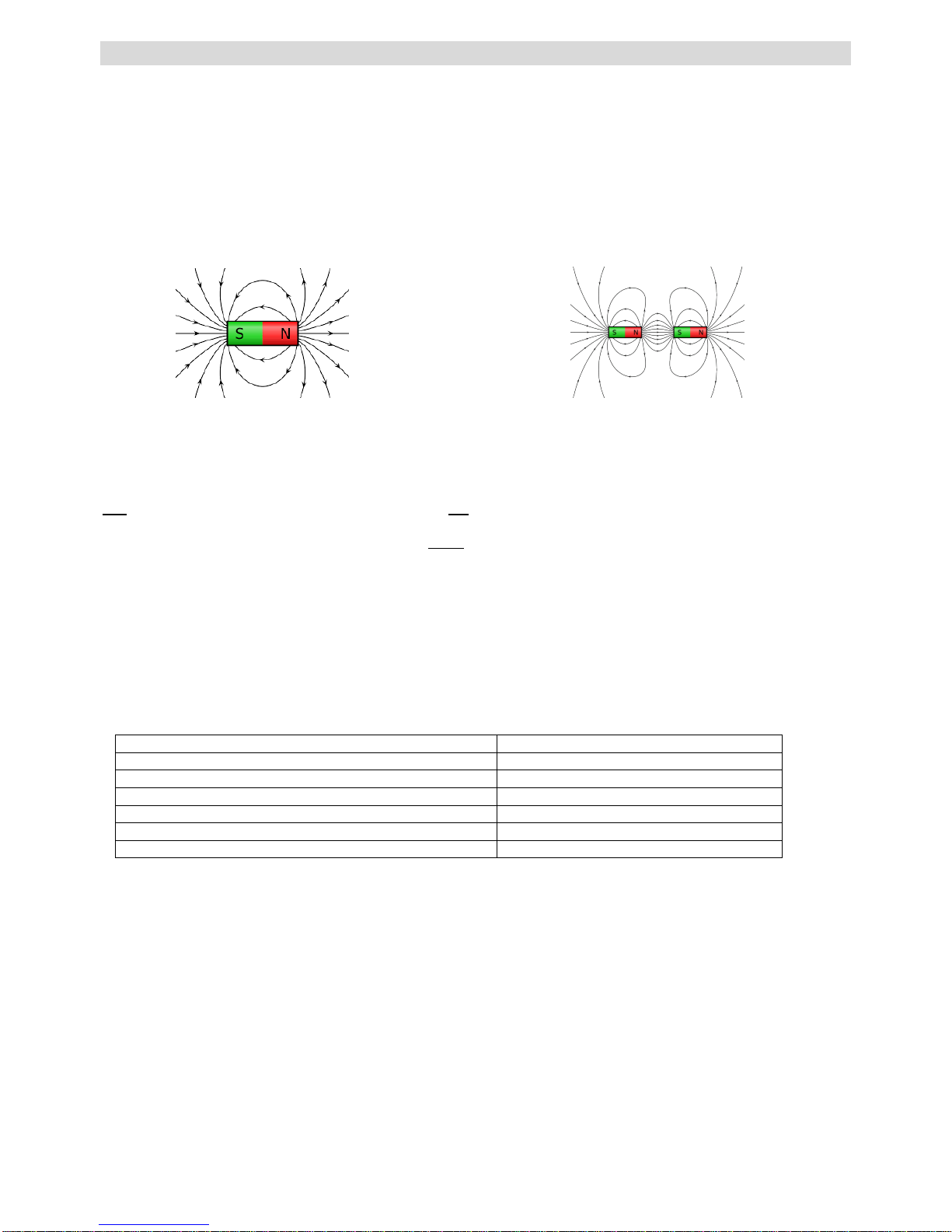
Conventional switchable permanent magnets have a deep penetrating singular (north to south) magnetic field. The
way conventional switchable permanent magnets hold onto steel would be similar to stapling paper together using
one large heavy staple in the center of the page, and not bending the legs together.
The compact multi-field magnetic array of the Maglogix®switchable permanent magnets would be similar to
stapling paper together in a circular pattern with many small lightweight staples close together, and bending the
legs together to achieve an even greater holding force. An infinate number of small magnetic field arrays are the
principle behind the Maglogix®patented switchable magnetic clamps.
Material
Every material reacts in different ways to the penetration of magnetic field lines. The breakaway force of the
magnetic contact area is determined by using common (low carbon) A36 steel. The given load-bearing capacity of
the magnet should be De-Rated based on Table 1. It is up to the user to determine adequate magnetic holding
force for alloys not shown in this table.
Table 1
Material
Magnetic force in %
Non-alloyed steel (0.1-0.3% C content, includes A36)
100
Non-alloyed steel (0.3-0.5% C content)
90-95
Cast steel
90
Grey cast iron
45
Nickel
11
Stainless steel, aluminium, brass
0
Surface quality
If a kind of “air gap” is produced between the magnet and the workpiece, this reduces the holding force. In the
same way, paint, rust, scale, surface coatings, grease or similar substances all form an air gap between the
workpiece and the switchable magnet, reducing the holding force.
Maximum operating temperature
The high-power permanent magnets installed in the magnetic clamp will maintain their load-bearing capacity up to
a maximum operating temperature of 176°F (80°C). Exceeding this maximum operational temperature may cause
irreversible damage.
Conventional (singular) switchable
permanent magnet
Maglogix®(multi-field) switchable
permanent magnet

8
Maintenance and Inspection
The user is obliged to maintain and service the drill stand and the drilling machine and in compliance with the
specifications in the operation manual and according to the country-specific standards and regulations.
The maintenance intervals are classified according to the frequency with which the maintenance should be carried
out.
Always disconnect the machine from the mains before any maintenance operation; otherwise
there is a risk of injury due to unintentional machine switch-on.
Before every use...
inspect the core drilling machine, drill stand and underside of the magnet for visible signs of damage
clean the surface of the workpiece and the underside of the magnet
check the blocking function of the safety tab on the lever
Weekly...
check that the operating lever and safety tab are working properly
check the underside of the magnet for scratches, pressure points or cracks. Have the magnet repaired by
the manufacturer if necessary
Monthly...
check the markings and labelling on the drill stand for legibility and damage. Replace them if necessary
clean all the sliding surfaces regularly, re-lubricate them and set the pre-tension of the slide
Maintenance, testing and repair work may only be carried out by qualified electricians according to the regulations
valid in the respective country.
Only use genuine Maglogix®spare parts.

9
Markus A. Döring
(Managing Director)
EC Declaration of Conformity
Herewith we,
Alfra GmbH
2. Industriestr. 10
68766 Hockenheim
declare that the universal magnetic drill stand
MagnaDrill®MX-V
corresponds to the following directives:
Machinery Directive: 2006/42/EC
Following directives or normative documents were applied:
Machine safety :
DIN EN ISO 12100:2011
Authorized for the compilation of the documents:
Alfra GmbH
2. Industriestr. 10
68766 Hockenheim, Germany
Hockenheim, 15.11.2017

10

11

12
Maglogix®LLC
11196 Cardinal Drive
Parker, CO. 80138
Phone: 303-257-7888
Internet: www.maglogix.com.
Email: info@maglogix.com
11/2017
Table of contents