As with MIG, direct current power sources
with constant voltage output characteristics
are normally employed to supply the welding
current.With flux-cored wires the terminal that
the filler wire is connected to depends on the
specific product being used, some wires running
electrode positive, others running electrode
negative.The work return is then connected to
the opposite terminal. It has also been found
that the output characteristics of the power
source can have an effect on the quality of the
welds produced.
The wire feed unit takes the filler wire from
a spool, and feeds it through the welding gun,
to the arc at a predetermined and accurately
controlled speed. Normally, special knurled feed
rolls are used with flux-cored wires to assist
feeding and to prevent crushing the consumable.
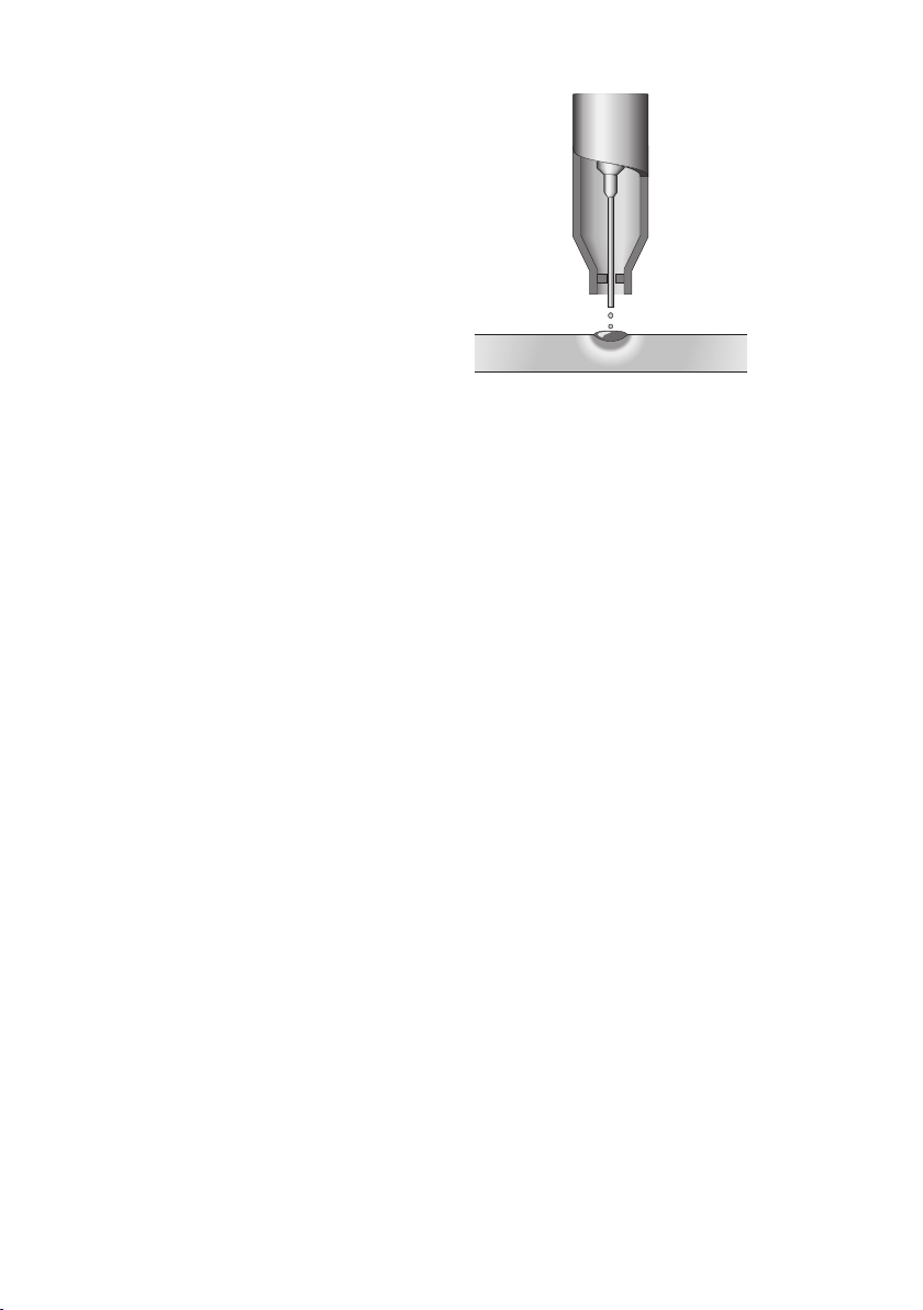
Unlike MIG, which uses a solid consumable
filler wire, the consumable used in FCAW is
of tubular construction, an outer metal sheath
being filled with fluxing agents plus metal
powder.The flux fill is also used to provide
alloying, arc stability, slag cover, de-oxidation,
and, with some wires, gas shielding.
In terms of gas shielding, there are two different
ways in which this may be achieved with the
FCAW process.
Additional gas-shielding supplied from an
■
external source, such as a gas cylinder
Production of a shielding gas by
■
decomposition of fluxing agents within the
wire, self-shielding
Gas shielded wires are available with either
a basic or rutile flux fill, while self-shielded
wires have a broadly basic-type flux fill.The
flux fill dictates the way the wire performs, the
properties obtainable, and suitable applications.
Gas-shielded Operation
Many cored wire consumables require an
auxiliary gas shield in the same way that solid
wire MIG consumables do.These types of wire
aregenerallyreferredtoas‘gas-shielded’.
Using an auxiliary gas shield enables the wire
designer to concentrate on the performance
characteristics, process tolerance, positional
capabilities, and mechanical properties of the
products.
In a flux cored wire the metal sheath is
generally thinner than that of a self-shielded
wire.The area of this metal sheath surrounding
the flux cored wire is much smaller than that of
a solid MIG wire.This means that the electrical
resistance within the flux cored wire is higher
than with solid MIG wires and it is this higher
electrical resistance that gives this type of wire
some of its novel operating properties.
One often quoted property of fluxed cored
wires are their higher deposition rates than
solid MIG wires.What is often not explained
is how they deliver these higher values and
whether these can be utilised. For example,
if a solid MIG wire is used at 250 amps, then
exchanged for a flux cored wire of the same
diameter, and welding power source controls
are left unchanged, then the current reading
would be much less than 250 amps, perhaps
as low as 220 amps.This is because of Ohms
Law that states that as the electrical resistance
increases if the voltage remains stable then the
current must fall.
To bring the welding current back to 250 amps
it is necessary to increase the wire feed speed,
effectively increasing the amount of wire
being pushed into the weld pool to make the
weld.Itisthisaffectthatproducesthe‘higher
deposition rates’ that the flux cored wire
manufacturers claim for this type of product.
Unfortunately in many instances the welder has
difficulty in utilising this higher wire feed speed
and must either increase the welding speed or
increase the size of the weld. Often in manual
applications neither of these changes can be
implemented and the welder simply reduces the
wire feed speed back to where it was and the
advantages are lost. However, if the process is
automated in some way then the process can
show improvements in productivity.