manuals.online logo
Brands
  1. Home
  2. •
  3. Brands
  4. •
  5. Magnavox
  6. •
  7. CD Player
  8. •
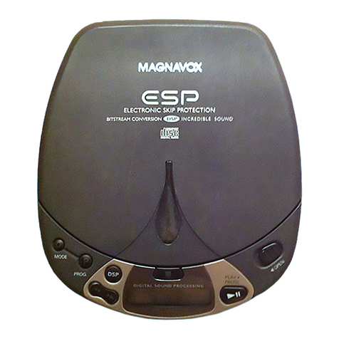
  9. Magnavox CDB472 User manual

Magnavox CDB472 User manual

Other Magnavox CD Player manuals

Magnavox AZ 7266 User manual

Magnavox

Magnavox AZ 7266 User manual

Magnavox AZ1307 - Portable Radio Cass Rec User manual

Magnavox

Magnavox AZ1307 - Portable Radio Cass Rec User manual

Magnavox AZ 7363C User manual

Magnavox

Magnavox AZ 7363C User manual

Magnavox AZ1407 User manual

Magnavox

Magnavox AZ1407 User manual

Magnavox MCS225 User manual

Magnavox

Magnavox MCS225 User manual

Magnavox Magnavox CD1450 User manual

Magnavox

Magnavox Magnavox CD1450 User manual

Magnavox AZ 8068 User manual

Magnavox

Magnavox AZ 8068 User manual

Magnavox AZ7261/05 User manual

Magnavox

Magnavox AZ7261/05 User manual

Magnavox AZ 7383 User manual

Magnavox

Magnavox AZ 7383 User manual

Magnavox AZ6820 - Portable Radio Cass Rec User manual

Magnavox

Magnavox AZ6820 - Portable Radio Cass Rec User manual

Magnavox CDC745 User manual

Magnavox

Magnavox CDC745 User manual

Magnavox AZ6840 - Cd Portable User manual

Magnavox

Magnavox AZ6840 - Cd Portable User manual

Magnavox AZ1100 - Single Deck User manual

Magnavox

Magnavox AZ1100 - Single Deck User manual

Magnavox AZ7461 - Portable Radio Cass Rec Assembly instructions

Magnavox

Magnavox AZ7461 - Portable Radio Cass Rec Assembly instructions

Magnavox AZ7275 - Cd Personal User manual

Magnavox

Magnavox AZ7275 - Cd Personal User manual

Magnavox CDB650 User manual

Magnavox

Magnavox CDB650 User manual

Magnavox AZ1100 - Single Deck User manual

Magnavox

Magnavox AZ1100 - Single Deck User manual

Magnavox MAGNAVOX MPC220SL User manual

Magnavox

Magnavox MAGNAVOX MPC220SL User manual

Magnavox MPC500 User manual

Magnavox

Magnavox MPC500 User manual

Magnavox AZ 7275 User manual

Magnavox

Magnavox AZ 7275 User manual

Magnavox MPC421 Owner's manual

Magnavox

Magnavox MPC421 Owner's manual

Magnavox AZ2750 User manual

Magnavox

Magnavox AZ2750 User manual

Magnavox MPC22017 - Portable Cd Player Operating manual

Magnavox

Magnavox MPC22017 - Portable Cd Player Operating manual

Magnavox AZ 7461 User manual

Magnavox

Magnavox AZ 7461 User manual

Popular CD Player manuals by other brands

Arcam CD23 Handbook

Arcam

Arcam CD23 Handbook

Sanyo MCD-Z1F Service manual

Sanyo

Sanyo MCD-Z1F Service manual

JVC RC-ST3SL instructions

JVC

JVC RC-ST3SL instructions

Technics SL-P9066 operating instructions

Technics

Technics SL-P9066 operating instructions

Marantz HD-CD1 quick start guide

Marantz

Marantz HD-CD1 quick start guide

Sony DVP-FX850 Service manual

Sony

Sony DVP-FX850 Service manual

Philips AZ1140 Instrukcja obs?ugi

Philips

Philips AZ1140 Instrukcja obs?ugi

Alpine 7909 owner's manual

Alpine

Alpine 7909 owner's manual

JVC CH-X350 instructions

JVC

JVC CH-X350 instructions

RCA RP-7923 instruction manual

RCA

RCA RP-7923 instruction manual

Pioneer DEH-P3550MP XM Operation manual

Pioneer

Pioneer DEH-P3550MP XM Operation manual

Philips Shockproof AX2102 brochure

Philips

Philips Shockproof AX2102 brochure

Philips CD582 user manual

Philips

Philips CD582 user manual

Philips AZ 6821 operating manual

Philips

Philips AZ 6821 operating manual

Lasonic MSU-2020 user manual

Lasonic

Lasonic MSU-2020 user manual

Denon DCD-1420 Service manual

Denon

Denon DCD-1420 Service manual

Panasonic SJ-MR100 operating instructions

Panasonic

Panasonic SJ-MR100 operating instructions

Onkyo DX-7210 instruction manual

Onkyo

Onkyo DX-7210 instruction manual

manuals.online logo
manuals.online logoBrands
  • About & Mission
  • Contact us
  • Privacy Policy
  • Terms and Conditions

Copyright 2025 Manuals.Online. All Rights Reserved.

(
(_
Manual No. 5373
CONSUMER
ELECTRONICS
CORP
A North American PHILIPS Company
Magnavox Model: CDB472
Chassis CD4
72/11R
Product Services
Technical Publications Dept.
P.O.
Box 555, Old Andrew
Johnson
Hwy.
Jefferson City,
TN
37760 - - - ---- -
--=
-----
--
-
------
--
For replacement purposes the remote control
is
available undercode number4822
218
20684
-------
-
For repair
of
the CD mechanism refer
to
Service
Manual CDM·21 version 0500.
erviceManual
When ordering replacementparts change
4122
to
4H
and
5322
to
5H
CONTENTS
Explanation
of
subdivision and table
of
contents per
page
2 Controls and technical specifications
3 Servicing hints
4 Measurements and adjustments
5 Exploded vieuws and parts lists
of
mechanical
components
6 Block diagram, circuit diagrams,
PCB
data, parts lists
of
electrical components and wiring diagram
7 Remote Control
8 Changes
9 Additional information
Safety regulations require that the set
be
restored
to
its original
condition and that parts which are identical with those specified
be
used.
(ru
□
~@
IIIIGffllLAUDIO
Copyright november 1987 N.A.P. Consumer Electronics Corp. Magnavox -Knoxville, Tennessee 37919
Subject
to
modification
4822 725 50835 cs 12 212
1-1
1.
EXPLANATION
ON
THE
LAYOUT
OF
THE
DOCUMENTATION
The
documentation consists
of
chapters.
The
number
of
the
chapter
is
indicated
by
the
first
digit
of
the
page number.
The
second digit
of
the
page number
is
the
sequence
numbering.
If
modifications
or
supplements require
new
supplementary
or
replacement pages,
the
page number
is extended with a third part:
A
digit
behind
the
page number indicates
that
it
concerns
a supplementary page.
A replacement page is indicated by a letter behind
the
page
number.
TABLE
OF
CONTENTS
PER
PAGE
Chapter
Page
Contents
Example
3-6
3-6-1
3-6-a
1 1-1 Explanation
of
the subdivision
of
the
documentation
Table
of
contents
per
page
2
3
4
5
2-1
2-2
3-1
3-2
4-1
4-2
4-3
4-4
4-5
4-6
4-7
4-8
5-1
Controls
Technical specification
Servicing hints
Disassembly
of
top
cover
Servicing
of
front
panel
Servicing
of
tray
mechanism
Disassembly
of
CDM
Servicing
of
servo +
decoder
panel
Replacement
of
transformer fuse
Electrical measurements and adjustments
General checkpoints
General checkpoints
Detailed measuring method
Exploded view tray mechanism
Partslist
of
mechanical components
is page 6
of
chapter 3
is a supplementary page behind page
3-6
is
the
replacement page
of
page 3-6
(so page 3-6 can
be
removed from
the documentation).
6 5-2
6-1
6-2
6-3
6-4
6-5
6-6
6-7
6-8
6-9
6-10
6-11
Exploded
view
of
cabinet+
parts list
of
cabinet components
Block
diagram
CS
11
944
GB
Wiring diagram
Circuit diagram
of
the
servo
Circuit diagram
of
decoder 1
Drawing
of
the main panel
Drawing
of
the main panel
Circuitdiagram
of
decoder 2
Circuit diagram
of
the
power
supply
Drawing
of
the
control
and
display
panel
and
its
circuit diagram
Electrical partslist
Partslist lead-less components
..
C
(
(
(
(
1
7 8
a b
2. CONTROLS
1 "ON/OFF" key: for switching the player on and off.
2 Display: functions as
on/off
indicator; gives information
about the number
of
tracks
on
the disc, the playing
time, the progress
of
play and particular functions
of
the player, and signals any faults occurring during
operation
or
programming.
3 Remote eye: for receiving the signals from the remote
control handset.
4
"<l<l
SEARCH
t>I>"
keys:
for
fast search
to
a particular
passage
(<l<l
backwards
t>!>
, forwards).
5 "PLAY/REPLAY" key: for starting play ("PLAY") and
returning
to
the beginning
of
a track ("REPLAY").
6 "STOP/CM" key:
for
stopping play during playback
("STOP") and for erasing a programme (CM = Clear
Memory).
7 "PHONES" socket:
for
the connection
of
a headphone
tor
listening
to
discs without using an amplifier.
8 "OPEN/CLOSE" key: for opening and closing the disc
tray.
2-1
2 3 4 5 6
9
10
11
12
13
14
C
42 452
0,2
9 'TRACK/TIME" key: for switching from track number
to
playing time indication and vice-versa.
10 "PROGRAM" key: for storing the track numbers
of
a
programme and producing the display
of
the
programme stored.
11
"PAUSE" key: for holding play at the start of a track
or
passage and for interrupting play.
12 "REPEAT" key: for repeating a disc
or
a programme.
13 " Kl INDEX
t>t
" keys: for indicating the index number
you want
to
begin with ( Kl " from index number
99
to
index number
01
and"
t>t
from index number
01
to
index number 99); also for returning to a previous
index number
or
moving on
to
a later one during play.
14 "PREVIOUS/NEXT' keys:
for
indicating the track
number you want
to
begin with, and selecting track
numbers when compiling a programme (
<J
from high
to
low and
I>
from
low
to
high); also for returning
to
a
previous track number or moving on
to
a later one
during play.
a.
Out
for
the signal output cable
to
the amplifier.
b.
RCS
in/out:
for
a separate receiver for the signals
from the remote control handset.
c. Connections for the mains lead.
CS
11
945
t:3B
2-2
TECHNICAL SPECIFICATION
• System
• Malnsvoltages
• Mains frequencies
•
Power
consumption
• Frequency range
• Output voltage
• Output impedance
•
S/N
ratio
• Chanell separation
SERVICE AIDS
Audio
test
disc
Disc without
errors+
disc with DO errors,
: Compact Disc Digital
Audio system
: 110 V,
127
V,
220
V,
240
V
±
10%
(to be changed by
transformer connections)
: 50-60
Hz
(no adaption
required)
:
14W
: 2 Hz +
20
kHz ± 0,05
dB
: max. 2 V
,mJ;;;,,
10 kOhms
: 200 Ohms
:
;;;,,96
dB
: ;.,.93 dB
4822
397
30085
black
spots
and
fingerprints
Torx
screwdrivers 4822 397 30096
4822
395
50145
4822
395
50132
4822
395
30204
4822 321 21284
4822
322
40066
4822 267 50676
5322 130 32182
Set
(straight)
Set
(square)
13th
order filter
Service cable (4-pole)
Service cable (14-pole)
Service connector (14-pole)
Green LED CQYG II
cs
12213
• Total harmonic
distortion
• Intermodulation
distortion
• Remote control
• De-emphasis
• Dimensions wxhxd
• Weight
• Headphone
:
...;0,003%
(-90 dB}
:
os;;;0,003%
(-90 dB)
: Cinch
bus
for
RC5
system
: 0
or
15/50
µs (switched
by the subcode
on
the disc)
: 420 x
86
x 300
mm
(tray closed)
420 x 86 x 425
mm
(trayopened)
: approx. 3
kg
-Output voltage : max.
5.6
Vrms
-Output impedance : 150 0
-Load Impedance range: 8 O - 2
k.O
-Output power :
30
mW
at
32
n
C
C
(
(
3-1
3. SERVICING HINTS
J.
ESD~
In
the
set
chip components have been applied.
Alie
ICs
and
many
other
semi-conductors are susceptible
to
electrostatic discharges
(ES
□).
For
disassembly and assembly
of
chip
components see
the
figure below.
For
measurements and adjustments
it
is
possible
to
position
the
working mechanism
outside
the
set.
Careless handling during
repair
can
reduce
life
drastically.
To
do
this
work
the
following service aids are available:
When
repairing,
make
sure
that
you
are connected
with
the
same potential
as
the
mass
of
the
set
via a
wrist
wrap
with
resistance.
-Service flat cable (14-pole) 4822
322
40066
-Service
connector
(14-pole) 4822 267 50676
These
two
items should
be
used
to
assemble
an
extension calbe between
connector
11
and
the
flex
cable
of
the
CDM-2 unit.
Keep
components and
tools
also
at
this potential.
The
disc
should always
rest
properly
on
the
turntable.
To
achieve this a
disc
hold-down
has
been mounted in
the
cover. Remark:
The
service cable should be assembled
as
follows (see drawing
MDA
00311).
When
the
cover
has
to
be taken
from
the
set
for
repair, a
separate hold
down
should
be
used.
The
14-pole connector
should
be soldered
as
Indicated In
the
drawing. Please remove
the
blue
tape
of
the
rear
of
the
service
flat
cable-end
which
has
to
be connected
to
connector
11.
Switch
SK2
has
to
be activated.
The
set
can
be
used normally.
GENERAL
CfilP
SO
LO
ER
COMPONENT SOLD
ER
,)'J l
Ql'c~o;:eRTRACK
GLUE
SERVICE PACKAGE
DISMOUNTING
VACUUM PISTON
SOLDERING
~2
IRON~
o g. WELLER
~~~=~~
SOLOEA
TIP
PT-H7
OR
SOLOERING
IRON~
SOLDER
WICK
4s22
32~
400•2q...,..__,.....I
l
COM FLEX-CABLE
4822 267 50676
SOLDER JOINT
4822
322
40066 MDA.00311
T19-730
MOUNTING
e.g. A
PAIR
OF
TWEEZERS
A
~
SOLDER
00.5-0
.8
mm
PRESSURE
♦
A
8
e.g. A
P~EZERS
B
HEATING~
HEATING
' II
I i
SOLDERING TIME
< 3
3ec/side
SOLDER
0O
.S • 0.8
mm
SOLOEAING IRON
SOLDER
WICK~
CLEANING
PRECAUTIONS
C
EXAMPLES
SOLDERING
IRON
~
~
SOLDERING
IRON
~
~
(?,$,
~~
Fig. 1
21 012c12
CS
11
947G
3-2 ·
DISASSEMBLY OFTOP COVER
-Remove
the
4 screws
out
of
side walls
of
top cover.
-Take
top
cover
from
set.
SERVICING OF THE FRONT PANEL
Disassembly
of
front panel
-Remove
top
cover.
-Remove the 3 fixing screws
at
upperside
of
fornt panel.
-Nowthe
front
panel can
be
taken off.
-Ensure during mounting that the 3 bosses
of
the set
frame engage with
the
appropriate holes
of
the
frontpanel.
Disassembly
of
control+
display panel
-The control and display PCB can be detached by
removing the 7 screws 3Mx16
at
the bottom
of
the
display panel.
-Then the control + display panel can
be
taken
out
of
the front.
-When mounting, make sure that the 3 bosses on the
front slip
into
the appropriate holes in the PCB.
SERVICING OF THE TRAY MECHANISM
-Demounting the tray mechanism.
-Remove the
top
cover.
-Remove the front.
-Push the tray
out
of
the mechanism.
-Remove
the
screw from the bottom
of
the set.
-Undo
the
3 screws with which the loading has been
mounted into the set.
Two
screws are situated in front
and one in the centre
at
the rear.
-Lift the tray mechanism a little and undothe flexible
PCB
from
the connector
by
lifting the upper part
of
the
connector and taking the flexible PCB
out
Short circuit
the connections
by
means
of
a paperclip.
-Undo
the
2 stocko connectors.
-Now take
the
tray mechanism
out
of
the
set.
CS
11
948
GB
DEMOUNTING THE CDM
-Remove the complete disk hold-down.
-Turn
the
loading upside down.
-Support
the
COM.
-Loosen the 2 screws on the metal bracket with which
the
COM
is
suspended.
-The CDM can
now
be
removed.
-
For
servicing the COM see Service Manual
CDM2/0500.
-Mounting is done in reverse order.
SERVICING THE
SERVO+
DECODER PANEL
-Remove
top
cover.
-Remove the
front
panel.
-Remove the tray mechanism.
-Remove the screw with which the chassis part is fixed.
-Remove the screw in the rear with which the CINCH
sockets are fixed.
-Remove
the
2 screws on the PCB.
-Remove
the
screws from the transformer.
-The PCB now can
be
taken out.
-Mounting
is
done in reverse order.
REPLACEMENT OF TRANSFORMER FUSE
-
For
replacing the transformer fuse the transformer
must
be
desoldered from the PCB.
(
C
(
(
(
C
4. ELECTRICAL MEASUREMENTS
AND
ADJUSTMENTS
HINTS
Test
disc
It
is
important
to
treat
the
test
discs with great care.
The
disorders
on
the
discs (black spots, fingerprints, etc.) are
exclusive and unambiguously positioned. Damage
may
cause additional drop-outs, etc. rendering
the
intentional
errors
no
longerexclusive. In
that
case
it
will
no
longer
be possible
to
check
e.g.
the
good working
of
the
track
detectors.
Measurements
on
op-amps
In
the
electronic circuit op-amps have been used
frequently. Some
of
the
applications are amplifiers,
filters, inverters and buffers.
In
those
cases where in
one
way
or
the other, feedback
has been applied
the
voltage difference
at
the
differential
inputs converges
to
zero.
This
applies
to
both DC and
AC signals.
The
cause can
be
traced
to
the properties
of
an
ideal
op-amp
(Z1=
oo,
G =
oo,
20 =0).
If
one
input
of
an
op-amp
is
directly connected
to
ground
it
will be
virtually impossible
to
measure
at
the
inverting and
the
non-inverting inputs. In such cases
only
the
output
signal
will
be
measurable.
That
is
why
in
most
cases
the
AC voltages
at
the
inputs
will
not
be
given. The DC voltages
at
the
inputsare equal.
Stimulation with
"0"
and
"1"
During troubleshooting sometimes certain points should
be
connected
to
ground
or
supply voltage.
As
a result
certain circuit
can
be
brought
in a desired
state
thus
shortening
the
diagnosis time. In a number
of
cases
the
related points are outputs
of
op-amps. These outputs are
short-circuit-resistant, i.e. they can
be
brought
to
"O"
or
ground
without
problems.
The output
of
an
op-amp, however, should never be
connected directly
to
the
power
supply voltage.
Measurements on microprocessors
Inputs and outputs
of
microprocessors should never
be
connected directly
to
the
power
supply voltage.
The
inputs and outputs should only
be
brought
to
"O"
or
ground
if
this
is staed explicity.
Measurements with an oscilloscope
During measurements
with
an oscilloscope
it
is
recommended
to
measure with a 1:
10
test
probe, since a
1:10 probe has a considerably smaller input capacitance
than a 1
:1
probe.
Selection
of
ground potential
It
is
very
important
to
select a
ground
point
that
is
as
close
as
possible
to
the
test
point.
Conditions for injection
-Injection.of le\lels
0r
si_gnals
from an
extemal
source
should
never
take
place'if
ihe
related circuit has
no
supply
voltage.
T<he
,injected ,levels
or
signals·Shol!lld never
be
greater
than
the
supply
voltage
of
the
·r.elated circuit.
4-1
GENERAL CHECKPOINTS
In
the
detalled measuring method below a number
of
general conditioAs, required
for
a properly functioning
set, will
not
be
mentioned. Before
the
detailed measuring
method is started, these general points should
first
be
checked.
a. Ensure
that
disc and objective are clean (remove dust,
fingerprints, etc.)
and
work
with
undamaged discs.
b. Check
if
all supply voltages are present and
if
they
have
the
correct values.
c. Check
the
good
working
of
the
CD
mechanism by
means
of
the
servicing programme.
Indication
of
test
points
In the drawings
of
the
diagrams and
the
panel~e
test
points have been indicated
by
a number(e.g. '(.3/')
to
which the measuring method refers. In
the
measuring
method below,
the
symbol
(◊J
has been omitted
for
the
testpoints indicated.
Initiation
of
the
servicing programme
of
the
µP
-Service position "0"
Press
the
STOP/CM, NEXT and PAUSE keys. Keep
these three keys depressed while switching
on
the
mains voltage. This is
the
1
st
standby position.
The
number
of
the
internal ROM program
of
the
µP (e.g.
P101) appears
on
the display.
The
"TRACK" Led lights
up
as
well. In
this
position
the
radial arm
of
the COM
can be driven Inwards (with SEARCH >
>)
and
outwards
(with < < SEARCH)
with
minimum torque.
When one
of
these search keys
is
actuated, laser
control and focus control become active
as
well.
If
a
disc is
put
on
the
turntable,
the
working
of
the
focus
control can already
be
observed in this position. (It
the
arm moves outwards and inwards, you can hear the
optical pick-up unit
jump
across
the
tracks).
Attention:
After
one
of
these keys (SEARCH >
>,
<<
SEARCH) is pressed, the laser remains controlled
up
to
service position 3. Avoid, therefore, direct
exposure
to
the
laser beam in service positions
0,
1
and 2).
-Service position
"1"
From service position
"O"
the
player can
be
brought
into service position "1"
by
pressing
the
"NEXr
key.
The
indication "0001" appears
on
the
display. In
this
position
the
focus
start
procedure is repeated
over
and
over
again. The lasercontrol
is
active.
However,
this
start procedure does
not
release
the
focus,control. So
we
cannot
ascertain
that
the focal
point
is
found. This position
is
very suitable, however,
tor
measurements
of
the
focus circuit.
In service positions 1 and 2
the
arm
with
the
rafoc
unit can be moved inwards and
outwards
with the
SEARCH >> key and
the
< < SEARCH key
respectively. In this
way
the
free
movement
of
the
arm under
the
disc
can
be
checked.
CS
11
949 GB
4-2
-service
posHion
"2"
To
be
attained
by
pressing
the
"NEXr
key
after
service position
"1"
is
reached.
The
Indication "0002"
appears
on
the
display.
Make
sure
that
the
rafoc
unit
is within
the
reach
of
the
disc.
If
a
disc
is
put
on
the
turntable in
this
position,
the
working
of
the
decoder
(MC signal) and
the
turntable
motor
control
can
be
checked (turntable
motor
is running
at
the
right
speed).
Laser
control, focus control and turntable
motor
control
are
active. This position is very suitable
for
measurements
of
the
turntable
motor
control.
If
the
HF-signal
Is
not
well
coded
or
if
no
disc
is
present,
the
turntable
motor
will
start
rotating
at
maximum
speed.
-Service position
"3"
To
be
attained
by
pressing
the
"NExr
key
after
service position "2"
is
reached. The indication "0003"
appears briefly
on
the
display.
Then
the
normal
standby display
is
shown.
The
set
is
now
in the 2
nd
standby position.
All
keys have
their
original function
again.
In
case
of
deviations
an
extensive
error
indication
takes
place
via
the
display.
-
If
the µP
observes
a system
error,
a system
error
Indication will
appear
on
the
display: Er 01
to
Er 08.
-
If
the
µP
observes
an
operating error,
an
operating
error
indication will
appear
on
the display
for
1.5 sec.:
Er
30
to
Er
37
and
Er 60
to
Er
61.
For
an
explanation
of
the
error
indications: see
Error
table.
The
service
program
can
be
abandoned
by
turning
the
mains
switch
(POWER ON/OFF)
off
and
on
again
(Hardware reset).
CS
11
950
1GB
Specification measurement
CO
PLAYER
"'-----1
FILTER
t-------:R="
Fig. 4
!VN
AND
DISTORTION
METER
•-G·
SOU
NC
TECl!NOLOGV
ST
1700B
30
'59
A12
To
measure
the
specification
use
can be made
of
audio
test
disc
4822
397
30095.
Use 13th
order
filter
4822
395 30204
to
measure (see
Fig.4):
-Total harmonic distortion (THD)
-Intermodulation distortion
-Signal-to-noise ratio (S/N)
Continuous burning of the laser
See initiation
of
the
Servicing
programm
Service position
"O"
Note: Danger
Invisible
laser
radiation.
Avoid
direct
exposure
to
beam.
Check of the laser supply
The
laser
and,
the
laser
supply
in IC6525
plus
the
monitor
diode
form
a feedback system.
A
defect
in
the
laser
supply
can result
in
the
destruction
of
the
laser.
If, in
that
case,
the
laser
(=
complete
CDM2
unit) is
replaced, the
new
laser
will also become defective.
However,
it
is impossible
to
check and
repair
a feedback
system
if
a
link
Is missing. The
laser
supply
can be
checked
with
the
circuit
below.
The
green
LED replaces
the laser,
the
voltage
across
the
18 Ohm resistor is feed
back
as
monitor
voltage, the
33
Ohm
resistor
and the
switch
serve
to
draw
more
current
from
the
laser
supply
.
..---------<>
to
LO
.__
_____
---a
to ..L
Fig. 5
LED GREEN e.g. COY 94 IV
CONNECTED
DIRECTLY
TO
PANEL
42
444
A12
5322 130 32182
The
above
circuit Is connected
to
the connector
on
the
main panel·via
an
extension cable instead
of
a
flex
print.
The normal
flex
print
is
not
suited
for
this
purpose
because
of
its
high
internal resistance.
Code
no.
extension cable 4822 322 40066
C
C
(
(
(
C
-Take
the
above flex print
out
of
connector
31
on
the
main panel.
-Connect
the
circuit via
the
extension cable
to
the
connector.
-Selectthe playmode
by
grounding Si (pin
20
of
IC6525).
Note: Si "' 0, start Initialisation low, is
the
play mode.
-Measure
the
voltage LO (Laser Out)
at
test
point
9.
SK
open: 1,8V
,s;;
LO
,s;;
2,3 V
170
Mv
,s;;
LM
.,s;;
220 mV
The
green LED emits little light.
SK
closed: 1,8 V
,,;:;
LO
,s;;
2,3 V
170
Mv
,s;;
LM
.,r,;;
220
mV
The
green LED emits little light.
-During
the
change
over
from
SK
closed
to
SK
open,
the
LED will
emit
more light
for
a
short
moment.
-
The
control
sees
to
It
that
the
same
amount
of
current
flows through
the
LED
when
SK
is
open
and
when
SK
Is closed.
At
Si=
1, in
the
STAND-BY state,
LO=
0 V ± 0,2 V.
Repair
procedure
Since laser,
monitor
diode
and
photodiodes are very
sensitive
to
static charges,
care
should
be
taken
that
during measurements
and
adjustments
the
aids
and
yourself have a potential
that
is equal to that of
the
CD
mechanism.
Attention: When exchanging
the
CDM2
unit,
the
laser
output
potentiometer3528 should be placed in
mechanical mid-position
to
avoid damage
to
the
laser.
Adjusting the laser current.
Coarse adjustment
-Place potentiometer 3528 approximately in
mid-position.
-Put
test
disc
5
on
the
turntable.
-Bring
the
player In service position 3, position PLAY.
-
The
focusing
motor
can
now
start
focusing and when
it
has found
the
focal
point
index
01
will appear
on
the
display.
-
If
this does
not
happen,
turn
potentiometer 3528
clockwise
or
anti-clockwise a little and press
the
play
button again
Here after
the
fine adjustment
of
the
laser current
has
to
be
carried out.
Fine adjustment
-Play
track
1
of
the
test
disc
5.
-
Adjust
potentiometer
for
a voltage across 3508
test
point
1 and 2
of
50 mV ± 5 mV.
Adjustment of the focus
off-set
Coarse adjustment
-
Adjust
the
focussing
motor
to
the
eye
tor
a horizontal
position
by
means
of
potentiometer3517
-Here after
the
fine adjustment
of
the focus
off-set
has
to
be carried out.
Fine adjustment
-Bring
the
player in service position
2.
-Adjust potentiometer
351-7
for
a voltage
across
2545
(test point 27)
of
400
mV
±
40
mV.
Note: Notice that the CDM
is
in a horizontalposition.
4-3
Changing
the transformer connections
127V~
2
J
UNITS
SOLD
IN
US.A.
CANNOT
BE
CHANGED
AS THEY
HAVE
A DEDICATED TRANSFORMER
6
22ov~
24DV~
42
492
A12
Fig. 6
If
the set should be connected
to
a mains voltage
that
deviates from the voltage mentioned
on
the
type plate,
the transformer connections should
be
changed,
as
indicated
in
Fig.
6.
DETAILED MEASURING METHOD
I.
µP
IC6551
• Servicing program
For initiation
of
the servicing program see: General
checkpoint: Initiation
of
the
service program.
• Reset
(pin
1)
When
the
supply voltage is switched on, a positive
pulse should be present.
• X-tal out (pin 39;
test
point
13)
The frequency
of
this signal should
be
6 MHz.
• MSTP (pin 26;
test
point 78)
When, after
RD
"high",
the
MSTP is "high"
for
a
short
moment(
> 0.2 sec.), the turntable
motor
control will
be switched on.
The turntable motor is controlled
by
the
MC-signal
{test point 12).
To
check MC, see: "Decoder A IC".
To
check the
turntable motor control see CDM2 Service Manual
"Checking
of
the
motor control".
•
BO
(pin 11;
test
point
36)
B1
(pin 10; test point 34)
B2 (pin 9 ;
test
point
33)
B3 (pin 8 ;
test
point
32)
CS
11
951
GB
4-4
With
the
BO
+ B3
signals
•
The
radial
control
is switched on.
•
The
level
on
the
DAG
output
is
controlled.
-
In
the
SEARCH
mode,
there
should
be activity
on
all 4
test
points.
-
In
the
following
positions
the signals
BO
+
B3
are
stable:
STOP
PLAY Service Service
signal
pas.
0,1,2
pos.
3
BO
"low" "high" "low" "high"
81 "high" "high" "high" "high"
82
"high" "high" "high" "high"
83
"low" "low" "low"
"low·
•
TL
(pin 34;
test
point
16)
-
The
TL
signal (Track Lost) Is
used
to
tell
the
µP
that
track
loss
threatens. The µP then can give
correction
signals
with
BO
+
83.
-In the "SEARCH"
mode,
or
when
the
player
is bumped
against,
there
are
pulses
on
test
point
16.
• REdig (pin 7;
test
point
37)
The
REdig signal
(=
Radial
Error
Digital
"'
radial
deviation)
Is
used
to
determine
the
place
of
the
arm
relative
to
the
track
and
to
check/corect
in case
of
track
jumping
or
bumping against
the
player.
In
servicing
position
3
or
In
the
PLAY mode, a
square
wave
should
be
present
on
test
point
37.
Because
of
frequency
variations,
this
square
wave
is
hard
to
trigger.
• DODS (pin 5;
test
point
19)
The
DODS
signal(=
Drop
Out Detector Suppression)
avoids
that
Drop-Out
signals influence the arm
control
during
track
Jumping.
Position
of
player
D00S
signal
POWER
Servicing
ON
pos.
3
"low" "high"
PLAY
"high"
SEARCH
7-r'U
MDA
.00364
T12
-638
11.
PHOTODJODE
SIGNAL
PROCESSOR IC6525
• SC (pin 25)
SC(=
Start Capacitor)
High Ohmic measurement
Position
of
player
SC
(pin 25)
POWER
ON
-4
V
PLAY
+5V
Servicing pos. 1
+5
V
CS
11 952 GB
• SI (pin 20;
test
point
21)
LO
(pin 17;
test
point 9,
9-',
98)
-With
the
Si signal
(=
Start
Initialization)
the
laser
supply,
among
other
things, is switched on.
When the Si signal is "low",
the
LO
signal
(=
Laser
Out)
should
be "high".
Via
the
LM
signal
(=
Laser
Monitor)
the
power
supply
for
the
laser
diode
is controlled.
Position
of
POWER Servicing PLAY
player
ON
pos.
1
*)
Si signal "high" "low" "low"
LO signal "low" "high" "high"
• LM (pin 16:
test
point
11)
to
check
LM
See general checkpoints 'check
of
the
laser supply'
• To
check
the
laser
supply, see General checkpoints
"Check
of
the
Laser
Supply".
• To
check
the
focus offset, see Generalcheckpoints
"Adjustment
of
the Focus Offet".
*)
To
ensure that
the
player
stays in servicing position
1,
there should
be
a
disc
on
the
turntable.
• FE pin (pin
5;
test
point 26)
-The FE signal
(=
Focus Error)
is
used
to
drive the
focusing
u.!![t.
When the
Si
signal
goes
to
"high", the focal
point
will
be searched for.
When the player is
brought
into
servicing position 1
without disc,
the
objective will search
for
the focal point.
At
test
point
26
the FE signal varies between
+2 V and
-1,5
V.
•
RD
signal (pin
21;
test
point 24)
HIGH-OHMIC MEASUREMENT
The
RD signal
(=
Ready) will
go
high
when
the
starting
procedure
of
IC6525
has
been completed.
POSIT10N
PU,
VEA
~
ON
SER\/ICE
P05ITlON
I
ADSIGNAI.
POWER
ON
• 01 (pin 9 ;
test
point 4)
02
(pin 10;
test
point 6)
03
(pin 8 ;
test
point
7)
D4
(pin 7 ;
test
point
8)
-The signals
D1
+D4
are
the
error
signals
from
the
photodetector circuits.
-When in servicing position 2
the
disc
is moved,
the
focusing
unit
should keep in track.
When
the
disc
is moving, there should be a changing
signal
on
test
points
4, 6, 7 and
8.
C
(