manuals.online logo
Brands
  1. Home
  2. •
  3. Brands
  4. •
  5. Sony
  6. •
  7. CD Player
  8. •
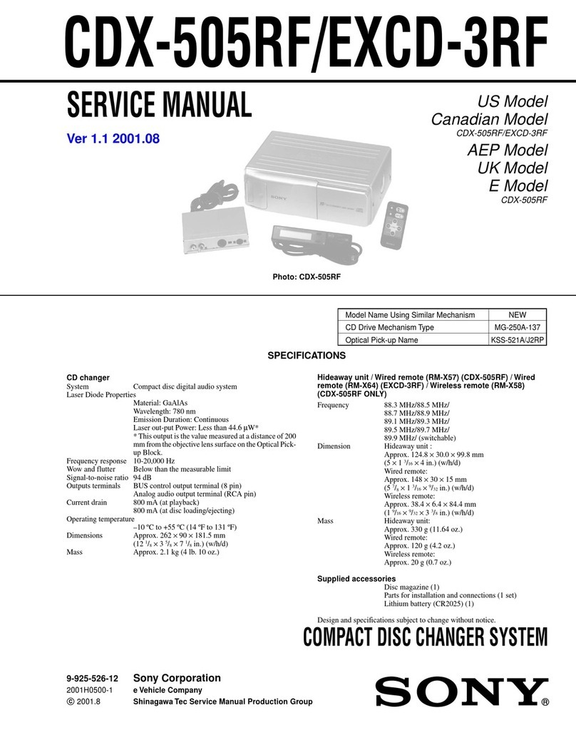
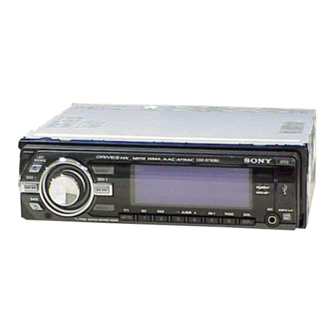
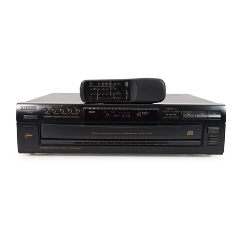
  9. Sony CDX-R88 User manual

Sony CDX-R88 User manual

This manual suits for next models

1

Other Sony CD Player manuals

Sony CD Walkman D-CJ500 User manual

Sony

Sony CD Walkman D-CJ500 User manual

Sony CFD G505 - Xplod Boombox User manual

Sony

Sony CFD G505 - Xplod Boombox User manual

Sony Discman D-335 User manual

Sony

Sony Discman D-335 User manual

Sony SCD-CE595 User manual

Sony

Sony SCD-CE595 User manual

Sony CDX-GT07 - Fm/am Compact Disc Player User manual

Sony

Sony CDX-GT07 - Fm/am Compact Disc Player User manual

Sony CD Walkman D-E551 User manual

Sony

Sony CD Walkman D-E551 User manual

Sony KDX-565MXRF User manual

Sony

Sony KDX-565MXRF User manual

Sony D-NE20 - Atrac Cd Walkman User manual

Sony

Sony D-NE20 - Atrac Cd Walkman User manual

Sony CDX-GT550UI  (CDX-GT550UI) User manual

Sony

Sony CDX-GT550UI (CDX-GT550UI) User manual

Sony DVP-FX970 User manual

Sony

Sony DVP-FX970 User manual

Sony CDX-GT350 User manual

Sony

Sony CDX-GT350 User manual

Sony D-FJ401 - Discman User manual

Sony

Sony D-FJ401 - Discman User manual

Sony DVP-FX930 User manual

Sony

Sony DVP-FX930 User manual

Sony SCD-XE600 User manual

Sony

Sony SCD-XE600 User manual

Sony CD Walkman D-EJ611 User manual

Sony

Sony CD Walkman D-EJ611 User manual

Sony SCD-CE595 User manual

Sony

Sony SCD-CE595 User manual

Sony CDX-S2010 - Fm/am Compact Disc Player User manual

Sony

Sony CDX-S2010 - Fm/am Compact Disc Player User manual

Sony WALKMAN D-CJ01 User manual

Sony

Sony WALKMAN D-CJ01 User manual

Sony CDX-G1200U User manual

Sony

Sony CDX-G1200U User manual

Sony CDP-CX70ES - Es 200 Disc Cd Player User manual

Sony

Sony CDP-CX70ES - Es 200 Disc Cd Player User manual

Sony Walkman D-FJ211 User manual

Sony

Sony Walkman D-FJ211 User manual

Sony Walkman D-EJ001 User manual

Sony

Sony Walkman D-EJ001 User manual

Sony CDX-656 - Compact Disc Changer System User manual

Sony

Sony CDX-656 - Compact Disc Changer System User manual

Sony D-NE710 - ATRAC3/MP3 CD Walkman Portable Disc... User manual

Sony

Sony D-NE710 - ATRAC3/MP3 CD Walkman Portable Disc... User manual

Popular CD Player manuals by other brands

Arcam CD23 Handbook

Arcam

Arcam CD23 Handbook

Sanyo MCD-Z1F Service manual

Sanyo

Sanyo MCD-Z1F Service manual

JVC RC-ST3SL instructions

JVC

JVC RC-ST3SL instructions

Technics SL-P9066 operating instructions

Technics

Technics SL-P9066 operating instructions

Marantz HD-CD1 quick start guide

Marantz

Marantz HD-CD1 quick start guide

Philips AZ1140 Instrukcja obs?ugi

Philips

Philips AZ1140 Instrukcja obs?ugi

Alpine 7909 owner's manual

Alpine

Alpine 7909 owner's manual

JVC CH-X350 instructions

JVC

JVC CH-X350 instructions

RCA RP-7923 instruction manual

RCA

RCA RP-7923 instruction manual

Pioneer DEH-P3550MP XM Operation manual

Pioneer

Pioneer DEH-P3550MP XM Operation manual

Philips Shockproof AX2102 brochure

Philips

Philips Shockproof AX2102 brochure

Philips CD582 user manual

Philips

Philips CD582 user manual

Philips AZ 6821 operating manual

Philips

Philips AZ 6821 operating manual

Lasonic MSU-2020 user manual

Lasonic

Lasonic MSU-2020 user manual

Denon DCD-1420 Service manual

Denon

Denon DCD-1420 Service manual

Panasonic SJ-MR100 operating instructions

Panasonic

Panasonic SJ-MR100 operating instructions

Onkyo DX-7210 instruction manual

Onkyo

Onkyo DX-7210 instruction manual

Cambridge Audio SONATA CD30 manual 

Cambridge Audio

Cambridge Audio SONATA CD30 manual 

manuals.online logo
manuals.online logoBrands
  • About & Mission
  • Contact us
  • Privacy Policy
  • Terms and Conditions

Copyright 2025 Manuals.Online. All Rights Reserved.

SERVICE
MANUAL
HIDE-AWAY
UNIT
SPECIFICATIONS
AUDIO
POWER
SPECIFICATIONS
POWER
OUTPUT
AND
TOTAL
HARMONIC
DISTORTION
11
watts
per
channel
minimum
continuous
average
power
into
4
ohms,
both
channels
driven
from
30-20,000
Hz
with
no
more
than
1%
total
harmonic
distortion.
OTHER
SPECIFICATIONS
Power
amplifier
section
(inside
of
the
hide-
away
unit)
Outputs
2
Line
outputs
Inputs
Auxiliary
inputs
Maximum
power
output
25
watts
per
channel
at
4
ohms
Bass
+8
dB
(100
kHz)
Treble
+8
dB
(10
kHz)
Tone
controls
CD
player
section
System
system
Laser
Diode
Properties
Material:
GaAlAs
Wavelength:
780
nm
Emission
Duration:
Continuous
Laser
output
power:
Less
than
44.6
p.W*
*This
output
is
the
value
measured
at
a
distance
of
about
200
mm
from
the
objective
lens
surface
on
the
Optical
Pick-up
Block.
MICROFILM
Compact
disc
digital
audio
US
Model
Canadian
Model
AEP
Model
E
Model
CDX-R88:
US
Model
CDX-R66:
Frequency
response
:
5-
20,000
Hz+3
dB
Harmonic
distortion
0.008%
(1
kHz)
Dynamic
range
90
dB
Signal
to
noise
ratio
85
dB
Wow
and
flutter
General
Below
measurable
limit
Power
requirements
Current
drain
12
V
DC
car
battery
(negative
ground)
800
mA
(CD
playback)
2
A
(during
disc
loading
or
eject)
Operating
temperature
Dimensions
Weight
—
10°C-50°C
(15°F
-
120°F)
CD
player:
Approx.
178
x
50
x
144
mm
(w/h/d)
(71%
x
2
x
5%
in.)
Hide-away
unit:
Approx.
178
x
30
x
180
mm
(w/h/d)
(71%
x
11516
x
714
in.)
including
projecting.
parts
and
controls
Approx.
2.5
kg
(5
Ib
8
oz)
incl.
hide-away
unit
—
Continued
on
page
2
—
FM/AM
COMPACT
DISC
PLAYER
SON
Y.
CDX-R88/R66
Tuner
section
(inside
of
the
hide-away
unit)
FM
tuner
section
AM
tuner
section
Tuning
range
{
87.9
—
107.9
MHz
{US,
Canadian
models}
87.5
—
108
MHz
{AEP,
E
models)
§31-
1,620
kHz
(at
9
KHz)
530
-
1,620
kHz
(at
10
kHz;
adjustable
with
the
model
only
for
E
model}
Antenna
terminal
FM/AM
external
antenna
connector
67
dB
(stereo)
intermediate
frequency
J
10.7
MHz
450
KHz
Pern
Usable
sensitivity
{|
11.2
dBf
(1.0
x.V/75
ohms)
Sensitivity
—
28
Vv
bs
|
at
50
dB
quieting
16.4
dBf
(1.8
.V/75
ohms)
Selectivity
75
dB
at
+400
kHz
—
Signal-to-noise
ratio
70-08
(monaural
55
dB
t
Harmonic
distortion
at
1
kHz
0.2%
(monaural)
0.3%
(stereo)
0.3%
Stereo
separation
40
dB
[
Frequency
response
|
20H2-
15,000
Hz
+3.dB
FEATURES
eA
DIN
sized
mobile
CD
player
and
a
hide-away
unit
in
which
FM/AM
tuner,
power
amplifier
ana
power
supply
section
are
combined.
¢
Fader-control
to
adjust
the
volume
of
the
front
and
rear
speaker
for
4-speaker
system.
¢
Auxiliary
inputs
to
connect
an
optional
cassette
car
stereo.
©
Quick
recovery
from
sound
skipping.
Even
if
strong
vibration
may
cause
sound
skipping,
the
player
can
relocate
the
point
where
the
play
was
interrupted.
¢Maximum
power
output
of
25
watts
per
channel.
CAUTION
Use
of
controls
or
adjustments
or
performance
of
procedures
other
than
those
specified
herein
may
result
in
hazardous
radiation
exposure.
SAFETY-RELATED
COMPONENT
WARNING!!
COMPONENTS
IDENTIFIED
BY
SHADING
AND
MARK
A
ON
THE
SCHEMATIC
DIAGRAMS
AND
IN
THE
PARTS
LIST
ARE
CRITICAL
TO
SAFE
OPERATION.
REPLACE
THESE
COMPONENTS
WITH
SONY
PARTS
WHOSE
PART
NUMBERS
APPEAR
AS
SHOWN
IN
THIS
MANUAL
OR
IN
SUPPLEMENTS
PUBLISHED
BY
SONY.
ATTENTION
AU
COMPOSANT
AYANT
RAPPORT
A
LA
SECURITE!
LES
COMPOSANTS
IDENTIFIES
PAR
UNE
TRAME
ET
UNE
MARQUE
A
SUR
LES
DIAGRAMMES
SCHE-
MATIQUES
ET
LA
LISTE
DES
PIECES
SONT
CRITIQUES
POUR
LA
SECURITE
DE
FONCTIONNEMENT.
NE
REM-
PLACER
CES
COMPOSANTS
QUE
PAR
DES
PIECES
SONY
DONT
LES
NUMEROS
SONT
DONNES
DANS
CE
MANUEL
OU
DANS
LES
SUPPLEMENTS
PUBLIES
PAR
SONY.
TABLE
OF
CONTENTS
Section
Title
Page
Specifications
.................00000.
1
POatures.
cic
cad
in
ke
oe
wok
he
ate
da
bed
te
e
2
Servicing
Note
............
0000
eee
3
Précautions’
+...
3-086
sce
ce
gm
es
3
Installation
and
Connections.
.............
4
Location
and
Function
of
Controls
.........
6
How
to
Set
the
Clock
..................
8
Memory
Preset
Tuning..................
9
1.
DISASSEMBLY
]-1.
Removal
...........000
cece
cues
10
2.
ELECTRICAL
ADJUSTMENTS
HIDE-AWAY
SECTION
................
15
FM
Discriminator
Alignment
...........
15
FM
Auto-scan
Stop
Level
Adjustment
.....
16
AM
Auto-scan
Stop
Level
Adjustment
.....
16
FM
Stereo
Separation
Adjustment
........
17
CD
PLAYER
SECTION
................
18
PLL
Free
Run
Frequency
Adjustment
.....
18
Focus
Offset
Adjustment
..............
19
Tracking
Offset
Adjustment
............
19
Tracking
Gain
Adjustment
(rough
adjustment)
..................
20
Focus
Gain
Adjustment
(rough
adjustment)
..................
21
Semiconductor
Lead
Layouts
.............
22
3.
DIAGRAMS
3-1.
Mounting
Diagram
—
Hide-away
Section—
.............
23
3-2.
Schematic
Diagram
—
Hide-away
Section—
.............
26
3-3.
Mounting
Diagram
—
CD
Player
Section—
.............
31
3-4.
Schematic
Diagram
—
CD
Player
Section—
..........,..
35
4.
EXPLODED
VIEWS
AND
PARTS
LIST
................,.4.
41
5.
ELECTRICAL
PARTS
LIST........-.
48
Trouble
Checks
.
2...
0600.04
cee
ee
56
SERVICING
NOTES
NOTES
ON
HANDLING
THE
OPTICAL
PICK-
UP
BLOCK
OR
BASE
UNIT
The
laser
diode
in
the
optical
pick-up
block
may
suffer
electrostatic
breakdown
because
of
the
poten-
tial
difference
generated
by
the
charged
electrostatic
load,
etc.
on
clothing
and
the
human
body.
During
repair,
pay
attention
to
electrostatic
break-
down
and
also
use
the
procedure
in
the
printed
matter
which
is
included
in
the
repair
parts.
The
flexible
board
is
easily
damaged
and
should
be
handled
with
care.
CDX-R88/R66__
Flexible
Circuit
Board
Repairing
1.
Keep
the
temperature
of
the
soldering
iron
at
270°
+
10°C
during
repairing.
You
can
maintain
the
temperature
of
the
soldering
iron
around
270°C
by
using
the
ther-
mal
controller
as
illustrated
on
the
right.
2.
Do
not
touch
the
soldering
iron
more
than
4
seconds
or
3
times
on
the
same
conductor
of
the
circuit
board.
3.
Do
not
apply
force
on
the
conductor
when
soldering
or
unsoldering.
Tip
of
soldering
iron
good
i>
wrong
eo
ams
=
PRECAUTIONS
¢
Before
operating
the
unit
for
the
first
time
or
after
replacing
the
battery,
press
the
reset
button
with
a
pencil,
etc.,
then
start
operating
the
unit.
if
your
car
was
parked
in
direct
sunlight
and
there
was
a
considerable
rise
in
temperature
inside
the
car,
allow
the
unit
to
cool
off
before
operating.
*If
no
power
is
being
supplied
to
the
unit,
check
the
connections
first.
If
everything
is in
order,
check
the
fuse.
*!f
no
sound
comes
from
the
speakers
of
a
2-speaker
system,
set
the
FADER
control
to
the
center
position.
*When
transporting
the
unit,
keep
the
unit
horizontal.
Notes
on
moisture
condensation
On
a
rainy
day
or
in
a
very
damp
area,
moisture
may
condense
on
the
lenses
inside
the
unit.
Should
this
occur,
the
unit
will
not
operate.
In
this
case,
remove
the
disc
and
wait
for
about
an
hour
unti!
the
moisture
evaporates.
NOTES
ON
COMPACT
DISCS
Handle
the
disc
by
its
edge,
and
to
keep
the
disc
clean,
do
not
touch
the
rainbow
colored
surface.
This
way
Do
not
stick
paper
or
tape
on
the
labeled
surface.
Not
this
way
Se
Do
not
expose
the
disc
to
direct
sunlight
or
heat
sources
such
as
hot
air
ducts,
or
leave
it
in
a
car
parked
in
the
direct
sunlight
where
there
can
be
a
considerable
rise
in
the
temperature.
(%
=
WY)
Not
this
way
Before
playing,
clean
the
disc
with
an
optional
cleaning
cloth.
Wipe
the
disc
in
the
direction
of
the
arrows.
Do
not
use
solvents
such
as
benzine,
thinner,
commercially
available
cleaners
or
antistatic
spray
intended
for
analog
discs.
CDX-R88/R66
|
INSTALLATION
AND
CONNECTIONS
|
MOUNTING
HARDWARE
Supplied
with
the
CD
player
CDX-R88
i
£
®
eee
®O
®
®D
yy
&
xf
x2
xt
xt
Supplied
with
the
stereo
cassette
player
XK-8
®
mC)
‘2
®
@5
x
20
O
x4
«4
INSTALLATION
PRECAUTIONS
*
Choose
the
mounting
location
carefully
so
that
the
unit
will
not
interfere
with
the
normal
driving
functions
of
the
driver.
*
Avoid
installing
the
unit
where
it
would
be
subject
to
high
temperatures,
such
as
from
direct
sunlight
or
from
hot
air
from
the
heater,
or
where
it
would
be
subject
to
dust,
dirt
or
excessive
vibration.
¢
Use
only
the
supplied
mounting
hardware
for
a
safe
and
secure
installation.
MOUNTING
EXAMPLE
Installation
in
the
dashboard
Use
the
mounting
hardware
supplied
with
the
CDX-R88/R66
for
mounting
the
CD
player
only
Choose
the
way
‘A!
or
'B
installation
under
the
dashboard
using
the
mounting
hardware
supplied
with
the
CDX-R88/R66.
For
CDX-R88/R66
only
Transit
screw
Be
sure
to
remove
the
transit
screw
from
the
top
of
the
unit.
Retain
the
screw
for
future
transportation
as
illustrated
below.
¥
@
—
Retain
the
S__
screw
here.
os
SSS
Le
Bw
2
TJ
OL
Pa
Screwdriver
For
XK-8
only
Mount
the
XK-8
with
an
angle
less
than
30°
from
the
horizontal
level.
Mounting
exampie
Mounting
angle
adjustment
To
keep
balance
of
the
internal
anti-shock
mechanism,
adjust
the
mounting
angle
of
the
CD
player
according
to
that
of
the
mounting
position.
¢
If
the
mounting
angle
is
less
than
20°
from
the
horizontal,
no
ajustment
is
necessary.
elf
it
is
between
20°
and
40°,
turn
the
selector
(see
illustration)
clockwise
until
it
stops.
7
0°
20°
Mounting
Gj
—20°
40°
angie
selector
KS
Lb,
Mounting
WA
angle
5G
To
return
the
selector
to
the
original
*
position,
turn
it
counterclockwise
while
pressing
it
with
a
screwdriver
Front
speaker
XK-8
of
a
graphic
equatizer
(under
dashboard)
|
CD
player
of
CDX-R88
=,
----——
{in
dashboard)
Sere
=|
Hide-away
unit
of
CDX
R68
(under
seat)
Rear
| |
speaker
Front
speaker
player
XK-8.
Use
the
mounting
hardware
supplied
with
the
stereo
cassette
1
2
CD
player
of
CDX-R88/R66
Bend
these
claws,
if
necessary.
Dashboard
TO
LATCH
THE
PART
@)
CDX
R88
or
aD
COX-R66
(
This
prevents
your
car
stereo
set
from
being
stolen.
Detach
it
when
operating
the
unit.
CORD
ATTACHMENT
Hide-away
unit
of
COX
R88
or
Attach
the
part
©
to
secure
the
unit
Ww
cio
To
remove,
push
in
the
clips
and
pull
it
out.
1
Mark
the
locations
of
the
holes
on
the
bottom
of
the
dashboard
using
th
part
@
as
a
template.
2
Drill
3mm
(1%
in)
bolt
holes.
3
secure
the
pieces
of
part
@)
which
are
broken
off
to
the
bottom
of
the
dishfboard.*
4
Secure
the
unit
to
part
™
*If
the
dashboard
or
the
firewall
is
thin
or
made
of
plastic
or
a
similar
material.
Secuy
the
unit
with
parts
©;
and
(©.
tf
it
is
made
of
metal
plate,
©)
are
not
necessary.
Notes
*
Be
sure
to
use
the
supplied
bolts
(0)
for
mounting
part
@
on
the
unit.
Long,
folts
will
damage
the
unit.
*
Be
careful
not
to
damage
wiring
or
equipment
on
the
other
side
of
the
firera)
I.
—4—
CDX-R88/R66
CONNECTIONS
CONNECTION
DIAGRAM
According
to
the
unit
you
have,
select
the
appropriate
connection
from
the
following
three
CAUTION
examples.
This
unit
is
designed
for
negative
ground
12
V
DC
operation
only.
(Example
1}
A
detailed
diagram
of
this
example
is
shown
below
©
Before
making
connections,
disconnect
the
ground
terminal
of
the
car
battery
to
avoid
short
CDX-R88
or
CDX-REG
circuits.
micas)
*
Connect
the
red
power
input
lead
only
after
all
other
leads
are
connected.
And
be
sure
to
‘Sleraaaaeaane
ir
ideceay
Fraai
connect
it
to
the
Positive
12
V
power
terminal.
It
will
be
energized
when
the
ignition
key
is
player
XK-8,
etc.
CD
player
inate
speaker
set
to
the
accessory
position.
©
Run
all
ground
wires
to
a
common
ground
point.
Feseeniacomn
a
nn
*
Notes
for
the
CD
player
only:
Be
sure
to
press
the
reset
button
after
connection
is
completed.
Graphic
Sub
Notes
on
speaker
connection
Wooler
*
Use
speakers
with
an
impedance
of
4
to
8
ohms,
and
with
adequate
power
handling
*
Combined
with
a
tuner
and
a
power
amplifier
Capacities.
Otherwise,
the
speakers
may
be
damaged.
*
Do
not
connect
the
©
terminals
of
the
speaker
system
to
the
car
chassis,
and
do
not
(Exampie
2)
connect
the
right
speaker
with
that
of
the
left
speaker.
CDX-R88
or
CDX-R66
*Do
not
attempt
to
connect
the
speakers
in
parallel.
Front
On
power
antenna
connection
(for
CD
player
only)
speaker
Connect
the
power
antenna
retay
contro}
jead
to
the
power
antenna
relay
box.
To
raise
the
antenna,
press
the
TUNER
button
of
the
CD
player
to
turn
on
the
radio
or
insert
a
disc.
To
retract
the
antenna,
press
the
TUNER
again
to
turn
the
radio
off
or
press
the
&
button
to
Rear
remove
the
disc.
speaker
Note:
A
power
antenna
without
relay
control
box
cannot
be
used
with
this
unit.
Memory
hold
connection
(for
CD
player
only)
When
the
yellow
power
input
lead
is
connected
as
shown
below,
power
will
be
always
{
i
aaa
supplied
to
the
memory
circuit,
even
when
the
ignition
key
is
switched
off.
Gideawa
CD
player
ae
y
Speaker
Diagram
of
example
4-
or
2-speaker
connection
with
the
CD
player
and
a
cassette
car
stereo
ted
(red,
white
striped):
power
input
jead
yellow:
power
input
lead
Rear
speaker
orange
(orange,
white
striped):
lighting
lead
blue
(blue,
white
striped):
power
amplifier
contro!
lead
black:
ground
wire
gray:
remote
control
lead
Front
speaker
Rear
speaker
CD
player
CDX
R88
or
CDX
REE
ACC
SW
fed,
white
striped
Car
antenna
Power
amplifier
Front
speaker
yellow
to
meta!
point
of
a
car
Hide
away
unit
CDX-R88
or
CDX
REE
orange.
white
striped
L.
PY
Fuse
(1
A)
gO
to
the
lighting
contro!
lead
to
the
®
12
V
power
terminal
orange,
white
striped
which
is
energized
in
the
Fuse
accessory
position
of
the
ignition
key
to
power
antenna
relay
control
box
Fuse
(6.3
A)
1)
Connecting
cord
supplied
with
the
power
amplitier
CDX-R88/R66
LOCATION
AND
FUNCTION
OF
CONTROLS
(1)
BAS
(bass)
control
Slide
towards
+
to
increase
the
bass
response
and
towards
—
to
decrease
it.
(2)
TRE
(treble)
control
Slide
towards
+
to
increase
the
treble
response
and
towards
—
to
decrease
it.
[3]
Dise
insertion
slot
(4]LOCAL
button
and
indicator
{(5]
&
(eject)
button
For
improved
reception
¢
To
receive
a
weak
FM
station,
press
MONO.
(The
indicator
on
the
button
illuminates.)
The
FM
stereo
broadcast
is
received
in
monaural,
but
the
noise
may
be
reduced.
©
To
receive
very
strong
FM/AM
station
or
to
receive
an
AM
station
at
night,
press
LOCAL.
(The
indicator
on
the
button
illuminates.)
When
a
compact
disc
is
inserted
during
reception
The
radio
is
turned
off.
(6)
Fader
control
Turn
upwards
to
decrease
the
volume
of
the
rear
speakers
or
downwards
to
decrease
the
volume
of
the
front
speakers.
Power
switch/VOL
(volume)/PULL
BAL
(balance)
control
Depress
to
turn
on
the
unit.
Press
again
to
turn
off.
Turn
clockwise
for
more
volume.
While
pulling
out
the
control,
turn
it
to
acjust
the
balance
of
the
right
and
left
channels.
(8]
MONO
button
and
indicator
[9]
“<q
BE
/SEEK
buttons
Used
for
lacating
the
beginning
of
a
desired
selection
or
for
automatic
tuning
Display
during
radio
reception
Each
time
the
DISPLAY
button
is
pressed,
the
display
indication
will
be
changed
as
follows.
Current
time
Receiving
frequency
8g.
i0
\
CDX-R88/R66
|
(i0}Reset
button
Press
this
button
with
a
pencil
or
similar
object
after
battery
replacement
or
when
no
button
or
control
functions.
{1}
MANU
(manual)/search
buttons
Used
for
manual
tuning
,
for
CD
search
operation
,
or
for
setting
the
clock
{12
Band
indicators
(13]
Display
window
(4)
STEREO
indicator
15]
DISPLAY
button
Press
repeatedly
to
change
the
display
information.
Display
during
play
Each
time
the
DISPLAY
button
is
pressed,
the
display
indication
will
change
as
follows.
Elapsed
playing
time
of
the
of
the
selection
selection
Current
time
Track
number
The
unit
will
automatically
enter
the
stop
mode
when...
*
the
TUNER
button
is
pressed
during
disc
play.
*
the
car
ignition
key
is
turned
off
during
play
and
the
next
time,
after
more
than
15
seconds
have
passed,
the
key
is
set
to
IGN
(ignition)
or
ACC
(accessory)
position.
(t§}PLAY/STOP
button
and
indicator
(
mw)
f7)
TUNER
button
fis}
BAND
button
(3]
Preset
buttons
Press
to
memorize
the
frequency
or
to
receive
a
preset
station.
(20)
MEM
(memory)/‘»
button
Used
for
locating
the
beginning
of
the
disc,
for
memorizing
the
tuned
station,
or
for
setting
the
clock
Important
Since
the
CD
system
offers
a
wide
dynamic
range,
the
peaks
of
the
high
level
inputs
are
recorded
with
high
fidelity,
and
the
noise
level
is
very
low.
Do
not
turn
up
the
volume
while
listening
to
a
portion
with
no
audio
signals
or
very
low
level
inputs.
If
you
do,
the
speakers
may
be
damaged
when
a
peak
level
portion
is
played.
To
stop
searching
Release
the
button.
The
desired
point
will
be
found
by
observing
the
display
window
or
monitoring
the
high-speed
sound
(only
during
play).
Keeping
the
»»
button
pressed
The
time
counter
displays
“- -”
when
you
have
passed
the
end
of
the
disc.
To
return
to
a
normal
display,
press
e<@
Or
<q
button.
CDX-R88/R66
|
HOW
TO
SET
THE
CLOCK
Power.
switch
MEM/
lL»
Hour
Minute
Before
setting
the
clock
To
set
hour
digits
¢
Turn
on
the
car
ignition
key.
While
pressing
MEM/t»,
press
—.
Depress
the
power
switch.
¢
Make
sure
that
no
disc
is
inserted.
To
set
minute
digits
¢
Make
sure
that
the
tuner
is
turned
off.
|
While
pressing
MEM/‘»,
press
+.
Using
-—
and
+
buttors
Each
time
the
button
is
pressed,
the
digits
increase
by
one.
To
change
the
digits
quickly,
keep
it
pressed.
Release
it
where
you
want
to
stop.
When
-
is
pressed
continuously
After
12,
the
indication
returns
to
1.
|
"
CDX-R88/R66
MEMORY
PRESET
TUNING
Once
a
station
is
memorized,
single
button
operation
allows
you
to
tune
in
that
station
easily.
TO
PRESET
A
STATION
1
Tune
in
a
desired
station
using
automatic
or
manual
tuning
.
2
Press
MEM.
3
Press
the
desired
preset
button
while
the
displayed
frequency
indication
is
flickering.
The
frequency
is
memorized.
4
Repeat
steps
1
to
3
to
preset
all
the
desired
stations.
For
each
preset
button,
one
FM1,
one
FM2
and
one
AM
station
can
be
memorized
in
the
desired
order.
TO
RECEIVE
A
MEMORIZED
STATION
1
Select
the
desired
band.
2
Press
the
desired
preset
button.
Note
The
frequency
indication
on
the
display
stops
flickering
in
about
5
seconds.
If
this
happens,
the
preset
operatian
cannot
be
made.
To
preset
the
station,
press
the
MEM
button
again.
When
a
new
frequency
of
the
same
band
is
memorized
The
previous
memorized
frequency
will
be
erased.
ON
AM
TUNING
INTERVAL
(E
model
only)
The
interval
is
factory-set
according
To
change
the
AM
tuning
interval
to
the
AM
frequency
allocation
of
(adjustable
only
with
E
model)
your
country.
1
Disconnect
the
yellow
power
input
lead,
and
make
sure
that
nothing
9
kHz
area
|
European,
Asian,
African
is
displayed
on
the
display
and
Ocean
countries
window.
North,
Central
and
Set
the
AM
tuning
interval
selector
South
America
located
at
the
bottom
of
the
CD
|
10
kHz
area
player
to
the
proper
position.
Use
a
ball-point
pen
or
a
similar
object.
If,
however,
AM
frequency
allocation
might
be
different
from
that
shown
in
the
list,
change
the
AM
tuning
interval.
CDX-R88/R66
SECTION
1
DISASSEMBLY
Note:
Follow
the
disassembly
procedure
in
the
numerical
order
given.
1-1.
REMOVAL
LID
(UPPER/LOWER)
AND
FRONT
PANEL
@
transport
screw
Assemble
the
TRE/BAS
volumes
and
@
knobs
matching
in
the
arrow
direction.
TRE/BAS
volume
|
_®
@
PTT2.6x4
©
cover
fupper)
spacer
(A)
Ke
@
VOL
knob
front
panel
8
cover
@
=
Remove
the
claw
(lower)
by
pushing
in
the
arrow
direction.
CHASSIS
earth
read
O
Psv2.6x8
@
PTT26x4
blind
panel
chassis
©
9772.6
<4
eermaa
a)
wyP
2
7
‘Z