Malone MPG460G User manual

MPG460G
MALONE
R
MALONE
R
*ATTENTION CUSTOMERS*
Thank you for your recent purchase of a Malone trailer.
Please inspect all parts and hardware bags prior to assembly.
**Set the large red envelope (in the axle box) containing
important documents in a safe spot.
If you encounter any missing components please contact us at:
Email:[email protected]
OR
Phone:(207) 774 - 9100 X215
Business Hours: Monday-Friday
9am- 5pm
Thank you from all of us at Malone

Important Note
Product Warranty & Registration Form
All information is condential and used exclusively by MALONE only.
MALONE
R
Dear Customer,
Thank you for your purchase of a Malone Product.
In order to be eligible for the Malone Warranty program, we ask that you contact us by email or
online at one of the following: With-in 30 days of purchase. You can also mail this letter back to the address at
the bottom.
• Online: www.maloneautoracks.com
We will require the information below.
Here is the information collected:
First Name:
Last Name:
Address:
Address2:
City:
State:
Zip:
Country:
Email:
Phone:
Product Description/Name:
Product MPG#
Date Purchased:
Store Where Purchased:
Purchase Price:
Thank you for choosing Malone!
81 County Rd. Ste 1, Westbrook, ME 04092
P: 207.774.9100 F: 207.615.0551
E: sales@maloneautoracks.com W: www.maloneautoracks.com

800-295-0042 ext 206
MPG460XT
Take a few moments and read through these instructions to familiarize yourself
with the step by step assembly process before you begin turning wrenches.
Unpack and sort the components into groups as shown in the following pages.
Then assemble each group in order. Lets get started !!
Required Tools:
• (2) 3/4” wrenches • (2) 9/16” wrenches (a deep socket is recommended)
• Large flat blade screw driver • (1) 7/16” wrench
• Razor knife • Pliers
• Wire stripping tool • Electrical connector crimping tool
• Lug wrench • Small hammer
Visit us at maloneautoracks.com
for more fine products and accessories.
Malone MicroSport Trailer
Model MPG460XT Assembly Instructions
TM
REV 2
MPG460G
Malone MicroSportTM Trailer
Model MPG460G Assembly Instructions
Take a few moments and read through these instructions to familiarize yourself with the
step by step assembly process before you begin turning wrenches.
Unpack and sort the components into groups as shown in the following pages.
Then assemble each group in order. Lets get started !!
Required Tools:
• (2) 3/4” wrenches • (2) 9/16” wrenches (a deep socket is recommended)
• Large at blade screw driver • 7/16” wrench • 3/8” wrench and socket
• Large Phillips head screw driver • Rubber hammer
MALONE
R
MALONE
R
800-295-0042 ext. 215 1

MPG460G
Group 1:
Frame
Components
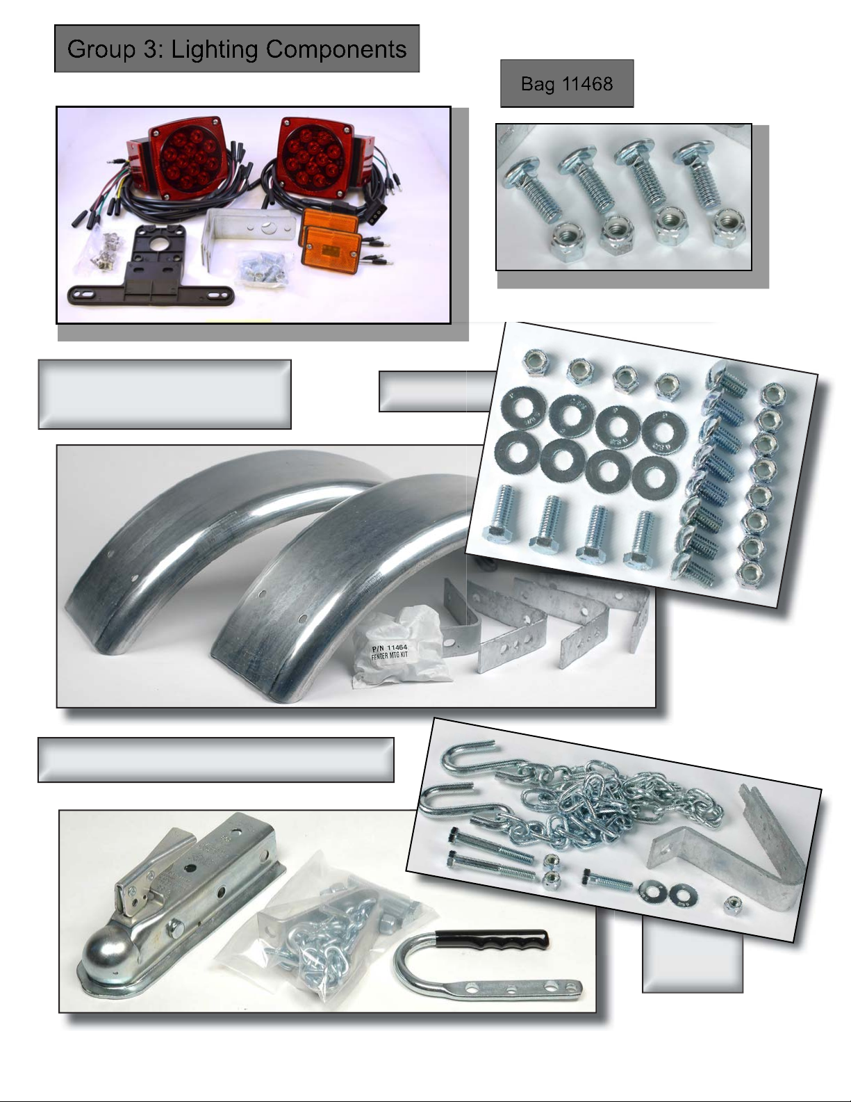
Bag 11462
Group 2:
Axle / Spring
Components Bag 11476
2 800-295-0042 ext. 215
Visit www.maloneautoracks.com/Replacement-Parts
for all of your spare part needs
Group 4:
Fender Components Bag 11464
Group 3: Lighting Components Bag 11468
Group 5: Coupler Components
Bag 11494
800-295-0042 ext. 215 3
Visit www.maloneautoracks.com/Replacement-Parts
for all of your spare part needs

MPG460G
Group 6:
Load Bar
Components
Bag 11489
X4
4 800-295-0042 ext. 215
Visit www.maloneautoracks.com/Replacement-Parts
for all of your spare part needs

800-295-0042 ext 206
MPG460G
FRAME ASSEMBLY (Group 1)
1. We assemble the frame on its back to make it easier to install the springs
and axle. Once the springs and axle assembly is installed we will flip the trailer
over to complete the assembly. So first, layout the frame components upside
down as shown. The spring bracket mounting holes should be facing up. All
the decals should be upside down.
2. Attach the spring
hanger brackets to the
frame. The U shaped
shackle bolt brackets
mount to the front and
the C shaped “slip-
per” brackets mount
to the rear as shown.
Use 3/8” x 1” bolts and
nuts. Assemble with
the nuts on the inside of the frame rails. Fully tighten all 8 bolts now.
3. Identify the hitch end of the tongue
by the 3 holes on the left side. Insert
the small wire protection grommet
into the lower hole where shown,
then push it all the way in till it snaps
in place.
3. Identify the hitch end of the tongue by the 3
holes on the left (drivers) side.
MALONE
R
800-295-0042 ext. 215 5

4. Pass the wiring harness (with a plug at each end), into the
open end of the tongue, leaving enough excess at the front to
reach the vehicle. NOTE: MAKE SURE YOUR PLUG
MATCHES THE VEHICLE CONNECTION. IF NOT REVERSE
YOUR WIRING HARNESS NOW.
800-295-0042 ext 206
MPG460G
7. Installing the rear tongue support
bracket. First we lay the tongue back in its
place making sure its upside down. Push
the large wire protection grommet into the
rear tongue support bracket hole, then
pass the wires through the grommet. In-
stall the 4-1/2” long x 1/2” bolt up from the
bottom through the tongue support and tongue. Be careful not to pinch the
wires. Add a washer and nut. Hand tighten only.
8. Bolt the tongue support to the frame
rails using 3/8” x 1” carriage head bolts.
Note the square heads go on the outside
with the square holes in the frame. As-
semble with washers and nuts on the
inside. Hand tighten only.
MPG460G
800-295-0042 ext 206
6
4. Pass the wiring harness into
the grommet and out the front
end of the tongue as shown.
Stretch out the white wire and
leave an equal length of the
green/brown/yellow wire outside
the grommet as shown. This
length of wires will be the con-
nector to your tow vehicle.
6. Now its time to pass the wire ends thru the tongue.
Make sure the wires are tangle free, then attach a
weight to the end of the wires. A large socket works
great as shown or you could tape a big bolt to the
wires. Tip the tongue up and let gravity work for you.
Feed the wire and let the weight slide through the
tongue pulling the wires with it.
5. Roll this wire so it
doesn’t get accidentally
pulled inside the tongue.
5. Installing the rear tongue support bracket. First we lay the
tongue back in its place making sure it’s upside down. Pass
the wiring through the support bracket hole.
6.Install the 4-1/2” long x 1/2” bolt up from the bottom through
the tongue support and tongue. Be careful not to pinch the
wires. Add washer and nut. Hand tighten only.
7. Bolt the tongue support to the frame rails
using 3/8” x 1” carriage head bolts. Note the
square heads go on the outside with the square
holes in the frame. Assemble with washers and
nuts on the inside.
8. Hand tighten only.
MALONE
R
6 800-295-0042 ext. 215

MPG460G
9. Clamp the frame rails around the
tongue as shown using two 1/2” x
3-1/4” bolts. Use a washer on both
sides. Hand tighten only.
10. Lay the two frame cross members
in between the frame rails. The two
holes in the middle should face DOWN
as shown. Bolt the frame rails to the
cross members using 3/8” x 1” carriage
bolts and nuts, (no washers). The square carriage heads go
to the outside with the square holes in the frame rails. Hand
tighten only.
10. Lay the two frame cross members
in between the frame rails. The large
Malone decal should be in the rear,
facing upside down. Bolt the frame rails
to the cross members using 3/8” x 1”
carriage bolts and nuts, (no washers).
The square heads go to the outside
with the square holes in the frame rails.
Hand tighten only
MALONE
R
800-295-0042 ext. 215 7

800-295-0042 ext 206
MPG460G
11. TIME TO TIGHTEN
FRAME BOLTS: Its important to
follow this tightening sequence in order
to insure the trailer will be straight after
everything is tight.
A) Tighten the 8 nuts holding the ends
of the two cross members.
C) Tighten the two tongue bolts
snug to the frame rails.
DON”T overtighten, you will just
crush the tongue.
B) Tighten the rear tongue support bracket. Check that
you installed washers under the 4 nuts as shown. Evenly
tighten the 4 nuts.
B) Tighten the rear tongue support
bracket. Check that you install
washers under the 4 nuts as
shown. Evenly tighten the 4 nuts.
MALONE
R
8 800-295-0042 ext. 215
MPG460G
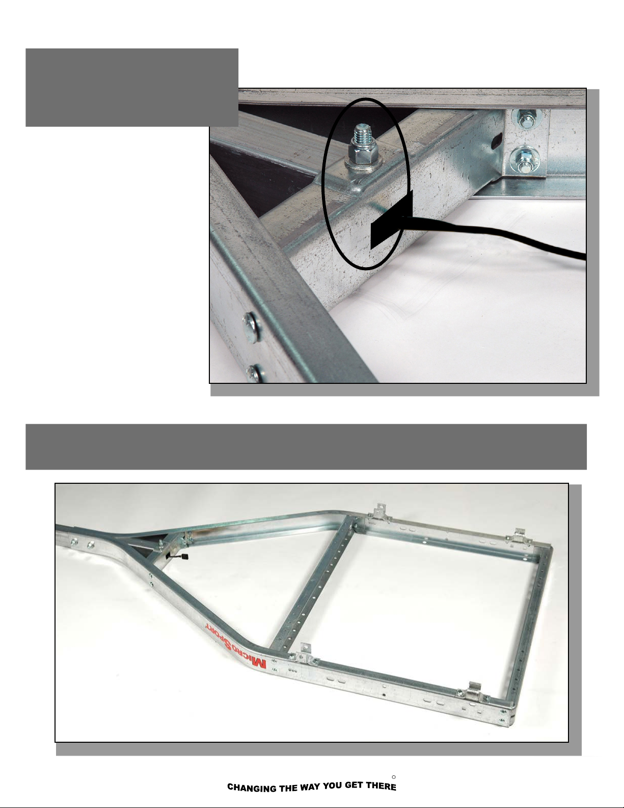
D) Tighten the big bolt thru the rear
of the tongue and tongue
support. Not too tight, don’t
crush the tongue or support.
Your frame assembly is now complete and should look like this.
D) Tighten the big bolt through
the rear of the tongue and tongue
support. Not too tight, don’t crush
the tongue or support.
Your frame assembly is now complete and should look like this.
MALONE
R
800-295-0042 ext. 215 9

800-295-0042 ext 206
MPG460G
SPRING AND AXLE ASSEMBLY
(Group 2)
2. Spin the axle to find the side with the spring
centering holes. These holes mate with the spring
center stud (shown to the left)
1. Set the envelope containing the manufac-
turer’s certificate of origin (MCO) and VIN labels
aside in a safe place.
MALONE
R
10 800-295-0042 ext. 215
*Set the large red envelope
(in the axle box) containing
important documents in a safe spot.

MPG460G
4. Run each nut down UNTIL IT
TOUCHES THE PLATE ONLY!
DON’T TIGHTEN !!
You will need to wiggle the
springs to fit them into the
spring brackets in the next step.
5. Lift the axle/spring assembly to the trailer frame and slide the slipper spring
ends into the slipper spring brackets as shown.
MALONE
R
800-295-0042 ext. 215 11

800-295-0042 ext 206
MPG460G
8. Wiggle the spring eyes into the front hanger brack-
ets and bolt using 1/2” x 3” bolts and self locking
nuts. Tighten the shackle bolts ONLY until they grip
the sides of the brackets. This is a hinge, the spring
needs to move freely.
10. Slip the hub caps thru the wheels
from the back then mount the wheels
onto the hubs and hand tighten the lug
nuts.
9. Now that the axle assembly is at-
tached to the frame, tighten the axle
plate U-bolts evenly until there is a
slight bend in the tie plates.
11. Stand behind the trailer, lift
the rear cross member at one
corner and flip the trailer over onto
the tires.
ALWAYS BEND FROM YOUR
KNEES WHEN LIFTING. IF THE
TRAILER IS TOO HEAVY FOR
YOU TO FLIP
SAFELY GET
SOME FRIENDS
TO ASSIST
YOU.
12. Tighten
the lug firmly
to 75 to 85 foot
pounds
of torque.
6.
8.
7.
9.
10.
MALONE
R
12 800-295-0042 ext. 215
MPG460G
800-295-0042 ext 206
14
REFERENCE:
Trailer Wiring Color Code
•Brown = running lights
•Yellow = left turn / left brake
•Green = right turn / right brake
•White = ground
2. Sandwich the license plate mounting
bracket between the left side lamp and the
left side tail lamp bracket. Attach the tail
light using the nuts provided with the lamp
kit. Then mount the right side lamp.
1. Attach the tail lamp brackets to
the frame as shown using 3/8” x 1”
carriage head bolts and nuts. No
washers are needed.
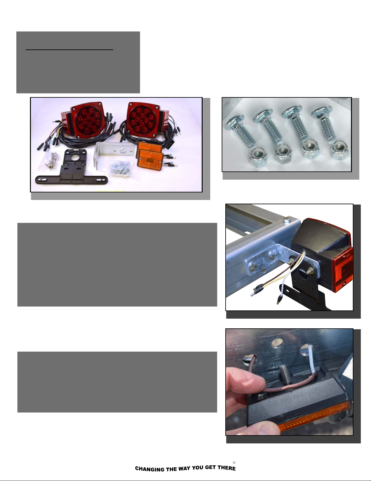
LIGHT ASSEMBLY (Group 3)
3. Use the holes just above the
spring bracket to mount the amber
side lamps. Put the stud through
the forward hole and the wire
through the rear hole. Tuck the wire
so the lamp sits flush on the frame.
L.E.D. REFERENCE:
Trailer Wiring Color Code
•Brown = running lights
•Yellow = left turn / left brake
•Green = right turn / right brake
•White = ground
1. First attach the tail lamp brackets to the frame as shown
using 3/8” x 1” carriage head bolts and nuts. No washers
are needed.
2. Mount the drivers side lamp to the lamp bracket. Attach/
secure the license plate holder to the backside of the lamp
bracket as shown. Secure tail light using the nuts provided
with the light kit. Then mount the passengers side tail light.
3. Use the holes just above the spring bracket to mount the
amber side lights. First, push the wire leads through the
outside holes and the lamp stud through the center hole.
MALONE
R
800-295-0042 ext. 215 13
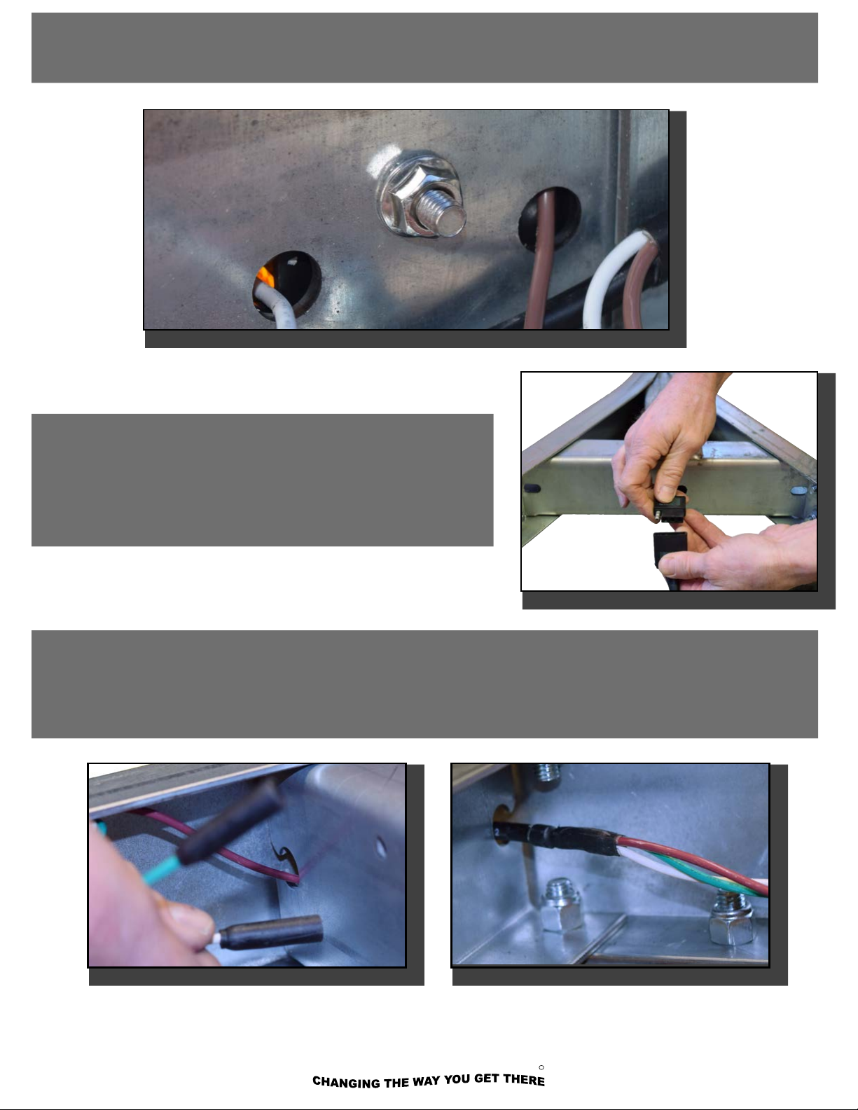
5. Plug in the remaining wiring harness into the connection
behind the tongue. Looking at the end connections, route
the GREEN/BROWN/WHITE wire along the passengers
side. Route the YELLOW/BROWN/WHITE along the
drivers side as shown.
6. Next, we’ll route the wires through the cross members, One lead at a time, all the way through the
trailer to the tail lights.
4. Secure with the lamp stud nut.
MALONE
R
14 800-295-0042 ext. 215

8. Use the clips provided to secure the wire to the inside of
the frame channel as shown.
NOTE: THESE UNUSED PLUGS ARE FOR AUXILIARY ACCESSORIES LIKE
THE MALONE MPG543 CHARGING UNIT AND/OR MPG539 FLOOD LIGHT
(NOT INCLUDED)
MPG539
MPG543
7. With the wires routed all the way to the tail lights, rmly
grasp the wiring connections and plug-in matching colored
leads/wires. Repeat with all remaining lights.
MALONE
R
800-295-0042 ext. 215 15

800-295-0042 ext 206
MPG460G
FENDER ASSEMBLY (Group 4)
1. Connect all 4 fender brackets to the fenders using 3/8” x 3/4” slot head
screws and nuts. Assemble with the nuts to the inside of the fenders as
shown. No washers here. Fully
tighten all 8 screws and nuts.
Note: fenders are
symmetrical and fit on
either side of the trailer.
MALONE
R
16 800-295-0042 ext. 215

MPG460G
5. Tighten bolts fully and repeat for other side.
Note that when bolting the mounting brackets to the frame you will install
a washer on both sides, under the head of
each bolt and under each nut.
4. Using 3/8” x 1” bolts, washers on both
sides, and nuts, attach the fender brackets
to the slotted holes in the frame as shown.
NOTE you will use the center hole in the
bracket and the outside two slotted holes in
the frame.
MALONE
R
800-295-0042 ext. 215 17
800-295-0042 ext 206
MPG460G
1. Installing the ground wire con-
nector. Strip 3/8” of insulation off the
white ground wire and crimp on the
ring connector as shown.
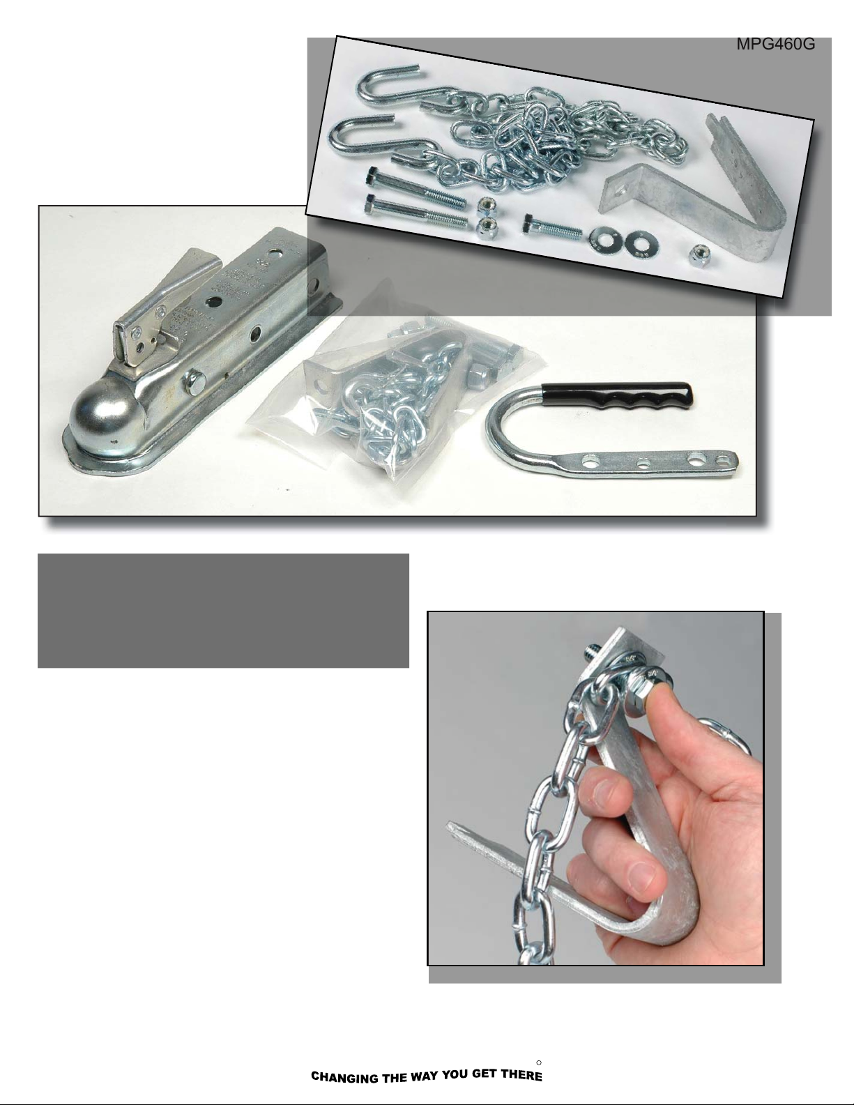
2. Assemble the tongue skid and safety chain assembly
with a 3/8” x 1-1/2” bolt as shown. Use washers above
and below the chain ends.
COUPLER ASSEMBLY
(Group 5)
1. Assemble the tongue skid and safety chain
assembly with a 3/8” x 1-1/2” bolt as shown.
Use washers above and below the chain ends.
800-295-0042 ext 206
MPG460G
1. Installing the ground wire con-
nector. Strip 3/8” of insulation off the
white ground wire and crimp on the
ring connector as shown.
2. Assemble the tongue skid and safety chain assembly
with a 3/8” x 1-1/2” bolt as shown. Use washers above
and below the chain ends.
COUPLER ASSEMBLY
(Group 5)
MALONE
R
18 800-295-0042 ext. 215
Other manuals for MPG460G
1
This manual suits for next models
6
Other Malone Boating Equipment manuals


