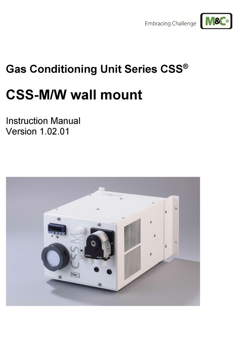
M&C PSS Series User manual

Gas Conditioning Unit Series PSS®
SS-M05 for Marine Application
Instruction Manual
Version 1.01.00

2 SS-M05_Marine | 1.01.00 www.mc-techgroup.com
Dear customer,
Thank you for buying our product. In this manual you will find all necessary information about this M&C
product. The information in the manual is fast and easy to find, so you can start using your M&C product
right after you have read the manual.
If you have any question regarding the product or the application, please don’t hesitate to contact M&C
or your M&C authorized distributor. You will find all the addresses in the appendix of this manual.
For additional information about our products and our company, please go to M&C’s website
www.mc-techgroup.com. There you will find the data sheets and manuals of our products in German
and English.
This Operating Manual does not claim completeness and may be subject
to technical modifications.
© 07/2019
M&C Techgroup
Germany GmbH. Reproduction of this
document or its content
is not allowed without permission from M&C.
PSS
®is a registered trade mark.
Version: 1.01.00

www.mc-techgroup.com SS-M05_Marine | 1.01.00 3
List of Contents
1General Information ..................................................................................................................5
2Declaration of Conformity ........................................................................................................5
3Safety Instructions....................................................................................................................6
3.1 Intended Use .......................................................................................................................6
3.2 Qualified Personnel..............................................................................................................6
3.3 Electrical Voltage .................................................................................................................7
4Warranty ....................................................................................................................................8
5Used Terms and Signal Indications.........................................................................................9
6Introduction.............................................................................................................................11
6.1 Serial Numbers ..................................................................................................................11
6.2 Power Supply.....................................................................................................................11
7Application ..............................................................................................................................12
8Technical Data.........................................................................................................................14
8.1 Dimensions ........................................................................................................................15
9Description ..............................................................................................................................16
10 Receipt of Goods and Storage ...........................................................................................17
11 Installation ...........................................................................................................................17
11.1 Connecting the Sample Gas Line.......................................................................................18
12 Connecting the Tubing........................................................................................................20
12.1 Media Connections ............................................................................................................20
12.2 Electrical Connections........................................................................................................22
12.3 Electrical Installation ..........................................................................................................23
13 Starting.................................................................................................................................24
13.1 Function Sequence and LED Function Display ..................................................................25
14 Closing Down ......................................................................................................................26
15 Maintenance.........................................................................................................................27
15.1 Maintenance Cooler...........................................................................................................28
15.1.1 Replacing the Heat Exchangers..................................................................................28
15.2 Maintenance Peristaltic Pump............................................................................................29
15.2.1 Changing the Pump Tubing ........................................................................................30
15.2.2 Changing Contact Pulleys and Springs .......................................................................31
15.2.3 Reassembly of the Driver............................................................................................32
15.2.4 Cleaning the Pump Head ............................................................................................33
15.2.5 Repair Information ......................................................................................................33
15.3 Maintenance Sample Gas Pump........................................................................................34
15.3.1 Replacing the Valve Plates .........................................................................................35
15.3.2 Replacing the Bellows.................................................................................................37
15.3.3 Cleaning Instructions ..................................................................................................38
16 Trouble Shooting.................................................................................................................39
17 Disposal ...............................................................................................................................40
18 Spare Parts List ...................................................................................................................41
19 Appendix ..............................................................................................................................43

4 SS-M05_Marine | 1.01.00 www.mc-techgroup.com
List of Figures
Figure 1 Gas flow diagram............................................................................................................12
Figure 2 Dimensions and design SS-M05.....................................................................................15
Figure 3 Sample gas line connection............................................................................................18
Figure 4 Media connections 2 to 5................................................................................................20
Figure 5 Media connection for downstream analyzer....................................................................21
Figure 6 Cable glands ..................................................................................................................23
Figure 7 Terminals X1, X2, X3......................................................................................................24
Figure 8 Changing the pump tubing..............................................................................................30
Figure 9 Different pump tube sizes ...............................................................................................31
Figure 10 Disassembly of pump head and driver ........................................................................31
Figure 11 Check of axes and rolls...............................................................................................32
Figure 12 Sectional drawing MP-F.. ............................................................................................36
Figure 13 Wiring diagram part 1..................................................................................................44
Figure 14 Wiring diagram part 2..................................................................................................45

www.mc-techgroup.com SS-M05_Marine | 1.01.00 5
HEAD OFFICE
M&C TechGroup Germany GmbH Rehhecke 79 40885 Ratingen Germany
Telephone: 02102 / 935 – 0
Fax: 02102 / 935 – 111
E - mail: info@mc-techgroup.com
www.mc-techgroup.com
1 GENERAL INFORMATION
The product described in this instruction manual has been built and tested in our production facility.
All M&C products are packed to be shipped safely. To ensure the safe operation and to maintain the
safe condition, all instructions and regulations stated in this instruction manual need to be followed.
This instruction manual includes all information regarding proper transportation, storage, installation,
operation and maintenance of this product by qualified personnel.
Follow all instructions and warnings closely.
Read this manual carefully before commissioning and operating the device. If you have any questions
regarding the product or the application, please don’t hesitate to contact M&C or your M&C authorized
distributor.
2 DECLARATION OF CONFORMITY
CE - Certification
The product described in this operating manual complies with the following EU directives:
RoHS Directive
The requirements of the RoHS2 (‘Restriction of Hazardous Substances 2’) directive 2011/65/EU and its
annexes are met.
EMC-Instruction
The requirements of the EU directive 2014/30/EU “Electromagnetic compatibility“ are met.
Low Voltage Directive
The requirement of the EU directive 2014/35/EU “Low Voltage Directive“ are met.
The compliance with this EU directive has been examined according to DIN EN 61010.
Declaration of conformity
The EU Declaration of conformity can be downloaded from the M&C homepage or directly requested
from M&C.

6 SS-M05_Marine | 1.01.00 www.mc-techgroup.com
3 SAFETY INSTRUCTIONS
Follow these safety directions and instructions regarding installation, commissioning and
operation of the equipment:
Read this manual before commissioning and operating the product. Make sure to follow all safety
instructions.
Installation and commissioning of electrical devices must be carried out only by qualified skilled
personnel in compliance with the current regulations.
The installation and commissioning of the device must conform to the requirements of VDE 0100
‘Regulations on the Installation of Power Circuits with Nominal Voltages below 1000V’ and must be in
compliance with all relevant regulations and standards.
When connecting the device, make sure that the mains voltage is correct as specified on the nameplate.
Protection against damages caused by high voltages:
Disconnect the power supply before opening the device for access. Make sure that all extern power
supplies are disconnected.
Operate the device only in the permitted temperature and pressure ranges. The location class according
to DNV-GL can be found in the technical data of this instruction manual.
Check that the location is weather-protected. It should not be subject to direct rain or liquids.
This device is NOT certified to be installed or operate in explosive hazardous areas.
Installation, maintenance, inspections and any repairs of the devices must be carried out only by
qualified skilled personnel in compliance with the current regulations.
3.1 INTENDED USE
This product is intended for use as a gas conditioning device for gas treatment on ships. The location
class according to DNV-GL can be found in the technical data of this instruction manual.
Do not use the unit for any other purpose than for this purpose.
Improper use can lead to serious injuries, see the safety instructions at the appropriate place in this
manual.
3.2 QUALIFIED PERSONNEL
The gas treatment device must be operated only by qualified personnel.
Use of the system by unqualified persons or failure to observe the warning instructions in this instruction
manual or on the device/cabinet itself may result in serious physical injuries and/or material damage.
The instruction manuals for the individual components must also be observed. Only qualified personnel
are allowed to use and maintain this device.

www.mc-techgroup.com SS-M05_Marine | 1.01.00 7
Qualified personnel in the sense of the safety instructions in this instruction manual or on the product
itself are persons who
•as project personnel are familiar with the safety concepts of the gas treatment device, or
•as operating personnel are trained in the use of gas treatment devices and are familiar with the
contents of this manual relating to its operation, or
•as maintenance and/or service personnel have been trained in the repair of such devices of
automation technology and who are authorised to operate, to earth and to designate circuits and
devices/systems in accordance with the standards of safety technology.
3.3 ELECTRICAL VOLTAGE
All work, including in particular work on live components, must be carried out in accordance with current
applicable safety guidelines. The gas treatment device must in this case be switched off externally!
Danger of electric shock! Disconnect the device from the mains power supply before starting work.
Secure the system against being switched on again unintentionally.
This also applies to all devices and equipment connected to this device.

8 SS-M05_Marine | 1.01.00 www.mc-techgroup.com
4 WARRANTY
In case of a device failure, please contact immediately M&C or your M&C authorized distributor.
We have a warranty period of 12 months from the delivery date. The warranty covers only
appropriately used products and does not cover the consumable parts. Please find the complete
warranty conditions in our terms and conditions.
The warranty includes a free-of-charge repair in our production facility or the free replacement of the
device. If you return a device to M&C, please be sure that it is properly packaged and shipped with
protective packaging. The repaired or replaced device will be shipped free of delivery charges to the
point of use.

www.mc-techgroup.com SS-M05_Marine | 1.01.00 9
5 USED TERMS AND SIGNAL INDICATIONS
Danger
The ‘Danger’ warning sign indicates that death, serious injury and/or
significant material
damage will be the consequence, if the
appropriate precautions should not be taken.
Warning
The ‘Warning’ warning sign indicates that death, serious injury or
damage to property may occur if the relevant precautionary
measures are not observed.
Caution
The ’Caution’ warning sign indicates that slight personal injury can
occur if the appropriate safety precautions are not observed.
Caution
’Caution‘ indicates that damage to property can occur if the
appropriate safety precautions are not observed.
Attention
‘Attention’ indicates that an unintended result or situation can occur
if the corresponding information is not taken into account.
Note
‘Note’ indicates important information relating to the product or
highlights parts of the documentation for special attention.
Qualified personnel
‘Qualified personnel’ are experts who are familiar with the
installation, mounting, commissioning and operation of these types
of products.
High voltages!
Protect yourself and others against damages which might be caused
by high voltages.
Toxic!
Acute toxicity (oral, dermal, inhalation)!
Toxic when in contact with
skin, swollowed or inhaled.
Corrosive!
These substances destroy living tissue and equipment upon contact.
Do not breathe vapors; avoid contact with skin and eyes.
Container under pressure! Do not open the container!
Check pressure before opening the container and adjust to
atmospheric pressure.

10 SS-M05_Marine | 1.01.00 www.mc-techgroup.com
Wear safety glasses!
Protect your eyes while working with chemicals or sharpe objects.
Wear safety glasses to avoid getting something in your eyes.
Wear protective clothes!
Working with chemicals, sharpe objects or extremly high
temperatures requires wearing protective clothes.

www.mc-techgroup.com SS-M05_Marine | 1.01.00 11
6 INTRODUCTION
The gas treatment device is used for gas preparation of continuous measurement of emissions in
Marine applications. The system consists of a stainless steel housing which accommodates the main
components such as cooler, peristaltic pump, bellow valve pump, flowmeter with sensor and
components for auto calibration of the analyzer.
6.1 SERIAL NUMBERS
The serial number plate is located on the right side of the stainless steel housing.
Note
Please refer to this serial number if
you have any questions about
the device or if you need to order spare parts or consumables.
6.2 POWER SUPPLY
The valid supply voltage connections can be found on the type plate.

12 SS-M05_Marine | 1.01.00 www.mc-techgroup.com
7 APPLICATION
The gas conditioning device is ideally suited for both intermittent and continuous operation.
The components of the system SS-M05 are intended for "standard use." We also provide a wide
range of additional equipment and other components if special measurements are required.
Figure 1 Gas flow diagram
The sample gas is fed to the gas treatment device via a heated sample gas probe –E2 (supplied by
customer, SP180-H/MA) to the input of the gas cooler –E1. The gas treatment device supplies the
current for the self-regulating heated sample gas line between the sample gas probe and the cooler -E1.
The bellow valve pump –M1 has a needle valve to adjust the flow through the cooler –E1. The sample
gas enters the gas conditioning device through the cooler. The bellow pump -M1 pumps the gas through
the solenoid valve –Y1, the filter -FI1 and the flowmeter -FM1.
The 3/2 way solenoid valve –Y1 is used for the auto calibration function of the analyzer. The solenoid
valve –Y1 is controlled by the analyzer. To auto calibrate the analyzer air is fed through the filter -FI2.
The bellows pump -M1 pumps the sample gas further through filter –FI1 including condensate detection
B1 and flowmeter -FM1 including flow detection B2, to the output “A2” of the gas treatment device.
At the output A2 output an unheated Teflon® tube can be connected to the analyzer.
The flow detection B2 triggers an alarm contact, if the gas flow is too low.
The condensate forming in the gas cooler is transported to the condensate outlet by the peristaltic pump
–M2.

www.mc-techgroup.com SS-M05_Marine | 1.01.00 13
In case of liquid alarm at B1, pump -M1 is automatically switched off to protect the downstream analyzer.
The error messages can be routed to the signalling terminal block.
Note
Detailed technical information on the built-in analysis device, as the
sample gas cooler, the pumps etc. can be found in the attached
operating instructions.
The technical documentation supplied and the instructions
contained must be observed at all times.

14 SS-M05_Marine | 1.01.00 www.mc-techgroup.com
8 TECHNICAL DATA
Gas Conditioning Type
SS-M05 Marine
Part-No
03G6000
Classification
GL (Germanischer LLoyd ) DNVGL-CG-0339
Standortklassen
Temperature A
Moisture B
Vibration A
EMC A
Housing B
Sample outlet dew point
Range of adjustment: +2 to +15 °C [35.6 to 59 °F], factory
setting: +5 °C [41 °F]
Sample outlet dew point stability
At const. conditions: < ±0.1 °C [±0.18 °F]
Sample inlet temperature
Max. 70 °C [158 °F], saturated**
Sample inlet water vapor saturation
Max. +70°C** [158 °F**]
Gas flow rate/heat exchanger
Max. 100 l/h**
Number of heat exchangers
1
Heat exchanger material
SS 316Ti
Ambient temperature
+5° to +50 °C** [41 to 122 °F]
Storage temperature
-25 to +65 °C [-13 to 149 °F]
Pressure
Max. 1 bar above atmospheric pressure
Total cooling power
at 25 °C [77 °F]
ambient temperature
Max. 80 kJ/h
Sample gas connection inlet
Ø 6 mm* tube
Sample gas connection outlet
tubing connection DN 4/6
Condensate connection
tubing connection DN 4/6
Condensate removal
Peristaltic pump SR25.2W
Sample gas pump
MP-F05
Ready for operation
Approx. 10 min.
Power consumption
250 VA (up to max. 1600 VA with heated sample gas line)
Mains power supply
230 V ±10 % 50 or 115 V ±10 % 60 Hz
Electrical connection
Terminals: 2.5 mm2, cable glands 2 x M20
Status alarm: gas flow rate
1 change-over contact
Switching power: status alarm
250 V, 2 A, 500 VA, 50 W
Case protection
IP54, EN 60529
Electrical equipment standard
EN 61010
Housing color
RAL 9005, stainless steel RAL 9005/RAL 9003
Installation type
Wall mount
Over all dimension (W x H x D)
600 x 780 x 600 mm [≈ 23.6” x 30.7” x 23.6”] with opened door
Weight
≈30.0 kg [≈66.1 lbs]
* Standard
** Maximum values in technical data must be rated in consideration of total cooling capacity at 25 °C
[77 °F] ambient temperature and an outlet dew point of 5 °C [41 °F].

www.mc-techgroup.com SS-M05_Marine | 1.01.00 15
8.1 DIMENSIONS
Dimensions in mm
Gas cooler
Solenoid valve for test gas feeding
Sample gas pump MP-F 05 with needle valve
Filter FP-2T-D Filter porosity 2 μm with integrated liquid alarm sensor LA
Flow meter FM40 with flow monitoring FA-20mo
Peristaltic pump SR25 for continuous automatic condensate drainage
Figure 2 Dimensions and design SS-M05

16 SS-M05_Marine | 1.01.00 www.mc-techgroup.com
9 DESCRIPTION
All components of the gas conditioning system are either housed in a compact stainless
steel housing or attached to it.
The sample gas line is connected directly to the heat exchanger inlet of the sample gas cooler. The
sample gas cooler cools the sample gas down to 5 °C [41 °F]. The heat exchanger is placed inside a
heat-insulated cooling block. An electronically controlled (analog technology) Peltier element cools
the cooling block to a constant temperature of +5 °C [41 °F]. A PT100 sensor is used to measure the
temperature. The thermal energy generated by the cooling system is dissipated via a fan-cooled
heat sink.
The cooler is equipped with a temperature alarm contact that switches off the sample gas pump in
case of a temperature deviation of ±3 °C [±5.4 °F] from the factory set point (+5 °C [41 °F]).
The peristaltic pump removes the accumulated condensate.
Downstream the cooler, there is a micro-filter with a 2 μm filter element and integrated liquid alarm
sensor LA. In case of leaking, the liquid alarm sensor switches off the sample gas pump
automatically.
A PTFE bellows pump is attached to the outside of the housing. This pump draws the sample gas
from the sampling point via the sample probe SP180H/MA (sold separately) through the heated
sample gas line (optional) into the cooler and further through the micro-filter. In the outlet of the
sample gas pump a flow meter FM40 with flow monitor FA-20mo is integrated. The flow rate monitor
FA-20mo signals the failure of the sample gas flow.
The now filtered and dried sample gas is passed on to the analyzer.
To calibrate the system, there is a switchover for test gas feeding through a solenoid valve. The
switchover is implemented in the gas treatment device.

www.mc-techgroup.com SS-M05_Marine | 1.01.00 17
10 RECEIPT OF GOODS AND STORAGE
Warning
Heavy device!
Risk of injury when handling heavy equipment.
Do not lift, move or carry the device without help. A second person is
required to lift, move or carry the device.
The gas conditioning device SS-M05 is a completely pre-installed unit.
•Please remove the gas conditioning device carefully from the packaging. Check the scope of the
delivery specified on the delivery note. Please make sure that you have received all items stated
on the delivery note.
•Please check the unit for any transport damages after receipt and report any complaints to the
transport company immediately.
Note
The SS-M05 Marine system must be stored in a weather protected
frost free area.
11 INSTALLATION
Warning
Heavy device!
Risk of injury when handling heavy equipment.
Do not lift, move or carry the device without help. A second person is
required to lift, move or carry the device.
Before installation and commissioning of the gas conditioning device, the operating instructions of the
components used must be read and followed.
Note
The fan must have a minimum distance of 200 mm to adjacent devices or
boundaries.
•Install the gas conditioning device with a minimum distance of 200 mm between the fan and
adjacent equipment or boundaries.
•- The gas conditioning device is intended for wall mounting
Note
The equipment is to be used in a vertical position only. The perfect
functioning of the separation and drainage procedures will only be
guaranteed if the equipment is used in a vertical position.
Installation according to location classes, see chapter "8 Technical
data".
For outdoor installation, adequate protection against direct sunlight
and moisture must be provided. In winter, the installation site must be
frost-free; observe the degree of protection of the gas conditioning
device.

18 SS-M05_Marine | 1.01.00 www.mc-techgroup.com
Do not use the gas conditioning device at temperatures other than
those specified. This avoids false alarms and ensures the operational
safety of the gas conditioning system and the additionally connected
analyzer.
Downstream analysers and the unheated Teflon tubing must always
be operated at temperatures well above the specified gas output dew
point of +5 °C.
Unheated gas sample lines must be
installed with a slope down to the
cooler. Condensate pre-separation is then not necessary.
11.1 CONNECTING THE SAMPLE GAS LINE
Note
Do not mix up connections. The upper heat exchanger connection is the
inlet, the side heat exchanger connection is the outlet and the lower heat
exchanger connection is the condensate outlet.
The sample gas line is connected to the inlet of the external heat exchanger. The heated part of the
sample gas line should end approx. 30 cm in front of the heat exchanger.
The electrical connection of the sample gas line is made via the cable gland K1 at the upper left corner
of the SS-M05 system cabinet. The outlet of the heat exchanger must be connected to media
connection 1.
Cable gland K1 Media connection 1 Heat exchanger inlet (A1) and outlet
Figure 3 Sample gas line connection

www.mc-techgroup.com SS-M05_Marine | 1.01.00 19
Connect the heated sample gas line as follows:
1. Connect heated sample line –E2 to the inlet of the heat exchanger “A1”. At least 60 mm unheated
tube should be at the end of the heated line.
2. Check tightness!
3. Connect sample gas outlet.

20 SS-M05_Marine | 1.01.00 www.mc-techgroup.com
12 CONNECTING THE TUBING
Note
Do not confuse tubing connections; connections are marked
accordingly.
After connecting all tubing, check for leaks.
12.1 MEDIA CONNECTIONS
The condensate outlet of the heat exchanger is connected to the media connection 2.
Media connection 3 is the condensate outlet of the peristaltic pump. The media connection 3 must be
lead to a condensate collecting container supplied by the customer.
Bulkhead fittings 4 and 5 are connected to the inlet and outlet of the pump.
Media connection 2
Media connection 3
/Bulkhead fittings connected to the pump in-, outlet
Figure 4 Media connections 2 to 5
The output of the SS-M05 is connected to the downstream analyzer: Media connection 6.
Other manuals for PSS Series
5
This manual suits for next models
2
Table of contents
Other M&C Air Conditioner manuals
Popular Air Conditioner manuals by other brands

Fuji Electric
Fuji Electric RD-60FA Service manual

Frigidaire
Frigidaire FFMS121CQ10 installation manual

Hitachi
Hitachi YUTAKI Series instruction manual

Samsung
Samsung DC42GTVA Service manual

Frigidaire
Frigidaire FAA063P7A16 Use & care manual

Panasonic
Panasonic CS-KS18NB4UW & CZ-18BT1U + CU-KS18NKU manual