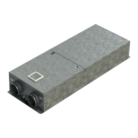
Mandik DM-S User manual


2
These technical specifications state a row of manufactured sizes and models of smoke dampers (further only dampers)
DM-S. It is valid for production, designing, ordering, delivery, assembly and operation.
1. Description.........................................................................................................................
3
2. Design................................................................................................................................
4
3. Dimensions, weights...........................................................................................................
4
4. Placement and Assembly....................................................................................................
6
5. Statement of installations....................................................................................................
7
6. Pressure loss and Noise data..............................................................................................
15
7. Electrical Components, Connection Diagrams....................................................................
16
8. Material............................................................................................................................. 17
9. Inspection, testing............................................................................................................. 17
10. Logistic terms....................................................................................................................
17
11. Assembly..........................................................................................................................
17
12. Entry into service and revisions.........................................................................................
18
13. Ordering key.....................................................................................................................
18

3
Smoke dampers are installed in duct served for smoke outlet. Damper closes the smoke duct.
Dampers are installed in the position "OPEN". Dampers blade automatically closes air duct using
an actuating mechanism back spring. The back spring of the actuating mechanism is started
when the thermoelectrical starting mechanism BAT is activated, when a reset button on BAT is
pushed or when a power supply of the actuating mechanism is stopped.
Working conditions
Right damper function is secured under the following conditions:
a) Maximum air circulation speed: 12 m/s
Maximum pressure difference: 1200 Pa
b) Dampers could be displaced into position “CLOSED” only in case that ventilator is
switched off. The goal is the securing of proper closing and safe function of Smoke
Damper in case of Fire.
c) The air circulation in the whole damper section must be secured as steady on whole
surface.
Damper characteristics
• Tested in accordance with EN 1366-2
• Classified acc. to EN 13501-3+A1 as E 30 ve, ho (i↔o) S or E 90 (ho i→o) or E 60 (ho i→o) S or
E 90 (ve i→o) S
• Fire resistance ES 30 (ES 60, E 90)
• ES Certificate of conformity No. 1391-CPR-2016/0083
• Declaration of Performance No. PM/DM-S/01/20/1
• Hygienic assessment of fire dampers - Report No. 1.6/pos/19/19b
Operation of the dampers does not depend on the direction of air circulation. The dampers can
be located in an arbitrary position.
Dampers are suitable for systems without abrasive, chemical and adhesive particles.
Dampers are designed for macroclimatic areas with mild climate according to EN 60 721-3-3.
Temperature in the place of installation is permitted to range from - 30°C to + 50°C.

4
DM-S is always equipped by actuating mechanism BFL (BFN, BF) 24-T (further only "actuating
mechanism"). After being connected to power supply AC/DC 24V, the actuating mechanism
displaces the damper blade into operation position "OPEN" and at the same time it pre-stretches
its back spring. When the actuating mechanism is under voltage, the damper blade is in the
position "OPEN" and the back spring is pre-stretched. Time needed for full opening of the flap
blade from the position "CLOSED" to the position "OPEN" is maximum 140s. If the actuating
power supply is cut off (due to loss of supply voltage, activation of thermoelectrical actuating
mechanism or pushing the reset button on the thermoelectrical starting mechanism BAT), the
back spring displaces the damper blade into the breakdown position "CLOSED". The time of
displacing the blade from the position "OPEN" to the position "CLOSED" takes maximum 16 s. In
case that the power supply is restored again (the blade can be in any position), the actuating
mechanism starts to re-displace the damper blade into the position "OPEN". A thermoelectrical
starting mechanism BAT, which contains two thermal fuses Tf1 and Tf2, is a part of the actuating
mechanism. These fuses are activated when temperature +72 °C has been exceeded (the fuse
Tf1 when the temperature around the damper and the fuses Tf2 when the temperature inside the
air-conditioning piping has been exceeded). After the thermal fuse Tf1 or Tf2 has been activated,
the power supply is permanently and irreversibly cut off and the actuating mechanism, by means
of the pre-stretched spring, displaces the damper blade into the breakdown position "CLOSED".
1 Damper body 3 Actuating mechanism
2 Damper blade 4 Inspection hole for camera
Dimensions

5
Weight and effective area
- - 2,6 0,0057 BFL
- - 2,8 0,0097 BFL
- - 2,9 0,0125 BFL
- - 3,2 0,0168 BFL
- - 3,3 0,0217 BFL
- - 3,5 0,0273 BFL
- 5 4,0 0,0440 BFL
28 38 4,6 0,0715 BFN
45,5 55,5 4,9 0,0886 BFN
48 58 5,0 0,0918 BFN
70 80 5,5 0,1176 BFN
120 130 6,6 0,1863 BFN
185 195 14,0 0,2138 BF
For round smoke damper the open damper blade overlaps the damper body from dimension
250 by the “c” or “a” and “c” values. These values are specified in the Tab. 3.2.1.
Value has to be respected when projecting related air-conditioning piping.

6
Damper assembly procedures must be done so as all load transfer from the fire separating
constructions to the damper body is absolutely excluded. Back-to-back air-conditioning piping
must be hung or supported so as all load transfer from the back-to-back piping to the damper is
absolutely excluded.
The distance between the smoke damper and the construction (wall, ceiling) must be min. 75mm.
In case that two or more dampers are supposed to be installed in one fire separating construction,
the distance between the adjacent dampers must be min. 200 mm according to EN 1366-2
paragraph 13.5.
The control mechanism has to be protected (covered) against damage and pollution during
installation process.
All smoke dampers have to be closed during installation process. The damper body should not
be deformed in the course of bricking in. Once the damper is built in, its blade should not grind
on the damper body during opening or closing.
Installation opening dimensions
Dampers are with rubber tightness and glued all the way around.

7
Statement of installations
Examples of smoke damper installing
The smoke damper can be installed into a solid wall construction made e.g. of normal
concrete/masonry, porous concrete with minimum thickness 100 mm or into solid ceiling
construction made e.g. of normal concrete/porous concrete with minimum thickness 150 mm.
Recommended installation openings are specified in Fig. 5.
The smoke damper can be installed into a gypsum wall construction with minimum thickness
100 mm
The smoke damper can also be installed outside of wall (ceiling) construction.
Damper installed in a solid wall construction. Space between damper and wall is filled
by mortar, gypsum or another approved fire sealing system for damper installation. ES 30 6
Damper installed in a solid wall construction. Space between damper and wall is
filled by mineral stone wool (min. density 140 kg/m³) or another approved fire
insulation system. Surface is covered by fire protection mastic (Promastop P,K) or
equal min. thickness 1 mm.
ES 30 7
Damper installed in a gypsum wall construction. Space between damper and wall is
filled by mortar, gypsum or another approved fire sealing system for damper
installation.
ES 30 8
Damper installed in a gypsum wall construction. Space between damper and wall is
filled by mineral stone wool (min. density 140 kg/m³) or another approved fire
insulation system. Surface is covered by fire protection mastic (Promastop P,K) or
equal min. thickness 1 mm.
ES 30 9
Damper installed in a solid ceiling construction. Space between damper and ceiling
is filled by mortar, gypsum or another approved fire sealing system for damper
installation.
ES 30 10
Damper installed in a solid ceiling construction. Space between damper and wall is
filled by mineral stone wool (min. density 140 kg/m³) or another approved fire
insulation system. Surface is covered by fire protection mastic (Promastop P,K) or
equal min. thickness 1 mm.
ES 30 11
Damper installed outside of a solid wall construction. Space between damper and
wall is filled by mortar, gypsum or another approved fire sealing system for damper
installation.
ES 30 12
Damper installed outside of a solid wall construction. Space between damper and
wall is filled by mineral stone wool (min. density 140 kg/m³) or another approved fire
insulation system. Surface is covered by fire protection mastic (Promastop P,K) or
equal min. thickness 1 mm.
ES 30 13
Damper installed outside of a gypsum wall construction. Space between damper and
wall is filled by mortar, gypsum or another approved fire sealing system for damper
installation.
ES 30 14
Damper installed outside of a gypsum wall construction. Space between damper and
wall is filled by mineral stone wool (min. density 140 kg/m³) or another approved fire
insulation system. Surface is covered by fire protection mastic (Promastop P,K) or
equal min. thickness 1 mm.
ES 30 15
Damper installed outside of a solid ceiling construction. Space between damper and
wall is filled by mortar, gypsum or another approved fire sealing system for damper
installation.
ES 30 16
Damper installed outside of a solid ceiling construction. Space between damper and
wall is filled by mortar, gypsum or another approved fire sealing system for damper
installation.
ES 30 17
Damper installed outside of a solid ceiling construction. Space between damper and
wall is filled by mortar, gypsum or another approved fire sealing system for damper
installation. BEWARE OF FIRE SIDE!
E 90, ES 60 18
Damper installed outside of a gypsum wall construction. Space between damper and
wall is filled by mortar and gypsum or another approved fire sealing system for
damper installation. BEWARE OF FIRE SIDE!
ES 90 19

8
1 Smoke damper DM-S
2 Mortar or gypsum
1 Smoke damper DM-S
3
Fire protection mastic Promastop P,K or equal min.
2Stuffing box (mineral stone wool min. density 140 kg/m³)
or another approved fire sealing system for damper
installation
thickness 1 mm

9
1 Smoke damper DM-S
2 Mortar or gypsum
1 Smoke damper DM-S
3
Fire protection mastic Promastop P,K or equal min.
2Stuffing box (mineral stone wool min. density 140 kg/m³)
or another approved fire sealing system for damper
installation
thickness 1 mm

10
1 Smoke damper DM-S
2 Mortar or gypsum
1 Smoke damper DM-S
3
Fire protection mastic Promastop P,K or equal min.
2Stuffing box (mineral stone wool min. density 140 kg/m³)
or another approved fire sealing system for damper
installation
thickness 1 mm

11
1 Smoke damper DM-S
2 Mortar or gypsum
1 Smoke damper DM-S
3
Fire protection mastic Promastop P,K or equal min.
2Stuffing box (mineral stone wool min. density 140 kg/m³)
or another approved fire sealing system for damper
installation
thickness 1 mm

12
1 Smoke damper DM-S
2 Mortar or gypsum
1 Smoke damper DM-S
3
Fire protection mastic Promastop P,K or equal min.
2Stuffing box (mineral stone wool min. density 140 kg/m³)
or another approved fire sealing system for damper
installation
thickness 1 mm

13
1 Smoke damper DM-S
2 Mortar or gypsum
1 Smoke damper DM-S
3
Fire protection mastic Promastop P,K or equal min.
2Stuffing box (mineral stone wool min. density 140 kg/m³)
or another approved fire sealing system for damper
installation
thickness 1 mm

14
1 Smoke damper DM-S
2 Mortar or gypsum
1 Smoke damper DM-S
3
Fire protection mastic Promastop P,K or equal min.
2Stuffing box (mineral stone wool min. density 140 kg/m³)
or another approved fire sealing system for damper
installation
thickness 1 mm
150

15
85 113 141 170 198 226 254 283 842
1122
1403
1683
1964
2244
2525
2806
4 6 7 8 10 11 12 14 3 4 5 7 8 9 10 11
19 26 32 37 41 45 48 50 6 13 19 24 28 31 34 37
12 21 33 47 64 84 106 131 1 1 2 3 4 5 6 8
133 177 221 265 309 353 398 442
1039
1385
1732
2078
2425
2771
3117
3464
4 5 6 8 9 10 11 13 3 4 5 7 8 9 10 11
20 27 33 38 42 45 48 51 7 14 20 25 29 32 35 38
9 16 25 36 49 65 82 101 1 1 2 2 3 4 5 7
166 222 277 333 388 443 499 554
1069
1425
1782
2138
2494
2851
3207
3563
4 5 6 7 9 10 11 12 3 4 5 6 8 9 10 11
20 27 33 38 42 45 48 51 6 13 19 24 28 32 35 37
8 14 21 31 42 55 69 86 1 1 1 2 3 4 5 6
217 290 362 434 507 579 651 724
1357
1810
2262
2714
3167
3619
4072
4524
4 5 6 7 8 10 11 12 3 4 5 6 7 9 10 11
18 25 31 36 40 43 46 49 6 14 20 24 28 32 35 38
5 10 15 22 30 39 49 61 0 1 1 1 2 3 3 4
275 366 458 550 641 733 824 916
2121
2827
3534
4241
4948
5655
6362
7069
4 5 6 7 8 9 11 12 3 4 5 6 7 8 9 11
17 24 30 35 39 42 46 48 4 12 18 22 26 30 33 36
4 7 11 16 22 29 36 45 0 0 1 1 1 1 2 2
339 452 565 679 792 905
1018
1131
3367
4489
5611
6733
7855
8978
10100
11222
3 5 6 7 8 9 10 12 4 6 7 9 10 12 13 15
16 23 29 34 38 41 44 47 4 12 18 22 26 30 33 36
3 5 8 11 15 20 25 31 0 0 0 1 1 1 2 2
530 707 884
1060
1237
1414
1590
1767
3 4 6 7 8 9 10 11
12 20 26 30 34 38 41 44
1 3 4 6 8 11 13 17

16
Actuating mechanism
Nominal voltage AC 24 V 50/60 Hz
DC 24 V
Power consumption - motoring
- holding
7 W
2 W
Dimensioning 10 VA (Imax 8,3 A @ 5 ms)
Protection Class III
Degree of protection IP 54
Running time - motor
- spring return
140 s
~ 16 s
Ambient Temperature - normal duty
- safety duty
- non-operating temperature
- 30 °C … + 50 °C
The safe position will be attained up to max. 75°C
- 40 °C … + 50 °C
Connecting - motor
- auxiliary switch
cable 1 m, 2 x 0,75 mm²
cable 1 m, 6 x 0,75 mm²
Thermal trips (Only for FDMA) Tf1: duct outside temperature 72°C
Tf2: duct inside temperature 72°C
12 S 3
S 1 S 2 S 5S 4 S 6
Connection via safety isolating transformer.
<5° <80°
BA T
T f T f LED
Parallel connection of other actuators possible. Observe the performance data.
Combination of power supply voltage and safety extra-low voltage not permitted
at the both auxiliary switches.
~
- +
Application examples for integration
into monitoring and control systems
or into bus networks can be found in
the documentation of the connected
communication and power supply unit.
1 = blue
2 = brown
S1 = violet
S2 = red
S3 = white
S4 = orange
S5 = pink
S6 = grey
Nominal voltage AC 24 V 50/60 Hz
DC 24 V
Power consumption - motoring
- holding
2,5/4 W
0,8/1,4 W
Dimensioning 4/6 VA (Imax 8,3 A @ 5 ms)
Protection class III
Degree of protection IP 54
Running time - motor
- spring return
<60 s
~ 20 s
Ambient temperature
- normal duty
- safety duty
- non-operating temperature
- 30 °C … 55 °C
The safe position will be attained up to max. 75°C
- 40 °C … 55 °C
Connecting - motor
- auxiliary switch
cable 1 m, 2 x 0,75 mm² (BFL/BFN 24-T-ST) with 3-pin plug-in connectors
cable 1 m, 6 x 0,75 mm² (BFL/BFN 24-T-ST) with 6-pin plug-in connectors
Thermal trips duct outside temperature 72 °C
duct inside temperature 72 °C

17
Damper bodies are supplied in the design made of galvanized plate without any other surface
finish.
Fasteners is galvanized.
The appliance is constructed and and preset by the manufacturer, its operation is dependent on
proper installation and adjustment.
Dampers are transported by box freight vehicles without direct weather impact, there must not
occur any sharp shocks and ambient temperature must not exceed + 40 °C. Dampers must be
protected against mechanic damages when transported and manipulated. During transportation,
the damper blade must be in the "CLOSED" position.
Dampers are stored indoor in environment without any aggressive vapours, gases or dust. Indoor
temperature must be in the range from -30 °C to +40 °C and maximum relative humidity 95 %
(avoid condensation on the damper body). Dampers must be protected against mechanic
damages when transported and manipulated.
All effective safety standards and directives must be observed during smoke damper assembly.
To ensure reliable smoke damper function it is necessary to avoid blocking the closing
mechanism and contact surfaces with collected dust, fibre and sticky materials and solvents.

18
Before entering the dampers into operation after their assembly and by sequential checks, the
following checks must be carried out.
Results of regular checks, imperfections found and all-important facts connected with the damper
function must be recorded in the "FIRE BOOK" and immediately reported to the operator.
Visual inspection of proper damper integration, inside damper area, damper blade, contact
surfaces and silicon sealing.
Before entering the dampers into operation after assembly and after sequential revisions, checks
and functionality tests of all designs including operation of the electrical components must be
done. After entering into operation, these revisions must be done according to requirement set
by national regulations.
In case that dampers are found unable to serve for their function for any cause, it must be clearly
marked. The operator is obliged to ensure so that the damper is put into condition in which it is
able to function and meanwhile he is obliged to provide the fire protection another appropriate
way.
Manual operation
Without power supply, the damper can be operated manually and fixed in any required
position. Release of the locking mechanism can be achieved manually or automatically
by applying the supply voltage.
technical specifications
size
type
Check of blade displacement into the breakdown position "CLOSED" can be done after cutting
off the actuating mechanism supply (e.g. by pressing the RESET button at the thermoelectrical
starting mechanism BAT or cutting off the supply from ELECTRICAL FIRE SIGNALISATION).
Check of blade displacement back into the "OPEN" position can be done after restoration of
power supply (e.g. By releasing the RESET button or restoration of supply from ELECTRICAL
FIRE SIGNALISATION).

The producer reserves the right for innovations of the product. For actual product information see
www.mandik.com
MANDÍK, a.s.
Dobříšská 550
26724 Hostomice
Czech Republic
Tel.: +420 311 706 706
E-Mail: [email protected]
www.mandik.com
Other Mandik Fan manuals