M&K Sound MPS2520P User manual

3
MPS2520P PROFESSIONAL MONITOR
OPERATION
MANUAL
MPS2520P
PROFESSIONAL MONITOR
Ver. 1.0 - MAY 2018
M&K Sound · Denmark· www.mksound.com

2 3
MPS2520P PROFESSIONAL MONITOR MPS2520P PROFESSIONAL MONITOR
Serial Number:
Date of Purchase:
Dealer Name:
Dealer Address:
City/State/Zip:
Country:
Invoice Number:
Table of contents
1. SAFETY INSTRUCTIONS ENGLISH & FRENCH ..................3-4
2. INTRODUCTION ..........................................5
3. VOLTAGE SELECTOR & POWER CORD ........................5
4. DESIGN FEATURES & SET UP GUIDANCE ...................... 5
5. INPUT & CONTROLS......................................6-8
6. OPERATION & BASS MANAGEMENT ........................8-9
7. ACCESSORY BRACKET & LINE DWG .........................10
8 TECHNICAL SPECIFICATIONS ............................... 11
Please record the following information for your records:
MPS2520P Manual Version 1 · May 2018
2
IN-WALL SUBWOOFER SYSTEM
1) Read these instructions.
2) Keep these instructions.
3) Heed all warnings.
4) Follow all instructions.
5) Do not use this apparatus near water.
6) Clean only with dry cloth.
7) Do not block any ventilation openings. Install in
accordance with the manufacturer’s instructions.
8) Do not install near any heat sources such as radia-
tors, heat registers, stoves, or other apparatus (includ-
ing amplifiers) that produce heat.
9) Do not defeat the safety purpose of the polarized
or grounding-type plug. A polarized plug has two
blade with one wider than the other. A grounding
type plug has two blades and a third grounding prong.
The wide blade or the third prong are provided for
your safety. If the provided plug does not fit into your
outlet, consult an electrician for replacement of the
obsolete outlet.
10) Protect the power cord from being walked on or
pinched particularly at plugs, convenience receptacles,
and the point where they exit from the apparatus.
11) Only use attachments/accessories specified by the
manufacturer.
12) Use only with the cart, stand, tripod,
bracket, or table specified by the manu-
facturer, or sold with the apparatus.
When a cart is used, use caution when
moving the cart/apparatus combination to
avoid injury from tip-over.
13) Unplug this apparatus during lightning storms or
when unused for long periods of time.
14) Refer all servicing to qualified service personnel.
Servicing is required when the apparatus has been
damaged in any way, such as power-supply cord or
plug is damaged, liquid has been spilled or objects
have fallen into the apparatus, the apparatus has been
exposed to rain or moisture, does not operate normal-
ly, or has been dropped.
15) The equipment shall be used at maximum 35-de-
gree C ambient temperature.
16) Do not open the equipment to reduce the risk of
electrical shock. For safety reasons it is only allow to
the opened by qualified service personnel.
17) WARNING: To reduce the risk of fire or electric
shock, do not expose this apparatus to rain or mois-
ture. And the apparatus shall not be exposed to
dripping or splashing and that no objects filled with
liquids, such as vases, shall be placed on the apparatus.
18) The MAINS plug is used as the disconnect device
and shall remain readily operable.
19) The product shall be used on open bench.
20) No naked flame sources, such as lighted candles,
should be placed on the apparatus.
21) The apparatus is suitable for use in tropical cli-
mates.
Important Safety Instructions
ATTENTION! RISQUE DE CHOC! ÉLECTRIQUE PAS OUVRIR!
Le symbole de l’éclair avec une flèche à son extrémité, dans un triangle
équilatéral, a pour but de vous avertir de la présence d’une « tension
électrique dangereuse » et non isolée à l’intérieur de l’enceinte de
l’appareil, qui peut être suffisamment puissante pour constituer un
risque d’électrocution pour les personnes.
Le point d’exclamation dans un triangle équilatéral vous avertit de
l’existence d’instructions importantes de fonctionnement et d’entretien
(intervention) dans la documentation accompagnant l’appareil.
ATTENTION! RISQUE DE CHOC! ÉLECTRIQUE PAS OUVRIR!
The lightning flash with arrowhead symbol, within an equilateral triangle,
is intended to alert the user to the presence of uninsulated dangerous
voltage within the product’s enclosure that may be of sufficient
magnitude to constitute a risk of electric shock to persons.
The exclamation point within an equilateral triangle is intended to
alert the user to the presence of important operating and maintenance
(servicing) instructions in the literature accompanying the appliance.

4 5
MPS2520P PROFESSIONAL MONITOR MPS2520P PROFESSIONAL MONITOR
3
IN-WALL SUBWOOFER SYSTEM
1) Lisez ces instructions.
2) Conservez ces instructions.
3) Observez tous les avertissements.
4) Suivez toutes les instructions.
5) N’utilisez pas cet appareil à proximité de l’eau.
6) Utilisez uniquement un chiffon sec pour le nettoy-
er.
7) Ne bloquez pas les ouvertures de ventilation.
Installez conformément aux instructions du fabricant.
8) Ne l’installez pas à proximité de sources de chaleur
telles que des radiateurs, des bouches de chaleur, des
poêles ou d’autres appareils (amplificateurs compris)
produisant de la chaleur.
9) Ne pas contourner le dispositif de sécurité de la
polarisation ou la prise de type mise à la terre . Une
fiche polarisée a deux lame avec une plus large que
l’autre . Une mise à la terre Type fiche comporte deux
lames et une troisième broche de mise à la terre . La
lame large ou la troisième broche sont fournies pour
votre sécurité, ta sécurité. Si la fiche fournie ne rentre
pas dans votre sortie, consultez un électricien pour le
remplacement de la prise obsolète.
10) Protégez le cordon d’alimentation, surtout au
niveau des fiches, des prises et des points où il sort
de l’appareil, pour éviter qu’on ne marche dessus ou
qu’on ne le pince.
11) Utilisez uniquement les accessoires spécifiés par le
fabricant.
12) Utilisez uniquement avec le chariot,
le socle, le trépied, la table ou le support
spécifié par le fabricant ou vendu avec
’appareil. En le fabricant ou vendu avec
l’appareil. Cas d’utilisation d’un chariot,faites attention
lorsque vous déplacez l’ensemble chariot / appareil de
ne pas le renverser.
13) Débranchez cet appareil lors d’orage avec foudre
ou lorsque vous ne l’utilisez pas pendant des périodes
prolongées.
14) Faites-le réparer et entretenir par un personnel de
service qualifié. Il est nécessaire de faire réparer l’appa-
reil lorsqu’il a subi des dommages quelconques du type
suivant : cordon ou fiche d’alimentation abîmé, liquide
renversé ou objets tombés dans l’appareil, exposition
de l’appareil à la pluie ou à l’humidité, mauvais fonc-
tionnement ou chute.
15) La température ambiante lors de l’utilisation ne
doit pas dépasser 35 degrés Celsius.
16) Afin de réduire les risques d’électrocution, n’ouvrez
pas l’équipement. Pour des raisons de sécurité, seul du
personnel d’entretien qualifié est autorisé à l’ouvrir.
17) ATTENTION: Pour réduire le risque d’incendie ou
d’électrocution, n’exposez pas cet appareil à la pluie
ou à l’humidité. De plus, l’appareil ne doit pas être ex-
posé au dégouttement ou aux éclaboussures et aucun
objet rempli de liquide, tel qu’un vase, ne doit être
posé sur l’appareil.
18) La fiche d’alimentation CA sert de principal disposi-
tif de déconnexion et doit toujours être capable de
fonctionner correctement.
19) Ce produit doit être utilisé sur une surface ouverte
20) Aucune source de flame nue, telle, que des bougies
allumées, ne doit être placé sur l’appareil.
21) L’appareil est adapté pour une utilisation dans les
climats tropicaux.
Consignes de sécurité importantes
ATTENTION! RISQUE DE CHOC! ÉLECTRIQUE PAS OUVRIR!
Le symbole de l’éclair avec une flèche à son extrémité, dans un triangle
équilatéral, a pour but de vous avertir de la présence d’une « tension
électrique dangereuse » et non isolée à l’intérieur de l’enceinte de
l’appareil, qui peut être suffisamment puissante pour constituer un
risque d’électrocution pour les personnes.
Le point d’exclamation dans un triangle équilatéral vous avertit de
l’existence d’instructions importantes de fonctionnement et d’entretien
(intervention) dans la documentation accompagnant l’appareil.
ATTENTION! RISQUE DE CHOC! ÉLECTRIQUE PAS OUVRIR!
The lightning flash with arrowhead symbol, within an equilateral triangle,
is intended to alert the user to the presence of uninsulated dangerous
voltage within the product’s enclosure that may be of sufficient
magnitude to constitute a risk of electric shock to persons.
The exclamation point within an equilateral triangle is intended to
alert the user to the presence of important operating and maintenance
(servicing) instructions in the literature accompanying the appliance.
2. INTRODUCTION
Congratulations and thank you for purchasing the MPS2520P This M&K Sound Professional powered
monitor is designed to provide many years of accurate and problem free operation.
We encourage you to read this owner’s manual, as there is a great deal of information provided here to
help you get the best possible performance from your new M&K Sound Professional monitor.
If you still have questions about your powered monitor after you have read this manual, please contact
your M&K Sound dealer or visit WWW.MKSOUND.COM
3. VOLTAGE SELECTOR & POWER CORD
Adjacent to the AC power cord receptacle on the back of the monitor you will find a voltage selector
switch pre-set at the factory for the proper local voltage.
The voltage input can be changed to the correct local voltage by sliding the selector to correct position.
Before changing voltage make sure the correct fuse value is present in the fuse holder.
For USA, Canada, Taiwan and Japan voltage 100/120 Volt, set voltage selector to 115Volt.
For Europe, the UK and Asia voltage 220/240 Volt, set voltage selector to 230Volt
Always check to make sure that your Monitor is set to your Country’s voltage.
If you have questions about this, contact your M&K Sound dealer.
DETACHABLE POWER CORD
Your new monitor is provided with a detachable power cord.
ALWAYS attach the cord to the monitor first, BEFORE plugging it into the AC wall socket.
4. DESIGN & SET UP GUIDANCE
M&K Sound design philosophy is that, accurate and lifelike sound and music reproduction takes place
when your ears, in effect, become the recording microphones. Our monitors are designed to allow you
to hear precisely what the microphones heard, placing you as close or as far away from the sound source
as the recording engineerplaced the microphones. To achieve this, your 2520P monitors are designed and
engineered to specifically produce a lively sound imaging in front of themselves.
The monitor design is featured with a true Bi-Amp design providing 200watt RMS amplifier power for the
midrange-woofers and 180watt RMS amplifier for the tweeter array, to ensure high sound quality and
a wide dynamic range. The 2520P offers extraordinary accuracy and flatness in both the frequency and
phase domains, that assures critical listeners of precision monitoring, for extended lengths of time with-
out any fatigue.
The 2520P are especially designed for high quality stereo and multi-channel mixing, in combination with
M&K Sound powered subwoofers and Bass management controller BMC-1.
Placing the 2520P for direct on-axis response in the listening position, provide the most accurate sound
image.Use the recessed LED light on front as the perfect “on-axis guide”, as when the LED light becomes
fully visible, the speaker is placed perfectly on axis for the listening position
Recommendable spacing between the speakers are app 2-3 meter (6.5-10 Feet) with a listening distance
of, 1,5-3 meter (5-10 Feet). In these ranges the speaker will perform with high precision and great imag-
ing.

6 7
MPS2520P PROFESSIONAL MONITOR MPS2520P PROFESSIONAL MONITOR
5. INPUT & CONTROLS
A Balanced XLR & 6,3 mm Jack input
B Balanced XLR & 6,3 mm Jack output (pass thru)
C Unbalanced input RCA
D Unbalanced output RCA (pass thru)
E Variable volume control
F Input sensitivity switch
G System and tweeter level trim
H Hihg pass filter selector
I Wide/narrow directivity selector
J Fuse holder
K Main Power switch
L Main Power socket
M Main Voltage selector
A
B
C
D
E
F
G
H
I
J
K
L
M
Balanced Input XLR / 6.3 mm Jack.
Balanced input for connection to professional mixing
equipment, soundcards & studio monitor controllers.
Balanced Pass Thru Output XLR / 6.3 mm Jack
Balanced pass Thru output connection for
linking up subwoofers or additional monitors
Unbalanced Input RCA.
Unbalanced input for connection to Hi-Fi preamps, TV set, or
general small portable sound devises.
Unbalanced Output RCA
Unbalanced Pass Thru output connection for linking up sub-
woofers or additional monitors
Input selection switch and variable gain control
7Switch position “REF” are calibrated for 90dB of acoustic output
at one meter with drive signal 200mV.
Use switch position REF when connecting 2520P to surround
receivers, 2 channel preamps or surround processors.
Use switch position “+4dBu” for connection to professional
mixing consoles or monitor controllers.
Switch position “Variable Gain” offers variable gain from -6dB to
+6dB relative to the reference position. Reference denotes the
position that should be used when operating this monitor with
+4dBu input signal. This control is only effective when the “Input
Gain Switch” is set to the position “Variable Gain”
System & Tweeter section trim
System and tweeter trim pots for “output level” calibration.
Using the trim pots will impact the factory preset frequency re-
sponse and output level and shall only be calibrated by qualified
engineers.
High Pass Filter selector
Select position “in” to activate the build in 80Hz high pass filter.
Activate the “high pass filter” when operating 2520P together
with subwoofers, and no separate bass management control are
in use.
Select position “out” to deactivate the “80Hz high pass filter”
when 2520P are used together with a separate bass manage-
ment control unit.
(See also page 9 for additional information)
A
B
C
D
E-F
G
H

8 9
MPS2520P PROFESSIONAL MONITOR MPS2520P PROFESSIONAL MONITOR
6. OPERATION & BASS MANAGEMENT
The 2520P monitor are specially designed to be used in combination with M&K Sound subwoofers, both in
setups with “external” bass management control units or without.
Using 2520P with the M&K Sound BMC-1 Bass management controller for 2 channel or multi-channel mix
setup, will provide the most correct set up conditions for 2520P and subwoofer(s). The M&K Sound BMC-1
Bass Management controller offers professional balanced connections for high pass and low pass filtering,
with individual channel level calibration for 2.1 or 5.1 setups for direct connection to 2520P monitors and
M&K Sound subwoofers.
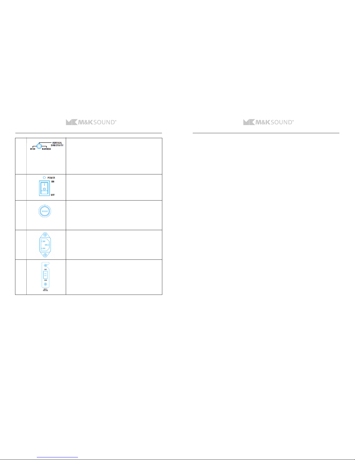
Wide / Narrow directivity selector
Select “Wide Mode” when 2520P are to be used as a
“free-standing” speakers in near to mid field positions.
Optional select “Narrow Mode” to activate vertical directivity
control for nearfield listening, if placing 2520P direct on mixing
consoles or close to reflecting surfaces.
Main Power on/off
Turns the system on/off.
Status LED are present on front and back of speaker.
Fuse holder
Fuse type T5AL 250Volt for 110 / 120 Volt
Fuse type T3.15AL 250 volt for 220 / 240 Volt
Caution! Always disconnect power cord before changing fuse,
Replace fuse only with same type.
Main Power socket
Use the included power chord for the main power connection.
Voltage selector 115 / 230 Volt.
Caution!
Always disconnect power cord and check the fuse has correct
value before changing the input voltage.
I
J
K
L
M
2520P High pass filter shall be set to position “OUT” when used together with M&K Sound Bass
management controller, and subwoofer crossover setting shall be “BY-PASSED” - as the Bass management
control unit will handle correct filtering for signals send to monitors and subwoofers.
When using the 2520P without a bass management control unit, the 2520P High pass filter shall be
activated to “IN” position” to cut of low frequency bass content from the monitors.
Connecting the M&K Sound subwoofers using the 2520P “Pass Thru” outputs create good “bass logic”
when either using 1 or 2 M&K Sound subwoofers, as M&K Sound subwoofers are featured with dedicated
input sockets for mono sub signals and Left and Right input signals.
In case of using 1 sub, the Left & Right main signal outputs from a mixer or monitor controller shall be
connected to the 2520P inputs for respective Left & Right speakers inputs, and by using the 2520P “Pass
Thru” output socket – the main signals will be carried on to the subwoofers and summed internally in the
subwoofer. The use of both Left & Right inputs on the subwoofer, will provide correct bass output by “one
subwoofer” in a given system setup.
In case of using two subs, the main Left & right signal outputs from a mixer or monitor controller will also
by using the “Pass Thru” connectors on the 2520P – route each main channel signal from source to each
subwoofer, which logically shall be connected to the subwoofers mono input socket.
In setups without a dedicated Bass Management controller, the subwoofers internal crossover filter
setting is the crucial feature to adjust for perfect match to the 2520P monitors. Typically, it will be
subwoofer crossover setting in the range between 100-120, Hz that will make good summation between a
pair of 2520P monitors and subwoofers.
When using 2520P together with other types of “studio monitor controllers” or HiFi preamps featured
with dedicated subwoofer output connections, then make sure to firmly check how these operates for sub
bass content.
Some units just have their left and right channels summed into a common “sub out” channel, while
the main channels at the same time provide full frequency bandwidth to their respective left and right
channel outputs.
In such setups the 2520P is recommended to operate with high pass filter activated (“IN” position) alike
setups without External Bass Management” - to make sure the Bass response of the 2520P will be
properly filtered.
If the studio monitor controller or HiFi preamp itself offers both high pass and low pass filtering, the
2520P shall be set to operate with High pass filter “out”, as then the monitor controller or HiFi preamp
will handle the crossover filtering between the subwoofer and 2520P monitor.
Using the 2520P with modern surround sound amplifiers or processors, the Bass management control will
be present by the surround sound “equipment”, and the 2520P shall also in such setups operate with High
pass filter in “OUT” position.
Modern surround amplifiers, processors and monitor controllers are according to their build in decoding
processors for various surround sound formats and crossover filter options, not always made with same
designs, and some products may offer more features than others.
Normally the basic options for proper Bass management control will be present in such dedicated
equipment, but always check the actual unit for their technical specifications, to make sure proper Bass
management control is possible to make, when using the 2520P monitor and M&K subwoofers in such
setups.

10 11
MPS2520P PROFESSIONAL MONITOR MPS2520P PROFESSIONAL MONITOR
7. ACCESSORY BRACKET & LINE DWG
For mounting MPS2520P on speaker stands, use the included L-bracket for adaption to either floor stands
or wall mount brackets. The Included L-bracket shall be attached to the speaker by using the included ¼
inch x 20 screws.
8. TECHNICAL SPECIFICATIONS
Amplifier power bass-midrange .......................................200watt RMS/400watt peak
Amplifier power high frequency.......................................180watt RMS/360watt peak
Bass-midrange ............................................................2 x 5.25” Glass fibre
High frequency drivers................................................. 3 x 1,1” soft fabric dome
Frequency response ...........................................80-12KHz +/-1dB / 12-20KHz +/-2dB
Total Harmonic distortion ..............0.002% into 4 ohms LF Channel / 0.03% into 4 ohms HF channel
Signal to noise ratio...................................................................100dB
AC power consumption ....................................Standby/Average/Max 17W, 45W, 360W
AC line voltage............................................115VAC/60Hz 5A - 230VAC/60Hz 3.15A
Input impedance unbalanced .........................................11Kohm / balanced 22Kohm
Input sensitivity unbalanced ............................ 100mV 90dB 1m / balanced 200mV 90dB 1m
Max output level ............................................................... 110dB/100Hz
Max input ...................................................................24dBu balanced
High pass filter .............................................................Fixed 80 Hz (24dB)
Vertical directivity control ..............................................Wide/Narrow – 50/30 Deg
Dimensions H X W X D......................................32.7 x 27 x 40.1 cm / 12.8 x 10.6 x 15.8”
Weight ....................................................................... 18 kg/39.6lbs
Finish...........................................................................Black Satin
Table of contents
Other M&K Sound Speakers System manuals