Manley Backbone User manual


CONTENTS
INTRODUCTION....................................................................................................................................3
MAINS CONNECTIONS........................................................................................................................4
THE FRONT PANEL...............................................................................................................................5
SIGNAL FLOW....................................................................................................................................6-9
Input Selection......................................................................................................................6
Input/Output Level Trims.....................................................................................................6
Inserts 1-3 (SUM-DIFFERENCE processing).....................................................................7
Inserts 4, 5 (SWAP).......................................................................................... ...................8
Inserts 6-8.............................................................................................................................8
Mix/Fade Knob....................................................................................................................8
Output Level Switches.........................................................................................................9
THE BACK PANEL.........................................................................................................................10, 11
THE GUTZ.............................................................................................................................................12
SOME THOUGHTS FROM OUR LAB...........................................................................................13-16
LABELING YOUR SWITCHES............................................................................................................16
TROUBLESHOOTING..........................................................................................................................17
PATCHABLE SENDS/RETURNS.........................................................................................................18
ELCO PINOUT.......................................................................................................................................19
DB-25 PINOUT.......................................................................................................................................20
Y-CABLE DIAGRAM............................................................................................................................21
BLOCK DIAGRAM...............................................................................................................................22
PARALLEL PROCESSING DIAGRAMS.............................................................................................23
DC-COUPLING I/O MODIFICATION.................................................................................................24
SPECIFICATIONS.................................................................................................................................25
TEMPLATE FOR STORING SETTINGS.............................................................................................26
rev 4.19.11 CD

INTRODUCTION
THANK YOU!…
…for purchasing the Manley Laboratories Mastering BACKBONE. This product is the culmination of
many custom Manley mastering consoles and mastering processors we have built over the years. When
we started building custom consoles in 1990 the only option for mastering houses was to commission
purpose-built systems from rare engineering shops like ours. We began to attract top mastering engi-
neers who would approached us and request audiophile grade consoles and dedicated mastering ver-
sions of our compressors and EQs. We were happy to listen and oblige - and frankly, somebody had to
support that neglected side of the business.
Overthenextdozenyears,masteringbusinessesourishedandbranched,andmanymoreaudio
companiesdevelopedproductsaimedspecicallyformastering.Infact,awholenewsub-category
of mastering grew out of this, most often called “project mastering”. We were getting deluged with
requestsforcustomprojectsatapointintimewhenitwasdifculttokeepupwithordersforstan-
dard products. We had to limit the number of custom projects we could accept, and even those were
beginning to take too long to build and test. Eventually we stopped accepting custom work altogether.
Meanwhile, several smaller companies were beginning to market non-custom off-the-shelf mastering
consoles (some remarkably similar to ones we had built).
However, even with several companies building reasonable mastering consoles, we were still get-
ting requests for something similar; not custom, but “Manley, like the famous guys use.” The Manley
BACKBONE is one part of our solution. In fact, it represents an evolution in performance from where
we left off in our custom designs.
The Manley BACKBONE is built with a unique electronic topology that maintains a fully balanced
signal path through 95% of the console. All other designs require the balanced signals to be converted
to unbalanced before sections that, for example, allow you to boost or cut level, then inversely need to
be converted back to balanced to feed the outside world. In other words, this new topology not only
does it in one stage rather than three or four stages, but also does it as cleanly and quietly as any single
stage could that we know of, including fully discrete approaches. This topology also provides better
commonmoderejectionandpowersupplynoiserejectionthanconventionalapproaches.Thisissigni-
cant especially in the “Sum-Difference” functions.
Each of the 10 gain blocks and all of the switches are on connectors, which means if the unit ever
requires service, repair can likely be done quickly without the need for a technician or soldering iron
– just a medium-small Philips screwdriver. No expense was spared in the quality of the parts, so one
should expect many years of continuous professional use.
Please note that this is not a “Monitor Control Box.” The Manley BACKBONE is simply a device
thatroutesvariousanalogprocessorswithmaximumdelityandallowsyoutomaintaintheshortest
possiblesignalpathswhileprovidingsomeexiblecentralcontrolfunctions.Thisunitisnotsupposed
to color your sound in the least (excepting the SUM-DIF feature, of course); it just exists to let you use
your favorite outboard gear in more creative ways.
3

MAINS CONNECTIONS
Your BACKBONE has been factory set to the correct mains voltage for your country. The voltage setting is
marked on the serial badge, located on the rear panel. Check that this complies with your local supply.
Exportunitsforcertainmarketshaveamouldedmainsplugttedtocomplywithlocalrequirements.Ifyourunit
doesnothaveaplugttedthecolouredwiresshouldbeconnectedtotheappropriateplugterminalsinaccordance
with the following code:
GREEN/YELLOW EARTH
BLUE NEUTRAL
BROWN LIVE
As the colours of the wires in the mains lead may not correspond with the coloured marking identifying the termi-
nals in your plug proceed as follows:
The wire which is coloured GREEN/YELLOW must be connected to the terminal in the plug which is
marked by the letter E or by the safety earth symbol or coloured GREEN or GREEN and YELLOW.
The wire which is coloured BLUE must be connected to the terminal in the plug which is marked by the letter
N or coloured BLACK.
The wire which is coloured BROWN must be connected to the terminal in the plug which is marked by the
letter L or coloured RED.
DO NOT CONNECT/SWITCH ON THE MAINS SUPPLY UNTIL ALL OTHER CONNECTIONS HAVE
BEEN MADE.
Note: This unit has been factory wired for your country. If you plan to take the unit to countries with a differ-
ent mains voltage you will need to send the BACKBONE to a qualied service technician or to the Manley Labs
Service Center for the correct transformer primaries wiring conversion. Alternatively, you may use outboard
AC voltage step-up or step-down transformers as appropriate.
TRANSFORMER WIRED IN PARALLEL for 100V and 120V operation. Uses a 1A SLO-BLO fuse.
TRANSFORMER WIRED IN SERIES for 220-240V operation. Uses a 0.5A SLO-BLO fuse.
***Fuses for ALL VOLTAGES are 5x20mm GDC packaged fuses.***
Waste Electrical and Electronic Equipment (WEEE)
Information for customers:
The European Parliament and the Council of the European Union have issued the Waste Electrical and Electronic Equipment Directive. The purpose of the Direc-
tive is the prevention of waste of electrical and electronic equipment, and to promote the reuse and recycling and other forms of recovery of such waste. As such
the Directive concerns producers, distributors and consumers.
The WEEE directive requires that both manufacturers and end-consumers dispose of electrical and electronic equipment and parts in an environmentally safe man-
ner, and that equipment and waste are reused or recovered for their materials or energy. Electrical and electronic equipment and parts must not be disposed of with
normal household wastage; all electrical and electronic equipment and parts must be collected and disposed of separately.
Products and equipment which must be collected for reuse, recycling and other forms of recovery are marked with the following pictogram:
Smallproductsmaynotalwaysbemarkedwiththispictograminwhichcasethisispresentintheinstructionsforuse,ontheguaranteecerticateandprintedon
the packaging.
When disposing of electrical and electronic equipment by use of the collection systems available in your country, you protect the environment, human health and
contribute to the prudent and rational use of natural resources. Collecting electrical and electronic equipment and waste prevents the potential contamination of
nature with the hazardous substances which may be present in electrical and electronic products and equipment.
Your MANLEY or LANGEVIN retailer will assist with and advise you of the correct way of disposal in your country.
4
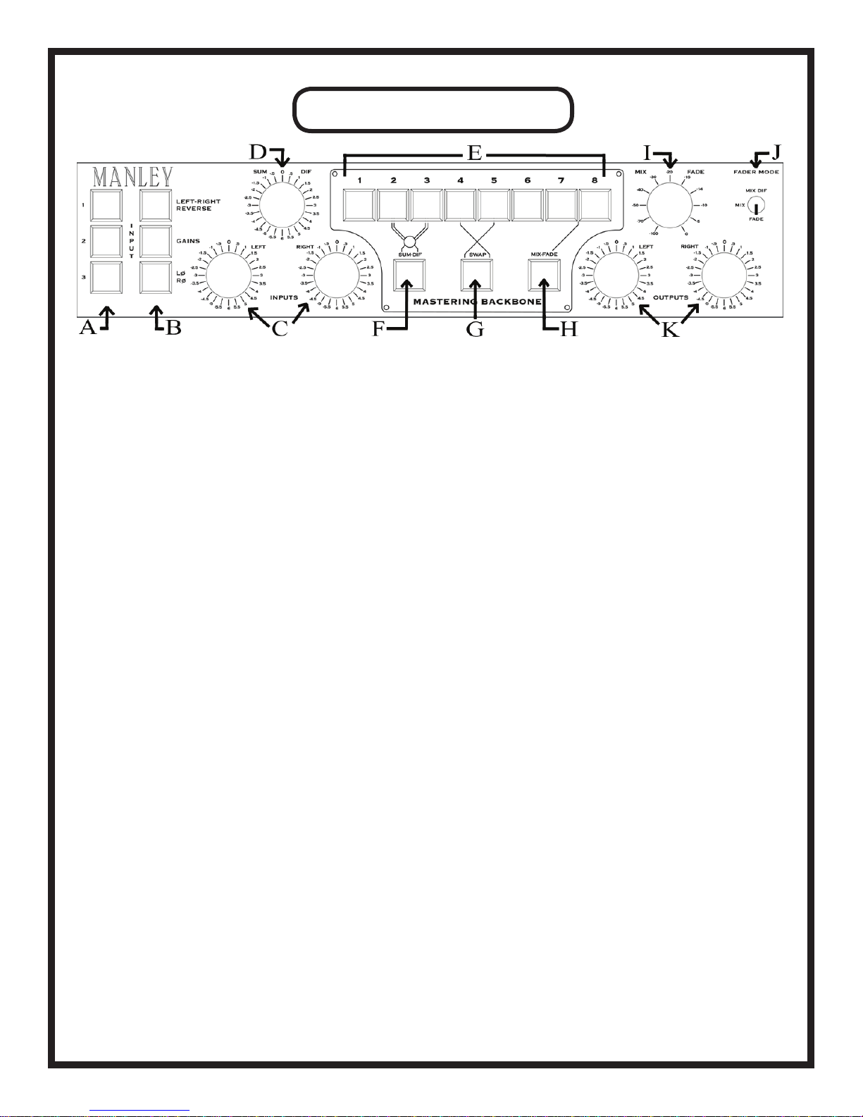
THE FRONT PANEL
A. INPUT 1, 2, 3: Choose which of the three inputs will drive the BACKBONE audio chain. Whichever
source is selcted here will also come out of the “SELECTED INPUT” XLRs on the back panel.
B. LEFT-RIGHT REVERSE: Allows you to swap left and right channels.
GAINS: When lit, engages all active electronics for the input and output gains.
LØ RØ (polarity reverse): Changes the absolute polarity of the signal on both channels. For more on
this, see page 6.
C. INPUTS: Input signal level for each channel can be selected on these 24-position, 1/2 dB stepped con-
trols. Range is from +6 to -5.5 dB.
D. SUM-DIF Rotary Switch: Alters the level of the DIFFERENCE signal sent to Inserts 2 and 3. Acti-
vated only when the SUM-DIF button (F in this diagram) is engaged. For more info, see pages 7 & 13.
E. Inserts 1-8: Push to activate the outboard processor that is patched into that insert point. See page 7-8
for details.
F. SUM-DIF: Press to engage SUM-DIF circuit for processing of Inserts 2 & 3.
G. SWAP: Swaps the order of Inserts 4 & 5 so that Insert 5 comes before Insert 4 when engaged (illumi-
nated). See pages 8 and 13 for info and suggestions.
H. MIX-FADE Button: Activates the MIX-FADE knob (Iin this diagram).
I. MIX-FADE Knob: Acts as a master fader or mixer, depending on the position of the FADER MODE
SWITCH (Jin this diagram). For a detailed explanation, see pages 8 and 15.
J. FADER MODE Switch: This is a 3-position switch (Iin this diagram) that determines the operating
mode of the MIX-FADE knob. The three modes are MIX DIF, MIX, and FADE. See pages 8 and 15
for more info.
K. OUTPUTS: Output signal level for each channel can be selected on these 24-position, ½ dB stepped
controls. Range is from +6 to -5.5 dB.
5

SIGNAL FLOW
INPUT SELECTION
Thesignal-owthroughtheBACKBONEissimpleenoughtodescribeandmostlyfollowsthefront
panel left-to-right layout. Three pairs of XLRs on the back panel are balanced line inputs associated
with the client’s sources. Typical sources might be a superb DAC (or two) or an analog tape machine.
Next come a pair of XLRs that are direct outputs of the chosen input. Typically these outputs would
feed a pair of monitor control box inputs and are used for comparing the raw tracks that were brought
inversustheprocessedsignal.Masteringengineersmayusethisasa“condencecheck”andasanim-
mediate way to show the client the “before and after pictures”. There are other outputs that can be used
tocheckthenaloutputafterprocessors,andforamid-pointintheprocessorchainifdesired.
The chosen input’s Left and Right channels can be swapped just for those occasional sessions when
either the mixing studio accidentally swapped cables or the mix seems to sound better in the opposite
perspective. Absolute polarity can also be reversed. This reverses the “phase” (polarity is the cor-
rect term) of both the left and right channels. Usually one wants the kick drum pushing the speaker
out rather than sucking the speaker inward. Most of the time, “Polarity Reverse” is a subtle effect and
with some mixes the effect is inaudible. Strangely, the effect is often most pronounced on reed instru-
ments and some types of vocal character. It is usually worth a quick check to verify which way seems
to sound best and/or seems to have the kick pushing the woofer outward. If in doubt, leave the absolute
polarity alone.
The Input Selection, Left-Right Reverse and Polarity Reverse are accomplished purely passively,
and are highly unlikely to damage the signals at all. This is achieved with simple sealed gold-contact
relay closures. In fact, the Left channel and Right channel signal paths are mainly kept on separate
circuit boards and/or widely separated physically to maintain maximum channel separation and low
cross-talk. Where a signal meets a connector, two gold contact pins and two wires are used for extreme
reliability. That feature is called “redundancy” so that if one expects one failure in one thousand with
only one connector, one might expect one failure in a million with doubled contacts (1,000 X 1,000).
INPUT LEVEL SWITCHES
Next up are the two INPUT LEVEL rotary switches that provide 24 precise ½ dB gain steps. The
rangeisfrom6dBofboostto-5.5dBofattenuation.Weselectultra-lowdistortionthinlm0.1%tol-
erance resistors and sealed gold contact Greyhill switches for near perfect tolerence and matching. As
described earlier, the gain stage is a fully balanced circuit followed by a pair of unity gain high current
buffers. “Nearly inaudible” is the goal here.
There is a GAINS switch that engages active electronics for both the INPUT LEVEL and OUTPUT
LEVELcontrolcircuits.Thisisonemoreformofcondencecheckthatallowsyoutocomparewhether
twosetsofgainstageshaveanyaudiblefootprint,whetherdetrimentalorbenecial.Italsoallowsone
to run the console in a 100% passive mode.
6

Generally the INPUT and OUTPUT LEVELS are meant to correct for any losses or unintentional
gains from the source machines or in any of the outboard processing gear. However, these controls
really open a lot of possibilities in terms of driving gear hotter or softer especially when one considers
combining that concept with setting up outboard gain settings away from a standard unity gain setting.
The issue here is “the sweet spot” or “gain staging” and the fortunate or unfortunate aspect of many de-
vices that just seem to sound best when driven a little harder or softer than the designer intended. One
can think of it a bit like a guitar amp with its input pot and master volume to get the right amount of
distortion at a comfortable stage volume. Or, one might be more familiar with analog mixing consoles
andlikenittondingthatmagiccombinationofindividualfaderlevelsandmix-busfaderlevel.
***In some cases, for “absolute purist fanatics”, even these buffers can be bypassed/removed
(by removing the chips and inserting small jumper wires between pins 3 and 8 on the dip socket)
for one less gain stage in the path – BUT in general they serve a number of benecial purposes
(including isolating the cable and destination electronics from the gain stage’s feedback loop)
whereas buffer-ectomy may have more of an imaginary benet . If you can’t hear any change of
quality bypassing ALL the electronics in the console (and so far that is the unanimous opinion),
then don’t even think of possible mods and variations (especially a mod that might be a detriment
in practice). Keep in mind, it also isn’t the kind of change that can be truly A-B compared…***
INSERTS 1-3…SUM-DIFFERENCE PROCESSING
OK, back to the idiosyncrasies of this Insert Box. Next in the signal path is INSERT #1. Pushing
the button marked INSERT 1 engages whatever box might be connected there. When the button is NOT
pushed and lit the main audio path is hard-wire bypassed, of course. However, a little isolation ampli-
erisengagedtofeedthatbox.Thisistopre-driveacompressorsothatitisalreadydoingappropriate
gain reduction at the moment that you do insert it. This prevents momentary level changes.
INSERT 2 and INSERT 3 are special. Below these button is another button labeled SUM-DIF
which engages a complete set of Sum / Difference encoders and decoders (or is it the other way
around?). Some people refer to this as M-S (or Mid-Side) but there are also those who insist that these
terms are reserved for mic techniques.
These circuits allow Insert 2 and 3 to act on both the mono (sum) and the side (difference) parts of
the original stereo signal. The left side becomes sum and the right side becomes the difference. So if
you just want to narrow the width of the extreme lows to help cut a lacquer, just cut lows on what was
the right channel of your outboard EQ and is now the “Difference Channel”. After passing through
Insert 2 and 3 the signals are decoded back to left and right. If the SUM-DIF button is not in, Insert 2 &
3 just operate as the other inserts do, as normal stereo left and right.
There is also a 24 position switch that adjusts the level of the difference signal over a -5.5 dB (more
mono) to +6.0 dB (wider) range. This switch is located BEFORE Insert 2 in the signal path, so it will
affect the signal sent to Inserts 2 and 3 if SUM-DIF mode is engaged. Alternatively, one can mix the
difference signal either treated or untreated into the stereo mix near the end of the chain (more on that
later). In other words, you should have more than enough options to mangle the stereo image especially
if you also have yet more sum-diff tools in your digital arsenal. Using it as a cheap trick to impress a
client may have less desirable consequences later. Just beware of mono compatibility and FM radio
transmissionissues,difcultiesincuttingvinylrecords,diminishedleadvocals,bassanddrumsinthe
mix (which might be more important to record sales) and reverb balances.
7

INSERTS 4 & 5…SWAP!
INSERT 4 and INSERT 5 are also special. You can reverse the order of these two using the but-
ton below marked SWAP. With the button pushed, Insert 5 precedes Insert 4. Whatever processors you
choosefortheseinserts,verifythatwithbothunitsNOTbypassedand“at”(e.g.zerocompression),
that there are no unwanted effects related to the patch order, including other processors potentially in
the chain (especially Inserts 3 and 6 which are nearest 4 & 5).
It might be interesting to put compressor/limiters on these inserts. Depending on settings and the
order,therecanbebenetsinhoweachrespondsdynamically,especiallyifoneunittendstoovershoot
a bit. Of course, the SWAP button will be appreciated by those who are tormented with the decision
of whether EQ should precede compression or vice versa. Usually, “it just depends.” With the gentle
processing typical in mastering, there isn’t much difference.
INSERTS 6-8
NextinthesignalowareINSERT6andINSERT7,whicharenotspecial(liketheirneighbors
are, at least). Some engineers prefer these inserts for their main processors and some for their alterna-
tive or “occasional” processors. We know that was an ambiguous sentence, but what we mean is, use
these inserts for whatever you’d like to. We don’t mind either way.
INSERT 8 is special if for no other reason than being the last process in the chain. This, of course,
islikelythemostappropriateplaceforyournallimiter.Wemightsuggestthatthisprocessorinsertbe
used to sometimes push the level, after keeping the signal at more reasonable and conventional levels
earlier in the chain.
Between INSERT 7 and INSERT 8 is a multi-purpose function. Pushing the button labeled MIX
FADE below them engages the large Penny and Giles rotary knob to the right of INSERT 8. This is es-
pecially handy for “Producer Fades”. Most of the time, fades are simply done graphically in the work-
station, but there are occasions when one wants a manual fade and big knob to ride the volume down
(or up). This rotary knob is called the...
MIX/FADE KNOB
There is a small toggle switch associated with this circuit that sets up alternative functions. With the
switch down, the FADER is a fader. Simple. With the switch in the middle, the knob becomes a preci-
sion stereo mixer. Lastly, in the “up” position, the mixer uses the “DIF” signal (unprocessed by Inserts
2 and 3) from that earlier part of the console so one can blend in a little extra width.
The basic MIX function is typically used for several purposes. One is the so-called “parallel com-
pression” which generally employs a limiter set for somewhat drastic settings. When it is blended into
the main path, it has the effect of raising lower level signals without squashing transients, which sort of
translates to less quiet dynamics and increased ambiance. It can be considered a technique for manipu-
lating quiet sections rather as opposed to normal limiting that affects the louder passages.
One could also try lightly mixing in extreme EQ or compression settings on the SUM or DIF parts
of the signal, via the back panel XLRs. If you’re interested, more details on MIX/FADE techniques fol-
low later on in the manual...
8
OUTPUT LEVEL SWITCHES
RightaftertheFADER/MIXstageisthenalactivestage,whicharetheOUTPUTLEVELswitch-
es.LiketheINPUTLEVELswitches,youhave24½dBstepsllinga-5.5dBto+6dBrange.And
this stage together with the INPUT LEVEL controls can be bypassed/engaged with the button marked
GAINS.
Now, it’s time for an...
*IMPORTANT PARAGRAPH*
Note that both the FADER/MIX and OUTPUT LEVEL controls precede INSERT 8. This way you
canpatchyournallimiterin8andsemi-permanentlysetthresholdsandgains,andusetheOUTPUT
LEVEL controls as a very handy way to set how hard the signal is feeding the limiter and thusly how
many dB it is typically limiting. Sometimes this even negates the need for a special “mastering version”
limiter, because the most critical controls, threshold and output level, stay “calibrated” while the Mas-
tering Switcher OUTPUT LEVEL controls become something like a “drive” or “input level” control.
9
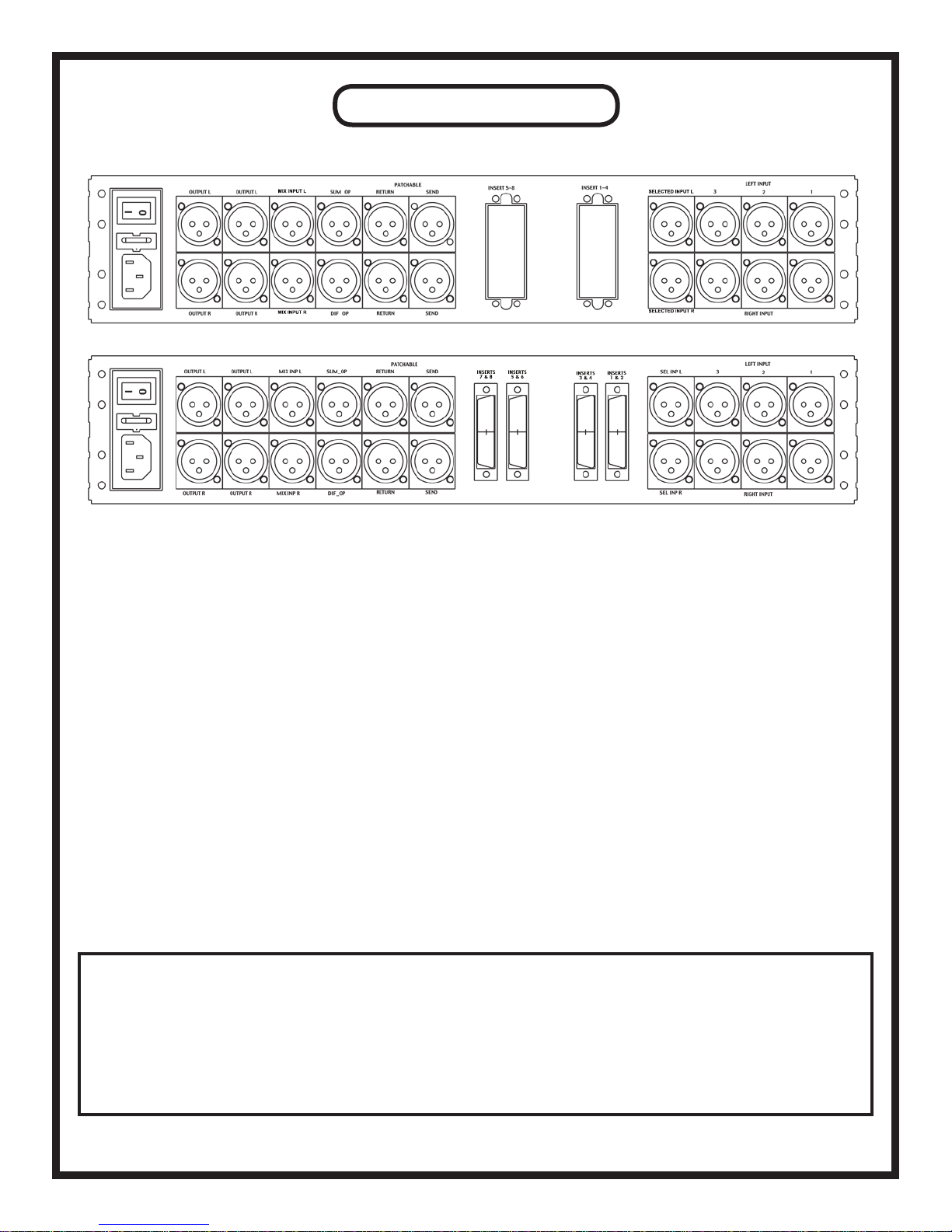
THE BACK PANEL
Top drawing: ELCO conguration Bottom drawing: DB-25 conguration
A B C D E F G H I
A. Power Switch: Where the IEC power cable is inserted, the fuse is placed, and the power is switched off and on. Most
users should be familiar with this feature set.
B. Output L/R (x2): Two sets of balanced outputs, typically going to your favorite A/D converter and a monitor controller/VU
meters.
C. Mix Input L/R: These inputs feed the FADER in MIX mode. See page 15 for more details.
D. SUM-DIF Outputs: The outputs for the raw encoded signals (unprocessed by Inserts 2 & 3). SUM signal is attenuated
6dB, DIF is boosted 6 db to bring them to “normal” levels that are easier for most outboard gear to process.
E. PATCHABLE Sends/Returns: Factory-wired to patch into Insert 6, but internally user-adjustable. See page 18 for details.
F. Inserts 5-8 connectors*: ELCO/DB-25 connectors for the last 4 inserts.
G. Inserts 1-4 connectors*:ELCO/DB-25connectorsfortherst4inserts.
H. Selected Input L/R: The selected input’s dry signal comes out here.
I. Inputs: 3 sets of inputs for whatever you want to plug into the BACKBONE. We recommend audio sources; you can try
plugging in your toaster, but it probably won’t sound very good.
*In the ELCO conguration, two 56-pin ELCO connectors handle all of the inserts. In the DB-25 conguration, four 25-pin
connectors do the same job. For the ELCO pinout, see page 19; for the DB-25 pinout, see page 20.
IF DRIVING ANY UNBALANCED LOADS, READ BELOW:
If you are planning on driving any unbalanced equipment with your BACKBONE, you must make sure
to FLOAT PIN 3. If Pin 3 is grounded, there is a possibility of damaging the BACKBONE, or at
least introducing unwanted noise into the signal path. Lifting Pin 3 will allow you to drive unbal-
anced equipment, but please note that this scenario will lead to a 6 dB drop in level.
This applies to ALL outputs, including those on the ELCO/DB25 snakes.
10
SELECTED INPUT L
MIX INPUT L
MIX INPUT R SELECTED INPUT R
INSERTS
1 & 2
INSERTS
3 & 4
INSERTS
5 & 6
INSERTS
7 & 8

BACK PANEL
Aspreviouslydescribed,youhave3InputXLRspersidefollowedbyanOutputXLRthatreectsthe
chosen input. These are factory set-up as AC coupled (the inputs are protected by capacitors, which may prevent
someclicksorpopswhenswitching),whichimpliesthesignalhastoowthroughcapacitors.Ifthesecapacitors
are unwanted, there are jumpers (no soldering required) to bypass them and provide DC coupled inputs (similar
jumpers exist for the outputs). The diagram describing the jumper locations is on page 23.
Next are Multi-Pin connectors that handle all of the INSERT inputs and outputs. The BACKBONE uses
EDAC/ELCO 56-pin connectors. There is also an option for DB-25 connectors, if one so desires. Both of these
systems are very reliable and allow for pretty bulky audiophile wires that many mastering engineers prefer. Are
these wired to the “industry standard”? Close, but not exactly. The big difference between the industry stan-
dard and what the BACKBONE uses has to do with the XLR “sex”. The standard may have either all male or
all female XLRs, while what you need here is half male, half female. So, worst case scenario, buy one of each
‘standard’cable,andspendanhourortwoswappinghalfoftheXLRs.Bettercasescenario,ndpre-madeones
thattthebill(makesuretothoroughlyinvestigaterst!).Bestcasescenario,haveagoodtechbuildsomeau-
diophile wire (maybe silver conductor) cut-to-length, tailor-made ELCO or DB-25 cables. (ELCO pinout is on p.
19, DB-25 pinout is on p. 20)
If you wish to purchase custom cabling for your setup, we highly recommend Rapco Horizon. If you go to
their website (www.rapcohorizon.com), there is more information on their cables, line testers, and various other
products. They build their cables VERY well, they have excellent customer service, and we’ve found their prices
to be quite reasonable.
Next comes an interesting pair of XLRs marked “PATCHABLE”. There are a number of points internally in
the console where these XLRs can be patched. Of course, this means opening up the BACKBONE, opening up
the manual (which is probably open already if you’re reading this), attempting to interpret the map on page 18,
and moving some ribbon cables, but dealing with ribbon cables seems to be par for the course if you’ve had a PC
in your life. The three intended purposes for these are:
- An alternative to the multi-pins for one pair of inserts. You might use those for “producer-processors” or
new gear you are evaluating. In that case, you probably don’t want to have anything plugged into the corre-
sponding XLRs off the multipins. For example, the Manley factory presets that “PATCHABLE” to INSERT
6, so use either the multi-pin Insert 6 XLRs or these. Actually, just watch out for the female XLRs or inputs
because you don’t want the outputs from two different boxes feeding into each other. The alternative set of
male XLRs can be considered a parallel output, so it can feed something. Which brings us to…
- A feed to the monitor controller for checking the processing half-way into the chain. Typically a master-
ing engineer may want to compare the dry signal (“Selected Input” XLR), the analog processed signal (Main
Output 2), and maybe somewhere part way through the processing, which these jacks allow.
- A feed for some of the unusual processing tricks described in the MIX/FADE section on page 15.
Next on the back panel are outputs for SUM and DIF. These are the raw encoded signals (unprocessed by
Insert 2 & 3). These XLRs could be used to send to processors, in which case probably either but not both would
be used. You can also send these signals to VU meters. **Note that the SUM signal is attenuated 6 dB and the
DIF signal is boosted 6 dB, so that with typical stereo music mixes these outputs have similar levels to normal
left and right signals (easier for outboard gear to process).**
After that, you get MIX INPUTS. These feed the FADER in MIX mode. As described on page 15, if you use
these as a return from processing the DIFF signal (but not the SUM), you should get a special Y cable where the
right XLR is wired out-of-phase. There is a diagram of this cable on page 21.
Last is a pair of stereo outputs. One pair generally goes to your main Analog to Digital Converter and the
other goes to the monitor controller or VU meters.
11

THE GUTZ
GUTZ
There is a 4-deck sandwich arrangement of printed circuit boards that make up the active electron-
ics that process audio. Two long boards are so-called motherboards that hold 5 small PCBs each. There
are separate motherboards for left and right, and the left is the top board, while the bottom takes care
of the right. Each mother has about 36 relays and a dozen connectors, plus about 4 ICs that feed a fake
signal to bypassed inserts. There are a number of connectors on the bottom the motherboards to join
with each other.
The 5 small daughter boards on each mother can be considered gain blocks and there are 10 total.
Each is labeled to its calibrated location but there is some minor inter-changeability for troubleshoot-
ing. For example, on each mother, #1 and #5 (INPUT TRIM, OUTPUT TRIM) can be swapped. #2
and #3 can be swapped as well, but in the case of such a swap you must move the red jumpers off #3
(now in #2’s place) and put them on #2 (now in #3’s place). However, you cannot swap daughter
boards from the bottom to the top mothers because of connector inversions. Because of the precision
calibrations, especially in the SUM-DIF circuits, we advise that after a temporary swap the boards
should go back to their original locations.
If one board or switch develops a problem and needs to be replaced, Manley has a support program
andboardsinstockintendedforswappingintheeld(ratherthansendingtheentireBACKBONEback
to the factory and losing time).
Similarly, front panel boards associated with EAO buttons (which are also on sockets) and Greyhill
switches, back panel boards associated with XLRs and multi-pin connectors and power supply boards
areallonconnectorsandcanbeeasilyeldserviced.TheMasteringswitchershouldbeoperablefor
decades.
Each daughter board has several trimmers and some of them should be tweaked on a routine basis
(like once a year) for best performance. These would be trims associated with gains and DC offset.
About half the trims may rarely need tweaking or perhaps can be left at factory settings and these are
only associated with common mode rejection (hum & buzz immunity). Because the trimming pro-
cedure for the BACKBONE requires special equipment generally not in the hands of end users, we
stronglysuggestleavingthisprocesstotheManleyLabsservicecenter,ortoaqualiedtechnician.
12

SOME THOUGHTS
FROM OUR LAB
**NOTE** We recommend leaving one rack space open above and below your BACKBONE for cooling pur-
poses (as opposed to cooling porpoises, which we don’t know anything about). It’s always good to keep some air
owing around your gear. This helps avoid damage to delicate components, as well as to your delicate hands.
GEAR SEQUENCE
One interesting quality of much analog equipment is the optimum sequence of gear. While there
is some validity to ideas of “EQ before compression” or “EQ after compression”, the practical real-
ity is trickier. For example, Box #1 may seem to sound best only if it drives into another box that does
not have a transformer input – it likes to see a relatively simple load and maybe really shines driving
into just one particular box for unknown reasons. Box #2 may be quite the opposite, and it just loves
to drive a transformer input. So the optimum order may just take a day or two of experimentation and
listening, rather than thinking about the function of the box. This is the biggest single reason for not
including the option which allows one to arbitrarily change the order of processors – there is almost
always an optimum order sound-wise.
While we are on that topic, there are some other interesting and not very obvious potential sequenc-
es of processors. For example, engineers might only consider a brick-wall limiter as appropriate as a
nalornext-to-nalprocess.Andwhilethatisgenerallyagoodplaceforone,youmightndthata
limiter early in the chain helps compressors and de-essers further down from over-reacting and pump-
ing, and might prevent EQs from clipping. We are not suggesting trying it for the sake of an idea, but
suggesting a listening experiment because, in the end, it is more about the particular collection of gear
that you have chosen and the collection of input-output idiosyncrasies that few are aware of. This hints
at why some people hate gear that others love. The “sound” of a processor has to do with what device is
patched to what, and settings of input and output levels. One might hear serious raves about some piece
and expect something dramatic, when it was actually the subtlety of the box that was so sweet, so one’s
expectations play a part in user reviews. And not everybody has the same goals, styles and require-
ments.
SOME SUM-DIFFERENCE MUSINGS
One school of thought suggests we use our gentlest and smoothest processors for mid-side tweaks,
mostly because there can be inherent dangers with moderate alterations of those channels. But this is
mastering, and a few dB of this or that is already verging on drastic, right? The other school of thought
suggeststhatsometimesanarrownotchorsteeplteroneitherthesumordifferencecaneffectively
treatproblemsthatcan’tbexedanyotherway.Perhapsyouwillndthatthesetwoinsertsarebetter
served with your best EQ’s than with dynamic processors. Equalizing in the sum-diff domain relaxes
some of the demands of precise left-right matching.
“WIDTH”
We’ve just talked about how subtle SUM-DIF processing can be very useful. With that said, be
very careful not to mangle the stereo image too much - this is a tool that is often over-used, abused, and
very poorly understood. Certainly you have heard speakers wired out-of-phase and heard a stereo pair
and checked out what happens if one side is phase-reversed. It is not pleasant and can be rather discon-
certing. Increasing the stereo width is employing the same effect but to a lesser degree.
13

“WIDTH” cont’d...
So we’ve all heard some “big” sounds before that result from mid-side tweaks. But did you know
this? Let’s say you increase the width by just 1 dB (which is pretty subtle). What begins with maybe
100 dB dB of separation between left and right diminishes quickly. Now a sound that was panned hard
left will also be on the right side but out-of-phase and down about -20 dB. So, what seems only a hair
wider actually reduced left-right separation from 100 dB to 20 dB. Maybe this could be a concern if
you expect some people will listen on headphones. Maybe mixes with cool dramatic hard panned tracks
might actually LOSE some width along with losing center. Hmmm.
To do what we want, an analog circuit requires that 2 signals get subtracted (and added) accurately,
and this happens twice. It relates to a common spec called “common mode rejection ratio” or CMRR.
In general, good CMRR is spec’d for a low frequency because the numbers are best there and get worse
as the frequency gets higher. For example, a typical op-amp like a MC5534 can claim a best case sce-
nario CMRR of 90 dB at 60 Hz. Looking at the graph, however, that number drops to 40 dB at 20 kHz.
Not very impressive, if we hope for 80 dB across the entire spectrum as a base-line. A typical high
quality resistor may have a tolerance rating of 1% which means it is likely we only get 40 dB of separa-
tion in practice. Even a superb resistor might be 0.1% tolerance which translates to 60 dB. So to make
a long story short, it ain’t easy to get 80 dB of separation from 20Hz to 20KHz in a high performance
sum-diff and back circuit in analog. It is easy in digital when the operations are just a few additions
and subtractions, and 24 bit math virtually guarantees numbers in the range of 144 dB. But these are
just numbers and the previous paragraph suggests that once one actually adjusts or processes sum-diff
signals those numbers quickly become low anyways.
Perhaps some of the feeling that increasing the width is practically necessary in mastering might
be due to a few common modern studio techniques that may accidentally strip some subtle localization
cues. For example, the ear uses the initial onset of transient peaks as well as phase and level differences
as localization cues, and now we have more dynamic processors (compressor plug-ins on every track,
group and mix bus) in more studios than ever before in history. We also have more tracks and denser
arrangements.Wetimeshifttracksandusemorehigh-passlters(messingwithphase).Notthatthese
things are bad, but one should be aware that there are always trade-offs, and some say that “Engineer-
ing is the art of balancing trade-offs”.
14

MORE ON THE MIX/FADE KNOB
Traditionally, mastering engineers used a mix function when cross-fades between two analog tape
machines were used to segue between songs. Now that is much easier done in the workstation. But
in recent years, with the availability of convolution reverb programs and sizable libraries of impulse
responses(IRs)ontheinternet,somemasteringengineersarendingthatatouchofconvolutionreverb
helps gel drier mixes. The effect should not be like “reverb” in the traditional sense but more like a
naturallycomplexavor.Notsurprisingly,themostlikelyIRcandidatesarefastdecayingrealrooms
somewhat on the “dry” side. The bad news is that it can be unpredictable, which IR works best with
each session or even each song, and auditioning IRs can be time-consuming and tedious. In any event,
it is a dangerous technique and one to be used sparingly and subtly, unless the client requests to put re-
verb on a whole mix. But there are plenty of free “colors” to add to your palette if you have the inclina-
tion to experiment on your own time.
There are other possible sources you may want to try. For example, both the sum and difference sig-
nalsappearonthebackpanelXLRsandyoumayndthatyoucandosomereallydramaticequaliza-
tion or compression on either of those and mix it lightly back into the stereo mix, similarly to what was
described in the “Sum-Difference Musings” section earlier. You would need a special XLR “Y” cable
to do this right. This cable would start with a female XLR, with two balanced lines coming out of it to
two male XLRs. VERY IMPORTANT NOTE: One male XLR gets wired conventionally and the other
male XLR needs to be wired reverse phase and that XLR should get boldly marked “RIGHT”. There is
a diagram of this cable on page 21.
Another possibility is introducing a processor that might ordinarily be considered too colored or
distorted for mastering but if mixed in lightly (as opposed to running the full signal through it), can be
brought in under the main signal. This technique may tend to vary dynamically depending on the nature
and depth of the distortion. For example, if it is set up to be a conventional clipping effect, during quiet
passages, there may be no clipping, during moderate levels where there is some clipping, the mixed-in
effectmightseemsignicant.However,withevenhotterpassages,theclippingispreventingthateffect
from gaining more output level, while the dry signal has had no such restraint, so the relative mix will
lean more toward dry. Pre-limiting that color-box can prevent the distortion from becoming too nasty.
Yet another combination that can be excellently mixed in is the limiter-EQ, where you have the
EQ set for drastic high boost or drastic “smiley face” boosted low & highs & dipped mids. What hap-
pens is that as the signal level drops, with this low threshold limiter-EQ, the proportion of “wet” signal
becomesrelativelystronger.Intherstcase,itwouldgivemorehighsandairatlowlevelswithoutbe-
coming harsh and biting once the song gets loud. The second case acts a bit like an automatic Fletcher-
Munson EQ where both highs and lows seem bigger at lower levels (opposite of what our ears normally
do, so it sort of “compensates”) and this happens without the usual drawbacks of just boosting lows and
highs. It is probably best to have the limiter set up to be digging in at relatively lower levels, which is
quite the opposite of typical limiter settings. Note, that normal transients are passed by the “dry” part of
the chain. Also, these kinds of tricks can bring a new motivation for keeping gear that may have been
collecting dust, because it doesn’t require the ultra-high performance that you need for the primary
chain.
For some easy-to-follow parallel processing diagrams, check out Page 23...
15

EXPLORING OTHER USES
We’ve had a few interesting questions regarding different applications of the BACKBONE. Some
customers have decided it would make an excellent teaching tool. The ability to simply and easily dem-
onstrate the importance of gear sequence (especially when making use of the SWAP button) makes the
BACKBONE well-suited for educational purposes. Still others are planning to use their BACKBONE
for tracking needs, rather than the mastering applications for which it was designed.
In terms of tracking, another somewhat more complex use of the BACKBONE has been suggested
by a few people - using it to route three different mics through many different microphone preampli-
ers.Wedidn’tdesigntheBACKBONEforthispurpose,butweDObuildaproductcalledtheManley
MicMAID that is designed to do just that very thing. Check out our website (www.manley.com) for
moreinformation!
As mentioned before, the BACKBONE was not designed for this purpose. Because of the way the
unit’ssignalowisstructured,usingamicpreasaninserthasonemajorcomplication-UNDER NO
CIRCUMSTANCES CAN YOU USE +48V PHANTOM POWER WITH ANYTHING CON-
NECTED TO THE BACKBONE. Turning on +48V on your mic pre would mean sending those 48V
into your BACKBONE, which would potentially (read: “almost certainly”) damage crucial compo-
nents. Also, the BACKBONE was designed for line-level signals, not mic-level ones. Since signal from
a microphone has about 1/100th the level of a line-level one, and the BACKBONE has not been opti-
mized for such a signal, it simply wouldn’t function correctly for this application.
With that said, once a signal has been brought up to line level it can be used in many ways with the
BACKBONE.Tracking,mixing,mastering-useyourimagination!
LABELING YOUR SWITCHES
The EAO switches for each input and insert on the front panel can be labeled, e.g. “EQ #1”,
“COMP #4”, etc... If you desire the label to be on the INSIDE of the button (perhaps slightly more
permanentthanjustastickerontheoutside),weadvisethatyougotoalocalofcesupplystoreand
purchase a P-Touch machine (or a similar label-printing device) and some “black on clear” tape for it.
This will let the light shine through around the letters, enhancing legibility.
To remove the switchcaps, you’ll just need a pair of
pincer-style pliers - you have to be able to grip the top and
bottom sides of the switchcap and pull it away from the
socket. You will notice some small indents on these sides of
the switchcap, which make it easier to remove. Be very gentle
when you grip and pull the switchcap - the more delicate
the pliers, the better. Once you have the switchcap in hand,
you can easily pull out the diffuser by pinching the two tabs
towards each other and pulling away from the clear cover.
Print your label and stick it to this diffuser (observing the
orientation of your lettering so that it is not upside-down and/
or backwards), then put the diffuser back inside the clear
switchcap. Re-installing the switchcap is as simple as pushing
itbackintothesocket.Nowyou’redone!
16

TROUBLESHOOTING
NO POWER, NO LIGHTS, NADA - Probably something to do with AC power. Is it plugged in?
Is the mains voltage set correctly for your country? Also, check the fuse on the back panel. A blown
fuse often looks blackened inside or the little wire inside looks broken. A very blackened fuse is a big
hint that a Very Bad Thing occured. Try replacing the fuse with a good one of the same value and size.
If it blows too then prepare to send the unit back to the dealer or factory for repair. The fuse is a protec-
tiondeviceanditshouldblowifthereisaproblem.Iftheunitworkswithanewfuse,ne.
LIGHTS BUT NO SOUND - First, if you have gear plugged into the BACKBONE’s inserts, take
each one out of circuit by pressing whichever insert buttons are lit to turn them off. Remember, the
BACKBONE’s inserts are wired in series, which means that if one piece of gear is muted AND se-
lected into the signal path, everything after it won’t get any signal, including your speakers. This also
means if you have an empty insert (no piece of outboard gear connected to it at all) and select this insert
on the front panel, your signal will disappear...
Next, try disengaging all of the BACKBONE’s active stages: this means GAINS, SUM-DIF, and
MIX/FADE. If there is a problem with one of these active boards, it could cause signal to disappear or
be otherwise altered.
Also try checking the signal from the output labeled “SEL INPUT” on the rear of the BACKBONE
- this output is hard-wired directly from your selected source. If this is muted as well, you might want
to check your source into the BACKBONE and make sure there’s a signal going in.
***IMPORTANT NOTE*** Your Manley Mastering BACKBONE was designed to interface
primarily with fully balanced equipment. It is happiest that way. It is also ne with recieving
signal FROM an unbalanced unit, but matters are complicated when the BACKBONE tries
to output signal TO an unbalanced unit.
If you intend to use any unbalanced gear with your BACKBONE, you must ensure that Pin
3 is oating, not grounded. Grounding Pin 3 can potentially cause damage to the BACK-
BONE, and will likely introduce unwanted noise into the signal path. By oating Pin 3, you
can safely utilize unbalanced equipment - but remember that in this scenario, signal level
will drop by 6 dB.
(Note: this applies to ALL outputs of the BACKBONE, including the ELCO/DB25 snakes.)
There is one situation where you can always drive an unbalanced input from your BACK-
BONE. Because Insert 8 is positioned AFTER your ouput gains, if your Insert 8 has trans-
former outputs (or idiot-proof transformer-like outputs), that processor would effectively act
as the output amplier and be much more tolerant of unbalanced lines connected to your
BACKBONE’s output XLRs.
All things considered, we recommend sticking with balanced gear after your BACKBONE to
avoid complications.
17

INSERT PATCHING
18
Move these Ribbons to any Pair of Headers (INSERTS 1-8).
Shown is Insert 6 using either (both) Patchable XLRs and ELCO / EDAC Keep This End In Place
Keep This End In Place
RHT
LFT
Interior View of Back Panel
ELCO / EDAC Version
HOW TO PATCH PATCHABLE XLRs
L FE T R BI OB N
R HGI T R BI BON
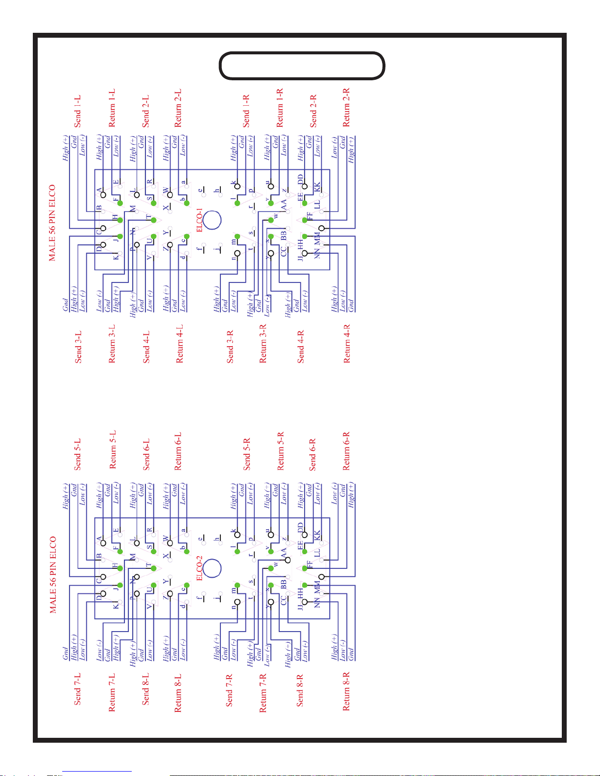
ELCO PINOUT
This diagram is drawn from the
perspective of OUTSIDE THE
UNIT, looking AT THE BACK
PANEL.
19

DB-25 PINOUT
22
HOT
COLD
GROUND
HOT
COLD
GROUND
HOT
COLD
GROUND
HOT
COLD
GROUND
HOT
COLD
GROUND
HOT
COLD
GROUND
HOT
COLD
GROUND
HOT
COLD
GROUND
GROUND
RETURN 3-L
RETURN 4-L
RETURN 3-R
RETURN 4-R
SEND 3-L
SEND 4-L
SEND 3-R
SEND 4-R
24
12
25
10
23
11
21
9
22
7
20
8
18
6
19
4
17
5
15
3
16
1
14
2
13
HOT
COLD
GROUND
HOT
COLD
GROUND
HOT
COLD
GROUND
HOT
COLD
GROUND
HOT
COLD
GROUND
HOT
COLD
GROUND
HOT
COLD
GROUND
HOT
COLD
GROUND
GROUND
RETURN 5-L
RETURN 6-L
RETURN 5-R
RETURN 6-R
SEND 5-L
SEND 6-L
SEND 5-R
SEND 6-R
24
12
25
10
23
11
21
9
22
7
20
8
18
6
19
4
17
5
15
3
16
1
14
2
13
HOT
COLD
GROUND
HOT
COLD
GROUND
HOT
COLD
GROUND
HOT
COLD
GROUND
HOT
COLD
GROUND
HOT
COLD
GROUND
HOT
COLD
GROUND
HOT
COLD
GROUND
GROUND
RETURN 7-L
RETURN 8-L
RETURN 7-R
RETURN 8-R
SEND 7-L
SEND 8-L
SEND 7-R
SEND 8-R
24
12
25
10
23
11
21
9
22
7
20
8
18
6
19
4
17
5
15
3
16
1
14
2
13
HOT
COLD
GROUND
HOT
COLD
GROUND
HOT
COLD
GROUND
HOT
COLD
GROUND
HOT
COLD
GROUND
HOT
COLD
GROUND
HOT
COLD
GROUND
HOT
COLD
GROUND
GROUND
RETURN 1-L
RETURN 2-L
RETURN 1-R
RETURN 2-R
SEND 1-L
SEND 2-L
SEND 1-R
SEND 2-R
24
12
25
10
23
11
21
9
22
7
20
8
18
6
19
4
17
5
15
3
16
1
14
2
13
INSERTS 1 & 2 INSERTS 3 & 4
INSERTS 5 & 6 INSERTS 7 & 8
Table of contents
Popular Music Mixer manuals by other brands

Pioneer
Pioneer DJM-850-K operating instructions

Yamaha
Yamaha DM 2000 Version 2 Software installation guide

Pioneer
Pioneer DJM-900SRT operating instructions

Etabeta electronics
Etabeta electronics NT Series operating instructions

ALLEN & HEATH
ALLEN & HEATH Xone:K2 user guide

Behringer
Behringer EURORACK UB1204-PRO user manual


