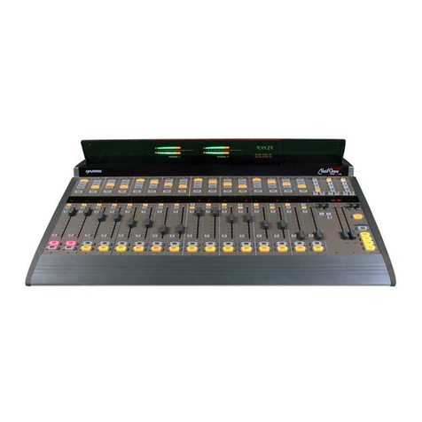
Harris Gatesway II User manual

www.SteamPoweredRadio.Com
•
•
·•
WARNING
THE
CURRENTS
AND
VOLTAGES
IN
THIS
EQUIPMENT
ARE
DANGEROUS.
PERSONNEL
MUST
AT
ALL
TIMES
OBSERVE
SAFETY
REGULATIONS.
This
manual
is
intended
as
a
general
guide
for
trained
and
qualified
personnel
who
are
aware
of
the
dangers
inherent
in
handling
potentially
hazardous
electrical/electronic
circuits.
It
is
not
intended
to
contain
a
complete
statement
of
all
safety
precautions
which
should
be
observed
by
personnel
in
using
this
or
other
electronic
equipment.
The
installation,
operation,
maintenance
and
service
of
this
equipment
involves
risks
both
to
personnel
and
equipment,
and must be performed
only
by
qualified
personnel
exercising
due
care.
HARRIS
CORPORATION
shall
not
be
responsible
for
injury
or
damage
resulting
from
improper
procedures
or
from
the
use
of
improperly
trained
or
inexperienced
personnel
performing
such
tasks.
During
installation
and
operation
of
this
equipment,
local
building
codes
and
fire
protection
standards
must be
observed.
The
following
National
Fire
Protection
Association
(NFPA)
standards
are
recommended
as
references:
-Automatic
Fire
Detectors,
No.
72E
Installation,
Maintenance,
and Use
of
Portable
Fire
Extinguishers,
No.
10
-
Halogenated
Fire
Extinguishing
Agent
Systems,
No.
12A
WARNING
ALWAYS
DISCONNE
CT
POWER
BEFORE
OPENING
COVERS,
DOORS,
ENCLOSURES,
GATES,
PANELS
OR
SHIELDS.
ALWAYS
USE
GROUNDING
STICKS
AND
SHORT
OUT
HIGH
VOLTAGE
POINTS
BEFORE
SERVICING.
NEVER
MAKE
INTERNAL
ADJUSTMENTS,
PERFORM
MAINTENANCE
OR
SERVICE
WHEN
ALONE
OR
WHEN
FATIGUED.
Do
not
remove,
short-circuit
or
tamper
with
interlock
switches
on
access
covers,
doors,
enclosures,
gates,
panels
or
shields
. Keep away from
live
circuits,
know
your
equipment and
don't
take
chances.
WARNING
IN
CASE
OF
EMERGENCY
ENSURE
THAT
FOWER
HAS
BEEN
DISCONNE
C
TED.

www.SteamPoweredRadio.Com
Treatment
of
Electrical
Sho
ck
1.
If
victim
is
not
re
spo
ns
iv
e
follow
the
A-B-Cs
of
basic
life
s
upport.
PLACE
VICTIM
FLAT
ON
HIS
BACK
ON
A
HARD
SURFACE
®
AIRWAY
IF U
NC
ONSCIOUS,
OPEN
AIRWAY
LIFT
UP
NECK
PUSH
FOREHEAD
BACK
CLEAR
OUT
MOUTH
IF
NECESSARY
OBSERVE
FOR
BREATHING
CHECK
CAROTID
PULSE
IF
PULSE
ABSENT,
BEGIN
ARTIFICIAL
CIRCULATION
®
CIRCULATION
®
BREATH
I
NG
IF
NOT
BREATHING
,
BEGIN
ARTIFICIAL
BREATHING
TILT
HEAD
PINCH
NOSTRILS
MAKE
AIRTIGHT
SEAL
4
QUICK
FU
LL
BREATHS
REMEMBER
M
OUTH
TO
MOUTH
RESUSCITATION
MUST
BE
COMMENCED
AS
SOON
AS
POSSIBLE
DEPRESS
STERNUM
1 l/2"TO
2·
APPROX
{ONE
RESCUER
' 15
COMPRESSIONS
ao
SEC
. 2
QUICK
BREATHS
APPROX
.
{TWO
RESCUERS
bO
SEC
5
COMPRESSIONS
' 1
BREATH
NOTE:
DO
NOT
INTERRUPT
RHYTHM
OF
COMPRESSIONS
WHEN
SECOND
PERSO
N IS
GIV
IN
G
BREATH
Call
for
medica
l
ass
i
stance
as
soon
as
possible.
2.
If
victim
is
responsive.
a.
keep
them
warm
b.
keep
them
as
quiet
as
possible
c. l
oosen
their
clothing
(a
reclining
position
is
recommended)
•
•

www.SteamPoweredRadio.Com
•
•
•
FIRST-AID
Personnel
engaged
in
the
installation,
operation,
maintenance
or
servicing
of
this
equipment
are
urged
to
become
familiar
with
first-aid
theory
and
practices
. The
following
information
is
not
intended
to
be
complete
first-aid
procedures,
it
is
brief
and
is
only
to
be
used
as
a
reference.
It
is
the
duty
of
all
personnel
using
the
equipment
to
be
prepared
to
give
adequate
Emergency
First
Aid and
thereby
prevent
avoidable
loss
of
life.
Treatment
of
Electrical
Burns
1,
Extensive
burned
and
broken
skin
2.
a.
Cover
area
with
clean
sheet
or
cloth.
article.)
(Cleanest
available
cloth
b.
Do
not
break
blisters,
remove
tissue,
remove
adhered
particles
of
clothing,
or
apply
any
salve
or
ointment.
c .
Treat
victim
for
shock
as
required
.
d.
Arrange
transportation
to
a
hospital
as
quickly
as
possible
,
e.
If
arms
or
legs
are
affected
keep them
elevated.
NOTE
If
medical
help
will
not
be
available
within
an
hour
and
the
victim
is
conscious
and
not
vomiting,
give
him a weak
solution
of
salt
and
soda:
1
level
teaspoonful
of
salt
and
1/2
level
teaspoonful
of
baking
soda
to
each
quart
of
water
(neither
hot
or
cold).
Allow
victim
to
sip
slowly
about
4
ounces
(a
half
of
glass)
over
a
period
of
15
minutes,
Discontinue
fluid
if
vomiting
occurs.
(Do
not
give
alcohol,)
Less
severe
burns
-
(1st
& 2nd
degree)
a.
Apply
cool
(not
ice
cold)
compresses
using
the
cleanest
available
cloth
article.
b.
Do
not
break
blisters,
remove
tissue,
remove
adhered
particles
of
clothing,
or
apply
salve
or
ointment.
c.
Apply
clean
dry
dressing
if
necessary.
d.
Treat
victim
for
shock
as
required.
e.
Arrange
transportation
to
a
hospital
as
quickly
as
possible
.
f.
If
arms
or
legs
are
affected
keep them
elevated
.
REFERENCE:
ILLINOIS
HEART
ASSOCIATION
AMERICAN
RED
CROSS
STANDARD
FIRST
AID
AND
PERSONAL
SAFETY
MANUAL
(
SECOND
EDITION)

www.SteamPoweredRadio.Com
•
••
MAINT
ENANCE SUPPLEMENT
Att
enuator
Cl
eani
ng
Instructi
ons
1. U
se
lint
free cloth
or
Kem
-Wir>es
when
clc,:ming
or lubricating
att
en
uator
s.
U
se
each
cloth once
and
discard.
2. U
se
denatured alcohol
as
a cleaning
agent.
WA
RNING: DO
NOT
use carbon tetrachloride.
It
causes
noise
and
the fumes
may
cause injury
to
personnel.
3. U
se
a soft
clean
pencil
eraser
to
remove spots
or
noisy
are
as
not
cleaned
in
Step
2.
4. Lubricate
with
a pure, high
grade
vaseline.
5.
Clean
and lubricate
each
control on a regular schedule.
Thi
s function should
be
perform
ed
every 50,000 cycles
of
operation or every three months, whichever occurs first.
/

www.SteamPoweredRadio.Com
/
ADDENDUM
CAUTION -
To
prevent
severe
ground loops, all wiring connected
to
this console must
be
free from ground connections in the source
and
load equipment (microphones,
turntables, tape players, recorders,
speakers,
etc.).
An
ohmmeter check
is
necessary
to
be
certain that
each
wire
is
not
grounded before connecting
it
to
the console.
If
any source
or
load equipment
has
a grounded connection wire,
an
isolating trans-
former must
be
used
between that equipment
and
the console.
A final ohmmeter check
is
recommended:
After
all system connections are made,
temporarily disconnect the station ground
from
the console
and
measure
the resistance
(ohms) from the console ground stud to the station ground. A very high resistance
is
normal - a
low
reading indicates a ground loop.
All
ground loops must
be
eliminated
before operating the console.
Be
sure
to
re-attach the station ground
to
the console
after testing.
1-1
5-7
1
f •
Gates Rudio Company
Quincy, Illinois

www.SteamPoweredRadio.Com
/
TABLE
OF
CONT
E
NTS
• PAGE
••
SPECIFICATIONS ....................................................................................................
ii
INTRODUCTION ...................................................................................................... 1
I
NSTALLAT
ION........................................................................................................ 1
A.
Unpacking Instructions ...
......
...................................................................
..
1
B.
Audio System Installation Information ..................................................... 2
C.
Installation Procedure ................................................................................ 2
1. Power Connections ............................................................................ 2
2.
Warning Lights.................................................................................... 2
3. Input Connections to Console ............................................................ 2
4. Output Connections
to
Console ........................................................ 3
OPERATION ............................................................................................................ 4
a.
Ga
in Adjustment ................................................................................ 5
b.
Cue
-Intercom System ........................................................................ 5
MAINTENANCE...
..................................................................................................... 6
Troubleshooting ........................................................................................ 6
Troubleshoot
ing
Guide ...............................................................:.............. 6
Special Conditions .......'............................................................................. 7
ACCESSORIES .................
.'....
......
...
..
.....
....
.
..
..
......
.....
..
..
......
..
..
......
..
...............
..
......
..
7
MUTING CIRCUIT
DIAGRAM
& REASSIGMMEf\JT INSTRi_tCTIONS
..
".
.... ........... 8
TAB
LE 1 ............................................................:.........................................:..........:.. 9
PARTS LIST
L
OSS
PAD CHART
SPEAKER MATCHING TRANSFORMER
DIAGRAMS
A.
Amplifier Schematics
B.
Composite Drawings
C.
System Block and Schematic
I •
.j.
Gatesway
II

www.SteamPoweredRadio.Com
'
/
SPECIFICATIONS
MICROPHONE TO
REGULAR
PROGRAM
LINE
OUT
Maximum Gain:
Response:
Distortion:
Noi
se:
Crosstalk:
MEDIUM
LEVEL
INPUTS
100 dB
±2
dB·at 1,000
Hz
±1.0 dB from 20
to
20,000
Hz
0.5%
or
less
from 20
to
20,000
Hz
at
+18
dBm
out
64 dB below
+8
dBm
output
with
-60
dBm
output.
The equivalent input noise
is
-124
dBm
or
better.
(20
to
20 kHz) 3 dB points
In
the
noise
with
normal levels and control positions
(Remote, Tape, Net
and
Turntable Inputs
to
Regular Program Line Out)
Maximum Gain:
Response:
Distortion:
Noise:
MONITOR CIRCUITS
Maximum Gain:
Response
:
Distortion:
POWER
REQUIREMENTS
Primary Power:
MECHANICAL
SPECIFICATONS
Console:
Transformer Panel:
I •
60 dB
±2
dB at 1,000 Hz
±1.0 dB
from
20
to
20,000
Hz
0.5%
or
less
from
20
to
20,000
Hz
at +18
dBm
output
64 dB below
+8
dBm
output
with
-20
dBm
input
118 dB
+2
dB
Mic-.A
.ud
to
monitnr
out
132dB
±2
dB
from
Mic-Pgm
to
monitor
out
57 dB
+2
dB from Ext
to
monitor
out
±1
dB
from
20
to
20,000
Hz
at
+30 dBm
1%or
less
from 20
to
20,000
Hz
at
+40 dBm
(10 watts)
105/125volts RMS, 50/60cycl
es
40 watts (approximately)
48-¼"
wide, 17" deep,
8-3/4"
high
5"
x
19"
Panel, overall depth
.
jj
. Gatesway 11

www.SteamPoweredRadio.Com
•
•
/
INTRODUCTION
T
he
Gatesway 11console
is
a monophonic console providing all the
necessary
function$
and
facilities
for
the
AM
or
FM station that broadcasts monophonic programs. The console
is
capable
of
feeding a flat
response
signal
to
the line
or
by
switching a program equalizer
into
t
he
circuit, the
response
may bealtered for special effects
or
linecorrection.
T
he
first
three channels
are
microphone input channels. lnl')ut switching
is
provided for
control room
and
studio microphone
feeds.
Channels four, five, six,
seven,
and eight
are
medium level inputs
used
for turntable, tape, network, and remote programming.
All medium
level
inputs except network and remote
are
switchable into
two
separate input
channels.
T
he
monitor amp input
is
switchable into three sources. These are audition
buss
output,
program line
and
external mon
itor
input. Headphone monitoring
is
provided
by
an
external
jack plate mounted at a location suitable to the
user.
A phone selector switch for the above
jack
is
provided
for
program, cue, network,
and
external input monitoring.
In
addition, a
phone jack
is
located on the right
end
of
the console and connected
to
the
output
of
the
m
onitor
amplifier.
INSTALLATION
A.
·uNPACKING INSTRUCTIONS
The console
is
shipped in
sevE::rai
boxes
or
cartons. Ti,e
fu:iuwi11g
main
ite111s
wiii
bt
enclosed:
1.
Gatesway
11
Console
with
all amplifiers installed.
2.
Transformer
Panel.
3.
Decal Kit.
4. Stick-on Labels.
5.
Instruction Book.
6.
Four Speaker Transformers.
The shipping container should
be
unpacked carefully
and
inspected for shipping
damage.
If
damage
is
found, contact the shipper immediately.
After
he
has
approved
the
damage
report, which indicates he
will
accept
your
billing for the
damage,
order
new parts from Gates Radio Company. Our billing
of
these
parts plus transportation
expense
will
be
your
claim
to
the Transportation Company.
The Gatesway
11
Console
is
covered under the Standard Gates Warranty, a copy
of
which may
be
had on request from Gates Radio Company, 30th
and
Wisman
Lane,
,Quincy, Illinois 62301. ·
8.
AUD
IO SYSTEM
INSTALLATION
INFORMATION
Before any actual installation
is
started, the following points should
be
studied
care-
fully, physical location of all components should
be
decided
and
cable routing should
be determined. Only after
these
plans
have
been
completed, may installation
be
made
in
an
orderly manner.
-1-
Gat
esway
11

www.SteamPoweredRadio.Com
The transformer panel
is
5-
1
/4"
x
19"
and
can
be
rack mounted.
If
desired,
it
may
be
mounted in a small wall box
or
under the
base
of
a desk. Ample ventilation must
be
provided since the
unit
generates son,e heat.
When
rack mounted, the p,mel
is
designed
for
natural convection cooling.
If
the ambient temperature
of
the rack
is
below 50o
C.
(122°
F.),
the rack does
not
need
forced air ventilation.
Cable routing
or
external connections
of
various signal levels
is
of
prime importance.
T
he
low
level mic input cables should
be
cabled separate from all the other
level
cables.
If
it
is
necessary
to
use
cables
of
diff
erent levels in a common conduit, the difference
between the lowest and the highest level in the
two
cables should not
be
greater than
40 dB.
Physical isolation
is
the
best
way
to
avoid trouble between parallel
cables.
Six inches
or more
spacing
is
preferred.
The console grounding system
is
based
on the one point ground. Different circuit
grounds
are
insulated from the
chassis
and
go
directly
to
the ground STUD located at
the left
end
of
the cabinet. Connect the station ground
to
the cabinet ground stud.
External grounds connected to circuit grounds in the console
will
destroy this system.
A shield ground
buss
is
provided beside both the input and
output
terminal blocks
of
the console.
All
incoming
and
outgoing shields must
be
connected
to
these
busses.
C.
INSTALLATION
PROCEDURE
1.
Power Connections
See
installation drawing No. 852-6264-001 at r
ear
of
this book.
Input power connections
are
made on the
t1ansforr11E:.-
panel block
rBX-2:.
Terminal 1
for
117 volts AC
RMS
and Terminal 2
for
117 volts common.
In
terconnecting power
cables,
between console
and
transformer
panel
are
supplied
with
the transformer panel. Connections
can
be
made
by
following
wire color code shown on Installation Drawing.
2. Warning Lights
117 V AC
for
the warning lights should
be
connected
as
follows:
Terminal
Nos.
TBX1-7
and
TBX2-2
are
for the control room warning lights.
Terminal
Nos.
TBX1-8
and
TBX2-2
are
for
Studio A warning lights.
Terminal
Nos.
TBX1-9
and
TBX2-2
are
for
Studio B warning lights.
Warning light circuits should not
be
grounded at any point and should not draw
more than 2
amps
of
current.
3.
In
put Connections
to
Console
a.
See
installation drawing No. 852-6264-001
at
rear
of
this book.
b.
A shield ground
buss
is
provided beside the input terminal block
of
this
console. All incoming shields must
be
connected
to
this
buss.
Gatesway
II
Twisted shielded pairsare
to
be
used
for all circuits, balanced
or
unbalanced.
The shields
are
to
be
grounded at the shield
buss
in the console
and
nowhere
else.
-2·
...
4
,•

www.SteamPoweredRadio.Com
/
Channel
ONE
has provisions
for
two
different
microphone
inputs.
Front
panel
switching
is
provided.
Channel TWO has provisions
for
two
different
microphone
inputs.
Front
panel
switching is provided. ·
Channel
THREE
has provisions
for
two
different
microphone inputs.
Front
panel
switching is provided.
Channel
FOUR
has
provisions
for
four
different
turntable
inputs.
Front
panel
switching is provided.
Channel
FIVE
has provisions
for
any
of
the
same
four
turntables
inputs
that are
available
to
Channel
FOUR.
Front
panel switching
is
provided.
Channel
SIX
has provisions
for
four
different
tape inputs.
Front
panel switching
isprovided.
Channel
SEVEN
has provisions
for
any
of
the
same
four
tape
inputs
that
are
available
to
Channel SIX.
Front
panel switching
is
provided.
Channel
EIGHT
has provisions
for
three
different
remote
inputs
or
a
network
i
nput.
Front
panel switching is provided.
For
operating impedances, levels, modes, and
other
associated
information,
see
Table 1, page 9.
Turntable
and tape
inputs
are unbalanced and
the
common
si
de
is grounded.
Therefore,
only
use
circuits
with
ungrounded
outputs.
If
the
external source
has an
,_,nba!?nced
outp•.•t. an isolation
transformer
s11ch
as
Gr1tes
A-?1
m11~
he
used.
4.
Output
Connections
to
Console
a.
See
installation drawing
No.
852-6264-001
at
rear
of
this
book.
b.
A shield
ground
buss is provided beside
the
output
terminal
block
of
this console.
All
outgoing
shields must be connected
to
this
buss.
Do
not
ground
them
at
any
other
point.
Th
e
output
line cables
from
this
console are
medium
level and should be routed care-
full
y
to
prevent crosstalk back
into
low
level
input
circuits.
All
speaker
wiring
is high level and must be
run
in
separate
conduit
away
from
low
level
program circuits.
Monitoring
is provided
for
all studios
as
well
as
external
lobby
speakers.
45
to
16/8/4
ohm
speaker matching transformersare supplied
for
matching 16, 8,
or
4
ohm
speakers
to
the
output
of
the
monitor
amplifier.
Because
of
the Remote Lines, the
Talk-
back
circuits
and
Intercom
speakers must be 600 ohms. This is accomplished
by
using a
600
to
1
6/8
ohm
transformer at
the
external
In
tercom
speakers. Speaker connections are
shown
in
the
Installation
Drawing.
The
muting
has been pre-assigned
as
indicated
on
the
Block
Diagram and shown
on
Page
8.
For
re-assignment
of
muting
see
Page
8.
Th
e earphone jack
for
both
the
cue
-intercom and the line
monitoring
circuits
is
mounted
externally
on a jack panel.
The
panel should be mounted
in
a convenient location
in
the
ro
om
and shielded twisted pairs should be used
to
connect
to
the console.
See
Ir:istallation
Drawing.
-3-
Gatesway II

www.SteamPoweredRadio.Com
/
OPERATION
On
the upper left
side
of
the
pa
n
el
above channel mixer 1, 2, and 3
are
three switches.
These
switches perform input switching functions for
each
channel. This selector switch
is
used
to
switch between microphones in two studios. With the lever key
of
channels 1,
2,
and
3 in program position, the microphone preamp
feeds
the program
buss
or the audition
b
uss
with
the lever key in audition position.
The four medium
level
switches, above mixers 4
and
5,
select the desired input
to
each
mixer.
When
the input switches, above mixer 4, are in the
"OFF"
position, the inputs
are
normall
ed
through
to
the mixer 5 switches.
When
any
of
the switches in channel 4
are
switched
"ON",
the input
will
appear at the
output
of
mixer 4. Moving the channel 4 mixer
l
ever
key
to
the program position
will
bring up the medium
level
input on the program
buss.
Moving the desired input switch
to
the
"ON"
position, above mixer
5,
will
switch the
desi
r
ed
turntable
or
tape
into
this mixer. Switching
is
arranged
so
that aturntable
or
tape
cannot be
s,witched
into mixer
5,
if it
is
already switched
into
mixer 4. This prevents
loading the turntable or tape
output
by
paralleling
it
into
two
console inputs. Cueing
facilities
are
provided
for
by
turning either mixer fader
fully
counterclockwise. This con-
n
ects
the turntable
or
tape into the cue-intercom amp. Cueing
can
be
accomplished by
using
the
panel
mounted
speaker
or
headphone (plugged
into
the phone jack). The above
explanation
is
also valid
for
channel 6
and
7.
When
the lever key
is
switched
to
program
position, the desired turntable
or
tape is fed
into
the program
buss.
T
he
first three
leve
r switches, located above mixer
8,
control three remote inputs. The
remote switches provide talkback
and
cueing facilities
to
the remote operator. In the
center position, the remote operator
rec~ives
the program
cue
signal
from the monitoring
amplifier. This
signal
is
fed back
to
the remote operator
to
allow
him
to
start his program
at the proper time. The lower position
is
the
"MIX"
position
and
connects the remote
program
into
the program
buss
through mixer
8.
The upper position
of
the switches
have
a
terminating
load
for
the remote lines
and
provides talkback-functions. The remote lines
are
not tied together when any
or
all
of
the remote keys
are
in the talkb?ck r.ositi0n.
The network input
is
connected
to
mixer 8 when the net input switch
is
in the
"MIX"
position. Preview monitoring
of
the network
is
provided by either turning the mixer control
fu
lly
counterclockwise into the
"CUE"
position
or
rotating the cue selector switch
to
the
net position.
T
he
monitor input selector
is
located on the lower center
of
the panel. Input switching
allows monitoring
of
the audition program,
or
external
signal
source.
The gain
of
the monitor amplifier
is
controlled
by
the gain control located just below the
monitor input selector. ·
The program equalizer
is
located below the VU meter on the lower center section
of
the
panel. The lever switch in the center
is
used
to
switch_the equalizer into the program
circuit either continuously
or
momentarily. The rotary switch on the left
is
used
for
boost
or
roll-off
of
the low frequencies. A maximum
of
approximately 10 dB
of
boost or roll-off
can
be
obtained in 5 equal
steps
at 100
Hz.
The rotary switch on the right
is
used
for boost
or
roll-off
of
the high frequencies. A maximum
of
10 dB
of
boost
or
roll-off
can
be
ob·
t
ained
in 5
equal
steps
at 10,000 Hz. With both rotary switches in the
zero
position, no
boost
or
roll-off
will
be
obtained
and
the
response
shall be flat from 20
to
20,000 Hz.
Gatesway II .4.

www.SteamPoweredRadio.Com
a.
•
b.
/
Gain Adjustment
For
proper level and gain Ddjustmcnt
each
of
the channel mixers shall be turned
out
16
dB
(approximately 1 O'Clock). . Then the master gain
control
can
be adjusted for
0
VU
indication
on
VU
meter. Themastergain
control
is
located
on
the upper center
section
of
the
panel.
All
of
the equipment feeding the console shall have
un
output
level that corresponds
to
the
input
level shown
on
the block diagram.
Cue-Intercom System
The cue controls are located
on
the lower center section
of
the panel.
A cue-intercom input selector switch
is
provided
with
input
positions. The
first
position (net)
is
used
for
monitoring
the
input
network line. Talkback
is
not
possible
in the
network
position. Next, the remote 1, 2, and 3 positions
tie
the cue-intercom
amp
to
the
1,
2,
or
3 remote lines.
For
talkback facilities, the intercom selector
is
switched
to
the desired remote line and the appropriate remote input switch
is
placed
in the
"TB"
position. The incoming remote signal
will
then be heard in the panel
mounted speaker. When the
control
room operator desires
to
talk
out
on
the remote
line,
he
simply pushes the
red
"TALK"
button
in the center
of
the panel and speaks
into
the
panel speaker.
"ST-A"
and
"ST
-B"
positions
allow
listening and talkback
into
Studios A
and
B
if
intercom units have
been
installed in them.
Turntable
and
tape cueing circuits are connected
directly
to
the
input
of
the cue-
intercom amp and may be
used
regardless
of
the position
of
the cue-intercom input
selector. However, in
the
"CUE"
position nothing
else
is
connected
to
the input.
The cuP.-intercom speaker r.n the cc:.;;olo
i:;
set
up
to
be muted
hv
the
ch::in:-;c!
1
!c·.,cr
key, however,
this
muting
does nu( disable
lhe
cue phone jack.
so
it
is
stiil
µussibic::
to
cue a record
by
monitoring the cue
circuit
with
headphones.
Another
headphone jack
is
located on the right end
of
the console cabinet. This jack
is
connected
to
the
monitor
output
for
headphone monitoring.
Speaker muting
is
accomplished
by
using a solid state
muting
circuit
and
no
relays are
used
for
muting. Solid state muting
is
very fast and the chance
of
feedback between
monitor
speaker and microphone
is
very small. •
-5-
Gatesway
11

www.SteamPoweredRadio.Com
•
MAINTENANCE
TROUBLESHOOTING
When
troubleshooting,
it
may
be
necessary
to make voltage measurements,
these
are given
on the schematic diagrams
of
the variousamplifiers. It
is
recommended that, after the con-
sole
is
installed and operating satisfactorily,
these
readings should
be
checked
and
recorded
on the schematic. This
will
provide the station engineer
with
a record
of
the actual voltage
r
eadings
in his installation, using his meter.
If
trouble later develops,
he
will then
be
better
able
to
j
udge
whether
or
not a particular circuit
is
operating properly since
he
will
have
available a record
of
the various readings
of
his particular equipment. DC readings
.......ere
taken
with
a 20,000 ohm/voltmeter
as
indicated on the schematic.
RMS
signal voltages
are
shown in parenthesis
and
must be
measured
with
a vacuum tube voltmeter.
If
a
VTVM
is
used
to
measure
DC voltages, slightly higher readings may
be
obtained.
T
RO
UBLESHOOTING GUIDE
1. No indication on the
VU
meter
and
the
monitor
only
operates from the audition
channel and the external input.
a.
Interchange the program amp
with
monitor amp.
b. Check
for
33 volts between terminals 3
and
5
of
the booster board
and
terminals
3
and
9
of
the output board.
2.
No signal on the program
output
line but indication on the
VU
meter.
a.
Check external cable connections
on
TB-2.
b. Check S18
and
output
pad
board.
3.
No signol
can
be
heard from anv
of
the
rno11it.or
speak-er<:
bl11
thP. prngrnm r.h,mnel
operates O.K.
a. Interchange the
monitor
amp
with
the program amp.
b. Check
for
33
volts between terminals 3
and
5
of
the booster board and 43 volts
between terminals 3
and
9
of
the
output
board.
4. No
signal
can
be
heard from the
cue
speaker.
a.
Interchange the
cue
amp
with
either the program
or
monitor
amp.
b.
Check
for
33
volts between terminals 3
and
5
of
the boosterboard and terminal
3 and 9
of
the
output
board.
c.
Chec
k cue
speake
r.
5.
No indication
can
be
seen
on the
VU
meter when talking into the control room
or
studio microphones but the medium level channels operate O.K.
a. Interchange preamps
if
only
one channel shows no indication.
b.
Check
for
33
volts between terminals 7
and
8.
c.
Check contacts on switch S1.
d. C
hec
k cable terminations on TB1
an
d microphone.
6. No indication
can
be
seen
on the VU meter when
feed
i
ng
one
of
the medium level
inputs.
a.
Ch
eck t
he
in
put
switch, the channel mixer, and program/aud
ition
love
r key.
Gatesway II -6-
/

www.SteamPoweredRadio.Com
/
7. The
control
room
or
studio monitors wi
II
not
operate
but
the
lobby
speakers operate
O.K.
a.
Check
for
33
volts betwe
en
terminals 7
and
9
of
power sapply 3.
b.
Check contacts on switches S
1,
S2,
S3,
S24, S25, and S26.
c.
Check
each
transistor
on
both the muting module boards.
8. Headphones
will
not
operate when plugged
into
headphone
monitor.
a.
Check the contacts
on
switch S33 and the phone jacks.
b. Check the headphones.
9. Talkback
circuit
will
not
operate
but
the cue
circuit
operates O.K.
a.
Check relay K1.
b. Check the contacts
on
switch S34.
c. Check
each
transistor
on
the muting module boards.
d. Check the studio talkback
speakers.
SPE
CIAL
CONDITIO
NS
When
servicing the muting modules
it
may be necessary
to
repla
ce
the 40310 transistors.
If
so,
just any ordinary 40310 transistor cannot be
used.
This transistor
can
be
supplied
by
Gates
or
selected
from
your
own
stock. This transistor shall
have
an
I
EBO~
10
uA
at
V
EB=
15 volts.
If
a transistor
with
a higher IEBO
is
used,
then muting
will
not
occur
at
higher
output
levels.
ACCE
SS
ORIE
S
Th
e Gatcswuy
11
Con:;ole
ha:;
a provision to add a rernot~ Ohl/OFF
<.:011trui
Lu
1nic1u;.,i1u11e
channel No. 2.
If
the user desires
to
install this control, he
rnc1y
order
it
lrurn
Gate5 by
specifying
an
Announcer Remote
ON/OFF
Relay
Kit,
M-6565.
The medium level inputs
of
the Gatesway
11
Console are 150 ohm unbalanced.
If
a balanced
input
or
another input impedance (50
or
600 ohms)
is
desired a line matching
and
isolation
transformer may be ordered
from
Gates. Order Gates 478-0278-000 transformer and
358-0893-000 mounting bracket.
The external intercom speakers must
be
600 ohms. These are available from Gates
by
order-
ing the M-6424 Studio Cue-Intercom Speaker Unit. Order one
unit
for
each
studio position.
The 600
to
45 ohm transformer (only)
is
available
as
Gates 478-0274-000.
-7· Gatesway
II

www.SteamPoweredRadio.Com
'
/
MUTING CIRCUIT
DIAGRAM
ANO REASSIGNMENT INSTRUCTIONS
The Gateswny II Console employs solid state muting
and
is
so
designed
that
it
can
be
selected.
Muting occurs when the current path .
is
opened. Tie strips
TS-10, TS-11,
and
TS-12
are
located on the front
panel
above
each
of
the microphone input selector switches.
Figure 1
shows
the muting
as
wired at the foctory. Channels
1-A,
2-A.
and
3-A
will
mute
studio A, channels
1-B
and
2-B
will
mute studio
B,
and
channel
3-8
will
mute the control
room. .
688
+31:5V
TS-I
I
69R
TS-12
MUTE
B
I
A A
698
MUTE
A
B B
68R
MUTE
CR
CHANNEL
I
CHANNEL
2
CHANNEL
3
FIG. 1
Figures 2
and
3 show examples where other reassignment
is
required.
EXAMPLE 1:
Suppose
it
is
desired
to
change
the muting
so
that channels
1-A
and
2-A
will
mute studio A. channels
1-8
and
3-A
will
mute studio 8,
and
channels
2-8
and
3-B
wilt mute the control room. Figure 2
shows
the correct wiring
to
accomplish this.
68B
TS-10
A
B
CHANNEL
I
EXAMPLE 2:
CHANNEL
I
Gatesway
11
T
8
TS-II
A
CHANNEL
2
FIG. 2
691!
' - +3!.
5V
(j) TS-
12
MUTE
A
A
69R
MUTE
8
B
68R
M
UTE
CR
CHANNEL
3
Channel
1-A
to
mute the control room, channel
1-8,
2-A,
and
3-A
to
mute studio A,
and
channels
2-8
and
3-B
to mute studio
B.
The wiring
should then correspond
to
Figure 3
for
this reassignment.
688
+3
1.5V
,-----+-------------
....::
6
~
8
R:.:.,__
_..
MUTE
CR
.-------1
<!)
TS
- 12
8
TS
- II
A
CHANNEL
2
F
IG
. 3
-8-
A (D
698
MUTE
A
B
MUTE
8
CHANNEL
3

www.SteamPoweredRadio.Com
..
•
cp
G)
~
ct)
~
Q)
-<
CHANNEL
NORMA
L
IMPEDANCE
MAXIMUM
INPUT
LEVEL
NOMINAL
INPUT
LEVEL
SPECIAL
IMPEDANCE
REQUIRED
MODI-
FICATIONS
-
NOTES
: •
••
1.
2.
3.
•
1 2 3 4 5
150
OHM
(1)
150
OHM
150
OHM
150
C'HM
150
OHM
BAL
BAL
BAL
UNBAL
UNBAL
-17
dBm
•
-17
dBm
•
-17
dBm
-4
dElm
..
-4
dBm
••
-60
dBm
-60
dBm
-60
dBm
-20
c'Bm
-20
dBm
37.5
OHM
121
37.5
OHM
37.5
OHM
AS
R:QUIRED
AS
REQUIRED
See Preamp 1
See
Preamp 2
See
Preamp 3
XFORMER
XFORMER XFORMER
PAO
PAD
UNSO!.,DER
UNSOLDER
UNSOLQER
OR
OR
Red &
Yellow
Red &
Yellow
Red &
Yellow
XFORMER
XFORMER
Wire Wire
Wire
SOLDER
SOLDER
SOLDER
Red
to
Blue Red
to
Blue
Red
to
Blue
Yellow
to
•
Yellow
to
Yellow
to
Brown Brown
Brown
TABLE
1
Overload
point
of
microphone
preamp.
End
of
linear
por
t
ion
of
level
control
(approximately
_q
o'clock).
Nominal
input
impedance
of
1
50
ohm
will
accommodat.J
150
ohm
to
200
ohm
mikes.
Nominal
input
impedance
of
37.5
ohm
will
accommodate.10
ohm
to
50
ohm
mikes.
•
6 7 8
150
OHM
150
OHM
600
OH
M
UNBAL
UNBAL
BAL
-4
dBm
••
-4
dBm
..
+2
dBm
••
-20dBm
-20
dBm
-14
dBm
AS
REQUIRED
AS
REQUIRED
200
OHM
131
.
50OHM
See
T1
PAD
PAD
200
OHM
-
OR
OR
XFORMER
XFORMER
Ch~nge
incoming wires
from
1&3
to
1&2
50
OHM
Change
incoming wires
from
1&3
to
2&3
Nominal
input
impedance
of
200
ohm
will
accommociHe
150
ohm
to
200
ohm
sources
and
50
ohm
nominal
impedance
will
accommodate
30
ohm
to
50
ohm
sources.
'

www.SteamPoweredRadio.Com
/
PARTS LIST
•· GATESWAY
II
CONSOLE
994
6549
004
PREAMPLIFIER
SYMBOL
DESCRIPTION
GATES
PART
NO.
SYMBOL
DESCRIPTION
GATES
PART
NO.
C1 Cap
25uF
6 V
522
0178
000
R11 Same
as
R7
C2
Cap
250
uF
3 V
522
0164
000
R12
R
es
2000ohm
540
1104
000
½W5%
C3
Cap
25
uF
25 V
522
0242
000
C4
Cap
75
pF
500
V
500
0822
000
R13
Res
5100
ohm
540
11
05
000
½W5%
cs
Cap35
uF
25
V
522
0243
000 R14, Res 10
oh
m
540
0001
000
C6
Same
as
C1
R15
½W5%
C7 C~p
330
pF
1
kV
516
0038
000
R16
Res
51
ohm
540
0018
000
½W5%
cs Cap
220
uF
25
V
522
0
505
000
C9 Cap .
100
pF 500V
500
0759
000
Tl
Transformer
478
0285
000
C1
0 Cap
470
pF
1
kV
516
0043
000
I
nput
c11
Cap .01
uF
600
V
516
0080
000
C12,
Cap.002uF
1
kV
516
0063
000 xo,. Transistor 404
0066
000
C13
XO2
Socket
XO3,
Transipad 404
019
8
000
X04
'
o1,
Transistor
380
0092
000
02
TN323
21.
Ft:t,iL.: 1,.,dJ
..
.
OOC7
OOv
03
Transistor
380
0042
ox
..
,
..
2N697
I
22
I
04
Transistor
380
0044
000
.I
40319
R1
Res
36
Kohm
540
1108
000
\ ·
994
6550
004
-OUTPUT MODULE
½W5%
R2
Res
6200
ohm
540
1106
000
05
Transistor
380
0062
000
½W5%
40310
R3
Res
24
K o
hm
540
11
43
000
06
Tr
ansistor
380
0066
000
.
½W5
%
2N3740
R4 Res
110
ohm
540
1103
000
½W5%
Res
510
ohm
540
0042
XQ5, Power Transi
stor
404
0206
000
RS
000
XO6
Socket
½W5%
R6
Res
9100
ohm
540
0072
000
½W5%
..
R7 Res 1
000
ohm
540
0049
000
I
½W5%
\
RS
Res3000ohrn
540
0060
000
½W5%
I
R9
Pot
(Selected) I
Rl0
Res
100
otun
540
1102
000
4'
½W5%
,.
Rev
.
5/74
-1- Gatesway
11
WARNING,
dis
connect
pri
mary
power
prior
t o
servicing

www.SteamPoweredRadio.Com
/
PARTS
LI
ST
• 992 2225
001
• OUTPUT AMP
LIFI
ER
SYMBOL DESCRIPTION GATES
PART
NO. SYMBOL DESCRIPTION
GA
T
ES
PART
NO.
Cl Cap
25
uF
6 V 522
0178
000
R12
Res
(Selected)
C2
Cap
25
uF
25
V
522
0242
000
R13
Res
18
ohm
540
0007
000
½W5%
C3,C4, Cap
250uF
6 V 522 0188
000
C5
R14,
Sarne
as
R11
t
hru
C6 Cap 1
50
pF
500
076
1
000
R16
500 V
5%
R17,
Res
.51
ohm
542
1072
000
C7
Cap
270
pF
500
0755
000
R18
2W5%
500V
5% R19
Res
680
ohm
540
0045
000
cs
Cap
.1
uF
75
V 516 0357
000
½W5%
C9 Cap 35 uF
50
V
522
0257
000
R20
Res
3900 ohm
540
0063
000
½W5%
Cl 0
Cap
2500
pF
500
0879
000
500V
5%
R21
Res
15
ohm 540
0005
000
½W5%
Cl 1
Cap
500
pF 1
kV
516
0045
000
R22
Same
as
R7
0 1 Transistor 380 0099
000
2N3391A
XOl
Transipad 404 0198
000
thru
02
Transistor
380
0053
000
XO4
40314
03
Transistor
380
0050
000
40317
04
Transistor
380
0044
000
40319
Rl
Res
8.2
Kohm
540
0071
000
½W5%
R2
Res
12
Kohm
540
0075
000
½W5%
R3 Res82 ohm 540
0023
000
½W5%
R4
Res9
.1
Kohm
540
0072
000
½W5%
R5
Res
15
Kohm
540
0077
000
½W5%
R6
Res
1200
ohm
540
0334
000
1
W5%
R7
Res
220
ohm
540
0033
000
½W5%
RS
R
es
1
30
ohm 540
0028
000
½W 5%
R9 Thermistor 559 0014
000
500ohm
Rl
0 R
es
(Selected)
Rl
1
Res
1
50
ohm
540
0029
000
½W 5%
Gatesway
II
-
2-
WARNI
N
G,
disconnect
primary
pow
er
prior
to
servicin
g.
Table of contents
Other Harris Music Mixer manuals


