Manley Manley Massive Passive Stereo Tube Equalizer User manual
OWNER'S MANUAL
MANLEYMANLEY
MANLEYMANLEY
MANLEY
MASSIVE PASSIVEMASSIVE PASSIVE
MASSIVE PASSIVEMASSIVE PASSIVE
MASSIVE PASSIVE
STEREO TUBE EQSTEREO TUBE EQ
STEREO TUBE EQSTEREO TUBE EQ
STEREO TUBE EQ
MANLEY LABORATORIES, INC.
13880 MAGNOLIAAVE.
CHINO, CA. 91710
TEL: (909) 627-4256
FAX: (909) 628-2482
http://www.manleylabs.com
email: emanley @ manleylabs.com
email: service @ manleylabs.com
Rev. MSMPXxxxx
MANLEY
LABORATORIES, INC.

CONTENTS
SECTION PAGE
INTRODUCTION 3
BACK PANEL & CONNECTING 4
FRONT PANEL 5,6,7,8
CREDITS 8
THE MASSIVE PASSIVE
BEGINNINGS, THE SUPER PULTEC 9
THE PASSIVE PARAMETRIC 10
WHY PASSIVE, WHY PARALLEL 11
PHASE SHIFT, WHY TUBES 12
CURVES 13 to16
TUBE LOCATIONS, ETC 17, 18
EQUALIZING
EQUALIZERS (GENERAL) 19
EQUALIZER TECHNIQUES 20 to 24
TRANSLATIONS 25
TROUBLESHOOTING 26, 27
MAINS CONNECTIONS 28
SPECIFICATIONS 29
WARRANTY 30
WARRANTY REGISTRATION 31
APPENDIX 1 - EXAMPLE SETTINGS 32
APPENDIX 1 - TEMPLATE FOR STORING SETTINGS 33

INTRODUCTION
3
THANK YOU!...
for choosing the Manley MASSIVE PASSIVE STEREO TUBE EQUALIZER. This EQ is supposed
tobesomewhatdifferentfromanyEQyoumayhaveusedbefore,aswell,thismanualmaybeabitunusual
in that you may find it worthwhile to read. Even though at first glance the Massive Passive looks fairly
conventional,youshouldtakeanhourandreadthismanualbeforeyoujumptoconclusionsorconfusions.
The usual stuff like precautions, hook-up instructions, and operational information is here but also
explanationsabouthowandwhythisisanunusualanimalandhintsofhowyoumayfinddifferentsettings
than you are used to being the key to getting the most out of this box. There is even a little section of EQ
hints or techniques for those who may find that info useful.
AsyouusethisEQ,probablyanumberofdescriptivewordsmaycometoyou.Ithasbeencalled"organic",
"natural","smooth","liquid","powerful","sweet",and"themotherofallEQs".Thereisnosingle reason
whyitsoundsthewayitdoesbutmoreofasynergyoftheadvantages ofpassiveEQ,theparalleltopology,
the tube/transformer amplifiers, the unique shelves and, of course, Manley's construction style and use
of premium components. Like the Manley Variable MU, we have found the Massive Passive can easily
make anything sound better. Perhaps the combination of the "Vari-MU" and the "Passivo" is the killer
combinationformusic.Youmayfindyourselfusingiteverything.Anygearthatyouprefertouseonevery
sound is a sure sign you bought the right piece.
TheMassivePassiveisintendedasanEQplatformandinthefutureshouldoffersomeinterestingcustom
options. At some point we expect to offer other EQ cards that can replace some of the passive cards for
particular needs and special applications.
GENERAL NOTES
LOCATION & VENTILATION
The Manley MASSIVE PASSIVE must be installed in a stable location with ample ventilation. It is
recommended, if this unit is rack mounted, that you allow enough clearance on the top of the unit such
that a constant flow of air can move through the ventilation holes. Airflow is primarily through the back
panel vents and out through the top.
You should also not mount the Massive Passive where there is likely to be strong magnetic fields such
asdirectlyoverorunderpoweramplifiersorlargepowerconsumingdevices.Theothergear'sfusevalues
tendtogiveahintofwhetheritdrawsmajorpowerandislikelytocreateabiggermagneticfield.Magnetic
fields might cause a hum in the EQ and occasionally you may need to experiment with placement in the
rack to eliminate the hum. In most situations it should be quiet and trouble free.
WATER & MOISTURE
As with any electrical equipment, this equipment should not be used near water or moisture.
SERVICING
The user should not attempt to service this unit beyond that described in the owner's manual.
Refer all servicing to your dealer or Manley Laboratories. The factory technicians are available for
card! Check the manual - Your question is probably anticipated and answered within these pages......
MANLEY LABORATORIES
13880 MAGNOLIA AVE., CHINO, CA 91710
PHONE (909) 627-4256 FAX (909) 628-2482
email: [email protected]
UNBALANCED
ONLY OUTPUT
AN EVEANNA MANLEY PRODUCTION
DESIGNED BY HUTCH
BALANCED or
UNBAL INPUT
+4dBu /-10 dBv
BALANCED or
UNBAL INPUT
+4dBu / -10 dBv
SERIAL NUMBER
POWER
BALANCED OUTPUT
BALANCED INPUT
CHANNEL 1
CHANNEL 2
BALANCED OUTPUT
BALANCED INPUT
TO REDUCE THE RISK OF ELECTRIC
SHOCK DO NOT EXPOSE THIS
EQUIPMENT TO RAIN OR MOISTURE
CAUTION - RISK OF ELECTRIC
SHOCK. DO NOT OPEN.
REFER SERVICING TO QUALIFIED
PERSONNEL ONLY
REPLACE FUSE
WITH SAME
TYPE AND
RATING
BALANCED OR UNBALANCED INPUT
SLEEVE = SHIELD = GROUND
TIP = HOT = SIGNAL POSITIVE
RING = LOW OR GROUND
IMPEDANCE = 20K OHM NOMINAL
CIRCUIT
CHASSIS
GROUND
TRANSFORMER BALANCEDOUTS
PIN 1 = SHIELD = GROUND
PIN 2 = HOT = POSITIVE PHASE
PIN 3 = LOW = NEGATIVE PHASE
WHEN RACK MOUNTING:
LEAVE SPACE FOR
VENTILATION AND FOR
MAGNETIC FIELDS FROM
OTHER EQUIPMENT TO
AVOID HUM PICK-UP !
REFER TO OWNERS MANUAL
FOR SWITCHING THIS UNIT
FOR -10dBv SIGNAL LEVELS
UNBALANCED
ONLY OUTPUT
UNBALANCED 1/4" OUTPUTS
+4 dBu / -10dBv +4dBu / -10dBv
1 2 3 4
5
6
7
8
9
10
11
12
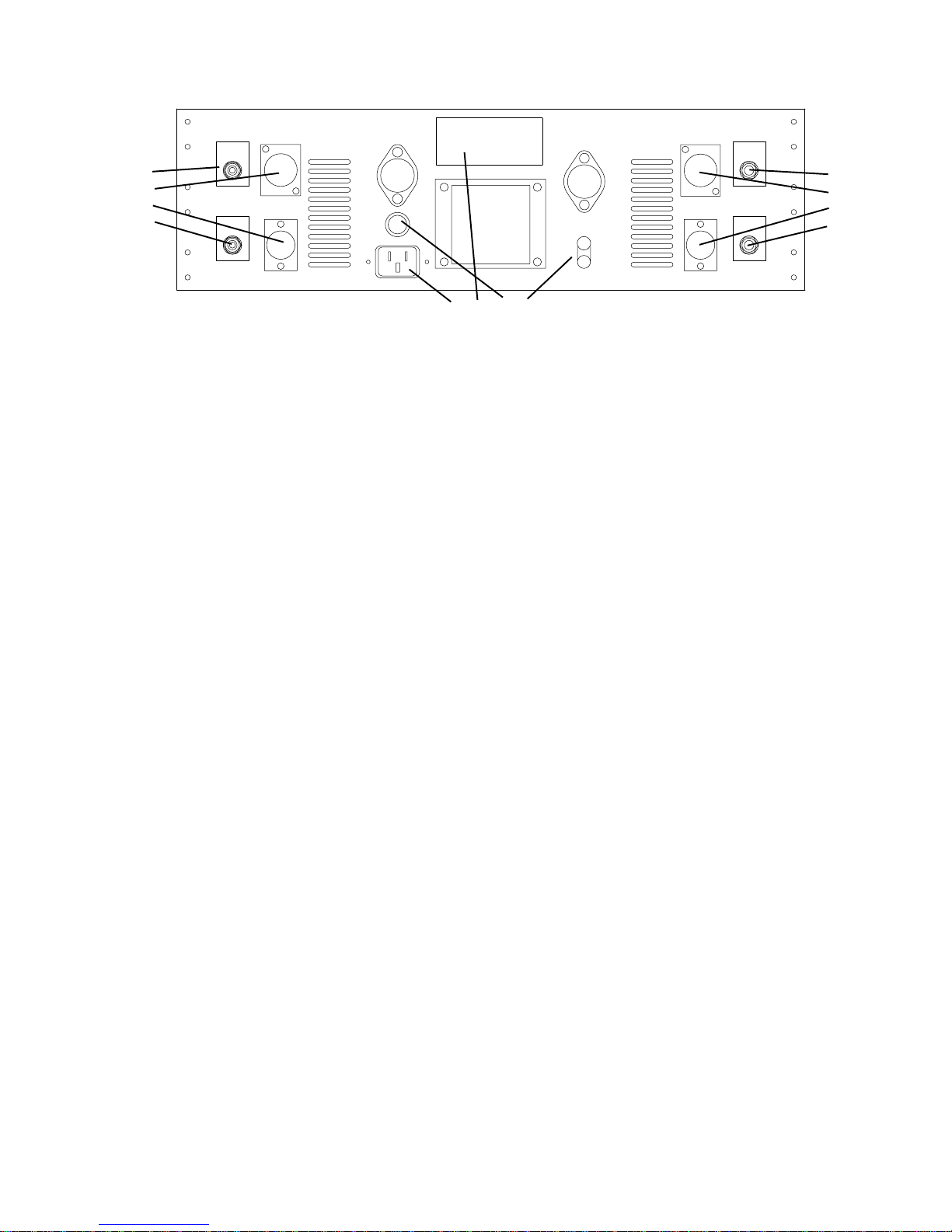
First connect all the cables, then turn on the power, wait 30 seconds, then have fun, as if we had to tell you....
1) POWER CONNECTOR. First verify the POWER SWITCH on the front panel is off (CCW). Use the power cable supplied with your
Massive Passive. One end goes here and the other end goes to the wall outlet. You know all this.
2) VOLTAGE LABEL (ON SERIAL STICKER). Just check that it indicates the same voltage as is normal in your country. It should
be. If it says 120V and your country is 220V, then call your dealer up. If it says 120V and you expect 110 it should work fine.
3) FUSE. Unplug the power cable first. The Fuse Cap needs a push then turn a quarter twist CCW to pull off. Fuses are meant to "blow"
when an electrical problem occurs and is essentially a safety device to prevent fires, shocks and big repair bills. Only replace it if it has
"blown" and only with the same value and type (2A slow-blow for 120V, 1A slow-blow for 220V). A blown fuse either looks blackened
internallyorthelittlewireinsidelooksbroken.AblownfusewillpreventalltheLEDSfromlightingandwillpreventanypowerandaudio.
4) GROUND TERMINALS. You probably don't need to worry about these. Normally there is a metal strip joining CIRCUIT and
CHASSIS Grounds. This is the first place to look if you get a hum. Make sure the strap hasn't fallen off or use a piece of wire to join the
terminals.TheCIRCUIT Ground istheinternalaudio ground (includingthe1/4" jack sleeves).TheCHASSISGround isthemetalchassis,
third pin electrical ground and pin 1 of the XLRs. Some studios use special grounding practices and these terminals are meant to make it
easy to hook up this unit for a wide variety of installations. They also help with troubleshooting hum problems.
5) PHONE JACK INPUT. (Channel One or Left) Accepts balanced or unbalanced sources. Factory set-up for +4dBu pro levels. There
are some DIP switches internally that can change this to -10dBv semi-pro or hi-fi levels. The pin out is as follows: Tip = Positive = Hot,
Ring=Negative=Loworground,Sleeve=CircuitGround.IfyouuseTRSplugsbesurethattheringisconnectedtothenegativeorground
and not "open". Input impedance is 20K ohms. See page 16 & 17 for the DIP Switch details.
6) XLR JACK INPUT. (Channel One or Left) Accepts balanced or unbalanced sources. Only for +4dBu pro levels. The DIP switches
havenoeffect on theXLRs. Thepin outisas follows: PIN2= Positive =Hot,PIN 3=Negative = Loworground, PIN1= Chassis Ground.
BesurethatthePIN3isconnectedtothenegativeorgroundandnot "open" or a 6dBlossorlossofsignalwillhappen.Ingeneral,theXLRs
and +4 pro levels are slightly preferable over phone plugs especially if gold plated matching XLRs and good cable are used.
7)XLR JACK OUTPUT. (Channel One or Left) Transformer Balanced and Floating. Only for +4dBu pro levels. The DIP switches have
no effect on the XLRs. The pin out is as follows: PIN 2 = Positive = Hot, PIN 3 = Negative = Low or ground, PIN 1 = Chassis Ground.
Be sure that the PIN 3 is connected to the negative or ground and not "open" or a complete loss of signal will happen. Output impedance
is 150 ohms and output levels can reach +37 dBv (hot) which may distort the next piece in the chain.
8) PHONE JACK OUTPUT. (Channel One or Left) Unbalanced output only. Factory set-up for +4dBu pro levels. There are some DIP
switches internally that can change this to -10dBv semi-pro or hi-fi levels (with a phase reverse). The pin out is as follows: Tip = Positive
=Hot, Sleeve = Circuit Ground. If you use TRS plugs be sure that the ring is connectedto the negativeor ground andnot "open". See page
16 & 17 for the DIP Switch details.
9) PHONE JACK INPUT. (Channel Two or Right) Same as 5 above.
10) XLR JACK INPUT. (Channel Two or Right) Same as 6 above.
11) XLR JACK OUTPUT. (Channel Two or Right) Same as 7 above.
12)PHONE JACK OUTPUT. (Channel Two or Right) Same as 8 above.
4
THE BACK PANEL

1K2
1K8
27K
12K
8K2
5K6
3K9
2K7
1K8
1K2
820
560220
330
470
680
1K 1K5 2K2
3K3
4K7
6K8
10K
FREQUENCY FREQUENCY
2K7
FREQUENCY
3K9
820
560
390
270
180
120
82
FREQUENCY
680
1K
470
330
220
150
68
47
33
22
100 100
22
33
47
68
150 220
330
470
1K
680
FREQUENCY
82
120
180
270
390 560 820
3K9
FREQUENCY
2K7
FREQUENCYFREQUENCY
10K
6K8
4K7
3K3
2K2
1K5
1K
470
330
220 560
820
1K2
1K8
2K7 3K9 5K6
8K2
12K
27K
1K8
1K2
BANDWIDTH
20
020
0
BANDWIDTH
20
0
BANDWIDTH
20
0
BANDWIDTH
20
0
BANDWIDTH
20
0
BANDWIDTH
20
0
BANDWIDTH
20
0
16K 16K
DB
BANDWIDTH
DB DB DB DB DB DB DB
680
MASSIVE PASSIVE
STEREO EQUALIZER
12K 7K5
22 39 68 120
220
18K
00
POWER
9K
OFF 6K
7K5
OFF
9K
18K 12K
OFF OFF 220
120
68
39
22
GAIN
6K
LOW
PASS
HIGH
PASS
IN IN
+4
-6 -6 +4
BOOST
CUT
SHELF
BELL
220 ±10K82 ±3K922 ±1K 560 ±27K
BELL
SHELF
CUT
OUT
BOOST BOOST
OUT
CUT
SHELF
BELL BELL
SHELF
CUT
OUT
BOOST
OUT
BELLCUT
OUT
SHELF
BOOST
560 ±27K
BELLCUT
OUT
BOOST
220 ±10K
BELLCUT
OUT
BOOST
82 ±3K9
CUT BELL
OUT
SHELF
22 - 1K
BOOST SHELFSHELF
1) The Power Switch: First things first, turn it clockwise to power up the unit. There is no "power on LED", instead you can
useanyoftheBoost/Off/CutswitchesinBoostorCutandtheylightimmediatelywithpoweron.Thereisa"warm-up"circuit
that forces the unit into "Bypass" for about 20 seconds, to prevent big thumps from hitting your speakers. This also prevents
the blue LEDs that indicate "EQ IN" from lighting up for that 20 seconds. This is not a total hardwire bypass - if power is not
on, the unit will not pass audio. At trade shows, we have seen a few people turn the "Power Switch" by accident, perhaps
thinking it was a tone control. Not knowing, there is a "warm-up" circuit, and seeing no blue light action, they thought they
may have broken the unit. The lack of a "power LED" is just one of the deliberate ideosyncracies. 4 reasons: there wasn't a
great place to put one, it was redundant with 16 boost/cut LEDs (we were laughing at other panels with dozens of lit LEDs
andafastturn-onLCDscreenalso sporting a bigpowerLED),andthisunitismeant for professionals thatweassumecanplug
in a piece of gear, see (or feel) the switch and turn it on, and it may annoy those who want all gear to be just "normal" ;-)
2)EQINbuttons:Pushtoactivatethe EQ circuits. ThebuttonsglowbluewhenEQ is INincludingtheFiltersandGain Trims.
The"warm-up"circuitprevents bothEQtobe IN andthebuttonsfrom lightingwhenitfirst gets poweredup. In"bypass"(un-
lit) the tubes are not in circuit but the input amplifier and balanced output transformer are in circuit. Yes, real blue LEDs.
3) Gain Trims: Intended to help match levels between "Bypass" and "EQ IN" modes so that the EQ effect can be more
accurately judged. It is difficult to compare if the level jumps up or down and easy to prefer EQ when mostly it is just louder.
These trims only have a small range of -6 to +4 dB of gain. With drastic EQ there may not be enough range to match levels
but with drastic EQ this kind of comparison is of little use. The range is small to allow easier and finer adjustments.
4) Low Pass Filters: They pass lows and chop highs. There is a separate filter for each switch setting and they only share the
switch and one resistor. The filters are entirely passive and "inserted" between the boost sections and cut sections.
The 18kHz filter is probably most useful for warming up digital. It seems to remove some irritating super-sonic noise
associated with digital to analog converters. It is designed as a modified eliptical filter down 60dB one octave up (36kHz) on
paperbutinreallife"only"dropsabout 40 dB. Itisflatwithin0.5dBupto16kHzthen very steeply drops.Itissonicallysubtle.
12kHz position can be considered general purpose hiss killing. It is also very flat up to 11kHz and drops at 30 dB/octave.
9kHz, 7.5kHz & 6 kHz. These are intended for more creative sound sculpting than as utility filters. They have a 1.5 to 2 dB
bump or boost right before they cut at 18dB/octave. This helps compensate for the percieved loss of highs while still allowing
deep HF cuts. This gives them a little color and edge as opposed to just dullness. You may find they help remove some of that
buzzy super high distortion of cranked guitar rigs as well as help some synth and bass sounds. They are also intended to help
with "effects" such as "telephone sound" and vintage simulations and for some techno, rap and industrial style music.
5) High Pass Filters: They pass highs and chop lows. There is a separate filter for each switch setting and they only share the
switch and one resistor. The filters are entirely passive and "inserted" between the boost sections and cut sections. They are
all 18dB/octave (most modern filters are 12), with no bumps and no resonances. We use a large, low DCR, custom inductor.
The 22Hz is very subtle and is designed to remove sub-sonic frequencies that may have been boosted by previous EQ. Most
signal below 25Hz is only good for testing or messing up sub-woofers. You may not hear the effect in the studio, but often
youcanseeitonthemeters.Nowthatsub-woofersarebecomingcommoninautosandconsumersystems,wearehearingmore
complaints of excess lows and LF garbage. This filter is in response to these concerns and requests from mastering engineers.
The 39Hzfilter can be used similarly, but may be audible with some material. This filter, as with the others, can be used with
thenormalboost/cutsectionsforamoretailoredlowEQ.ThiscanallowbiggerandmoreeffectiveLFboostswhileminimising
the side-effects of excessive woofer excursions and unwanted audible LF noise like air conditioner or subway rumble.
The 68Hz filter is also general purpose and ideal for most vocals and pop removal. Also good in combination with shelves.
120 and 220Hz filters are intended for garbage removal, sonic sculpting, and effects. 120 is useful for some vocals. The 220
is for some close miked hi-hats and percussion instruments. Yup, 220Hz tends to be drastic and only occasionally valuable.
Check out the curves on page 16 for a little more detail on these filters.
12345
5
THE FRONT PANEL

OUT
BELL
SHELF
CUT
BOOST
DB
020
BANDWIDTH
100
22
33
47
68
150 220
470
1K
680
FREQUENCY
BOOST
OUT
CUT
SHELF
BELL
560 - 27K
DB
16K
020
BANDWIDTH
FREQUENCY
560
820
1K2
1K8
2K7 3K9 5K6
8K2
12K
27K
22 - 1K
330
GAIN
CCW = FLAT
BANDWIDTH
CCW = WIDE
FREQUENCY
SELECT
BOOST
OFF
CUT
BOOST
OFF
CUT
LOW SHELF
BELL
HIGH SHELF
BELL
1
2
3
4
5
1) BOOST / OUT / CUT, TOGGLE. Each band has individual toggles to select whether that band will boost or cut or be
bypassed. "OUT" is a hardwire bypass for that band. Unlike most EQs, you must select boost or cut for each band. There are
severalgoodreasonsforthisarrangement.First,becausetheboostpartofthecircuitisinadifferentplacethanthecutpartbecause
itispassive,thisallowsustousethesamecomponentsinbothsectionsbutdoingessentiallyoppositefunctions.Theconventional
arrangement of a boost/zero/cut pot (baxandall) circuit was avoided to really make it passive. This switch also allows twice the
resolution of the "GAIN" pot and a much more accurate "zero". The center detent of conventional EQs is rarely the "electrical"
centerofthepotsowhatyouexpectiszeroisoftenalittleEQed.Thistoggleallowssomeofus,whousedipEQtoreduceoffending
frequenciestoverifythosefrequenciesin"Boost"andthenswitchto"Cut".Finally,itallowsustobypasseachbandindividually,
without losing our "GAIN" pot setting rather than resetting a band to zero or bypassing the entire EQ.
2) SHELF & BELL. The two lowest (leftmost) bands can each be a special Low Shelf or conventional Bell shape. The two
highest(rightmost) bandscan each be a specialHigh Shelfor conventionalBell shape. Shelf & Belldescribe theEQ's shape.We
included some diagrams to help visualize these curves. Bell curves focus their boost and cut at given frequency and the further
away we get from that frequency, the less boost or cut. The bell curves on the Massivo are moderately wide and the "Bandwidth
Control" does not have a lot of range and it also affects the maximum boost and cut (like a Pultec). Shelf slopes generally boost
(or cut) towards the highs or lows (thus high shelves and low shelves). These are not to be confused with "high or low filters"
which purely cut above or below a given frequency. Shelves also have gain or dB controls which allow you to just boost or cut
a little bit if desired - filters never have these controls. The Massive Passive allows each of the 4 bands to be switched to shelf.
The two mid shelves are almost the same asthe outer ones but justhaveother (interleaved) frequencychoices. For example, you
can set up the mid-high shelf to start boosting at 3K3, say 4 dB, then apply another high shelf to boost 12K, say for 10 dB, which
provides a few gentle gradual steps. BTW, the maximum boost in the example is 10 dB (not 14) and occurs around 20 kHz. You
maynoticethatasyouswitchbetweenbellandshelftheamountof"grab"mayseemtobelessinshelf.Notreally,botharecapable
of 20 db boosts but towards the extremes that boost may be sub-sonic or super-sonic because we "spec" the shelf at the 1/2 way
point(10dB),notthe3dBdown(orup)ormaximumpoint.Whenyouchoosefrequenciesclosertothemids this"effect"ismuch
less however if the "bandwidth" is medium to narrow the "effect" is more pronounced. Most EQs don't allow one to switch from
bell to shelf and don't have a functioning "bandwidth" in shelf mode and this may be understandably unfamiliar ground.
3) GAIN. This sets the boost and/or cut depth or amount and works with the BOOST, OUT, CUT, TOGGLE. FLAT is fully
counter-clockwise not straight up "12:00" like most EQs. It is more like a Pultec in this regard. Maximum boost or cut is fully
clockwiseand can beup to 20dB -but not necessarily.There is afair amountof interaction withthe BANDWIDTH control.The
maximum of 20 dB is available in Shelf modes when the Bandwidth is CCW and is about 12 dB when the Bandwidth is CW.
The maximum of 20 dB is available in Bell modes when the Bandwidth is CW and is about 6 dB when the Bandwidth is CCW.
Atstraightup"12:00"inBellmode"narrow"expectabout8dBofboostorcut. Inotherwords,youshouldn'texpectthemarkings
around the knob to indicate a particular number of dBs. Many Eqs are this way. On the other hand, this interaction is the result
of natural interactions between components and tends to "feel" and sound natural as opposed to contrived.
These4GAINcontrolshavesomeinteractionwitheachotherunlikeconventionalEQs.ItisaparallelEQratherthanthefarmore
commonseriesconnectedstyle. If yousetup all 4bandstoaround 1kHz andboosedall20 dB, thetotalboostwill be20dBrather
than 80dB (20+ db of boost and 60 dB into clipping). This also implies, that if you first boost one band, that the next three will
notseemtodoanythingiftheyareatsimilarfrequenciesandbandwidths.Virtuallyallotherparametricsarebothseriesconnected
and designed for minimal interaction, which seems to be quite appealing if you wear a white lab coat with pocket protectors ;.)
Actually,therearevalid arguements forthosegoalsand there are definatelysomeapplicationsthat require them.However,there
isalsoavalidpoint foranEQthatissubstantiallydifferentfromthe"norm",andforaudiotoysthathaveartisticmeritandpurpose
and not just scientific interest or gimmickry. We tried to balance artistic, technological and practical considerations in the
Massivo, and offer both some new and old approaches that appealed to the ears of recording engineers (and our own ears).
6
THE 4 BANDS

4) BANDWIDTH. Similar to the "Q" control found in many EQs. A more accurate term here would be "Damping" or
"Resonance" but we used "Bandwidth" to stay with Pultec terminology and because it is a "constant bandwidth" (*) design
rather than "constant Q" and because of the way it uniquely works in both Bell and Shelf modes. In Bell modes, you will
find it similar to most Q controls with a wider shape fully CCW and narrower fully CW. The widest Q (at maximum boost)
is about 1 for the 22-1K band and 1.5 for the other 3 and the narrowest Q is about 2.5 to 3 for all of the bands and most of
the frequencies. On paper, the bell widths appear to have less effect than is apparent on listening and the sound is probably
more due to "damping" or "ringing" and the way it interacts with the gain. Also some people associate a wide bell on
conventionalEQswithmoreenergyboostorcut,andatfirstimpressiontheMassivoseemstoworkbackwardcomparedwith
that and narrow bandwidths give more drastic results. On the Massive Passive a narrow bandwidth bells will allow up to the
full 20 dB of boost (or cut) and wide bandwidths significantly less at about 6 dB maximum.
InShelfModestheBandwidthhasaspecialfunction.WhenthisknobisfullyCCW,theshelfcurvesareverysimilartoalmost
allother EQs.As you increase the Bandwidth control, you begin tointroduce abell curvein the opposite direction. So if you
havea shelfboost, you gradually add a bell dip which modifiesthe overallshelf shape.At straight up, it stays flatter towards
the mid range, and begins to boost further from the mids with a steeper slope but the final maximum part of the boost curve
stays relatively untouched. With the Bandwidth control fully CW, that bell dip becomes obvious and is typically 6dB down
at the frequency indicated. The boost slope is steeper and the maximum boost may be about 12 dB. These curves were
modelled from Pultec EQP1-As and largely responsible for the outrageous "phatness" they are known for. As you turn the
Bandwidth knob (CW), it seems as if the shelf curve is moving further towards the extreme frequencies, but mostly of this
is just the beginning part of the slope changing and not the peak. This also implies, that you may find yourself using
frequencies closer to the mids than you might be used to. These shelf curves have never been available for an analog high
shelf before and provide some fresh options.
5) FREQUENCY. Each band provides a wide range of overlapping and interleaving frequency choices. Each switch
positionis selecting adifferent capacitor and inductor. Only the 22 and 33 Hz on thelow band andthe 16K and 27K in shelf
mode deserve some special explanation. These have been "voiced" a little different from the rest and are somewhat unique.
Why "modify" the way the 22, 33, 16K and 27K shelves work? When we specify that a low shelf is at 22 Hz, it means that
only the half-way point of the boost (or cut) is 22 Hz. If we dial up a 20 dB boost set at 22Hz then 22 Hz is half-way up
theslopeorboosted10dB.Thefullamountoftheboost(20dB)isonlykickinginaround 2 Hz. This is dangerous and almost
useless for anything except whale music. Not only that, but now we have a Bandwidth control that seems to push the
frequencylower,and at12:00essentiallyflattenstheEQat22Hz.SowechangedtheBandwidthcontrolforthosetwolowest
frequencies so that it acts as a HP filter as you turn it CW and tends to prevent boosting excessive sub-sonic frequencies. To
our ears, it seems to "tighten up" the shelf and removes some of the sloppy looseness associated with those sub-sonics.
The 16kHz and 27kHz shelfs were also specially "voiced" for similar reasons. In this case, a 50kHz low pass filter prevents
theseshelfs from helping recieve the local AM radiostations. The Bandwidth-Dip frequencies were lowered to about8 kHz
so that on a single band, you would have more effective control between the balance of "air" and "sibilance". In practice, it
gives you a great deal of air without the usual problem "esses" when you boost a lot of highs.
At extreme high and low frequencies (including 10K and 12K), you might get some unexpected results because of the
Bandwidth/Shelffunction.Forexample,youcanset up 20 dBofboostat12Kanditcansoundlikeyoujustlosthighsinstead
of boosting. This happens when the Bandwidth control is more CW only and not when it is CCW. Why? You are creating
a dip at 12K and the shelf is only beginning at the fringes of audibility but the dip is where most of us can easily percieve.
It takes a little getting used too the way the controls interact. The reverse is also true, where you set up a shelf cut and you
get a boost because of the Bandwidth control being far CW. In some ways this simulates the shape of a resonant synthesizer
filter or VCF except it doesn't move. These wierd highs are useful for raunchy guitars and are designed to work well with
the Filters. There are a lot of creative uses for these bizarre settings including messing up the minds of back-seat engineers.
There is some example settings near the back page that may help to show how different this EQ is.
_________________________________________________________________________________________________
* For the technically minded, there is another and stronger definition of "constant bandwidth" filters but it doesn't seem to
apply to pro audio. In FM radio recievers "constant bandwidth" is a type of filter used in the tuning sections, and the filter
width allows the reception specs to stay constant as the tuning filter is moved. It is unlikely anybody has ever offered this
type of constant bandwidth filter lowered to audio frequencies. Given that we have about 3 decades of frequency in audio,
can you imagine an EQ that had a Q of 0.3 (very wide) in the lows and a Q of 30 in the highs (extremely narrow)? For
perspective, a Q range of 1 to 10 is a pretty wide span. There are a few EQs that get slightly narrower Qs as the frequency
isincreasedbutnotevenclosetotrue"constantbandwidth"theRFengineersappreciate.Thisiseitherdeliberateortheresult
oftryingtosqueezetoomuchrangeoutofasimpleinductor.ManleyLabsprefersthebellshapetoremainrelativelyconstant
atallfrequenciesandtheMassivouses14tapinductorswithlowDCRtoprovidethis.Theonlypossiblyuseful"Q variation"
(other than a Q knob) is a circuit that gives a wider Q for boosts and a narrower Q for cuts. This very rare technique is cool
for music. It corresponds to the way many engineers use EQs and reduces audible ringing and EQ "signature".
7

NOTES
1) Do not assume the knob settings "mean" what you expect they should mean. Part of this is due to the interaction of the controls. Part
is due to the new shelf slopes and part due to a lack of standards regarding shelf specification.
2)Youmayfindyourselfleaningtowardsshelffrequenciesclosertothemidsthanyouareusedtoandthe"action"seemsclosertotheedges
of the spectrum than your other EQs. Same reasons as above.
3) You may also find yourself getting away with what seems like massive amounts of boost. Where the knobs end up, may seem scarey
particularly for mastering. Keep in mind that, even at maximum boost, a wide bell might only max out at 6 dB of boost (less for the lowest
band) and only reaches 20 dB at the narrowest bandwidth. On the other hand, because of how transparent this EQ is, you might actually
be EQing more than you could with a different unit. Taste rules, test benches don't make hit records, believe your ears.
4)Sometimestheshelfswillsoundprettywierd,especially(only)atthenarrowbandwidthsettings.Theymightseemtobehavingacomplex
effect and not only at the "dialed in" frequency. This is certainly possible. Try wider bandwidths at first.
5)If youseem to be boosting all4 bandsat widelyseparated frequencies and not hearingmuch "EQ"as youmight expect(except for level)
thisis a side-effectof a passiveEQ and probably a good thing. To get drastic sounding EQ you should tryboosting a fewbands and cutting
a few bands. In fact, it is usually best to start with cutting rather than boosting.
6)AreasonablestartingpointfortheBandwidthforshelvesisstraightuporbetween11:00and1:00.Itwasdesignedthiswayandisroughly
where the maximum flatness around the "knee" is, combined with a well defined steep slope.
7)TheMassive Passivehassome internal dipswitches for betteroptimised-10 applicationshoweverit is aslightly flawed implementation
-itreversesthephaseorpolaritysoweonlyrecommend using the +4factorysetting.Ifonemustuse -10unbalancedmode,pleaseconsider
using special cables where the input is wired ring hot or using the phase switch on the console or workstation. On the other hand, if a set-
up requires -10 levels and can't deal with +4 pro balanced signals, then maybe, absolute polarity issues are a relatively minor problem.
8) The Massive Passive may sound remarkably different from other high end EQs and completely different from the console EQs. Yes,
this is quite deliberate. Hopefully it sounds better, sweeter, more musical and it complements your console EQs. We saw little need for yet
another variation of the standard parametric with only subtle sonic differences. We suggest using the Massive Passive before tape, for the
bulk of the EQ tasks and then using the console EQs for some fine tweaking and where narrow Q touch-ups like notches are needed. The
Massive Passive is equally at home doing big, powerful EQ tasks such as is sometimes required for tracking drums, bass and guitars, or
for doing those demanding jobs where subtlety is required like vocals and mastering.
CREDITS
PRODUCED BY EVEANNA MANLEY
EveAnna suggested that we work on a "tube parametric", and had a lot to do with the look of the Massive Passive including the
back-lit panels, engraved inserts and the name. She cleverly allowed the designer almost total freedom in the execution.
NAMED BY: RANDY PORTER & JUSTIN WEIS
We were less than thrilled by the working names we were using which included "Furthermore", and "Antiqualizer" so we ran a
"name this EQ" contest on our website with a cash or credit prize (good reason to check out www.manleylabs.com once in a
while). We got hundreds of names (most featuring the letter Q) but Randy and Justin separately came up with Massive Passive
and they both won and they both applied their credit towards the EQ they named. The nickname "Massivo" comes from
"Massivo Passivo" which the Manley assemblers prefer to call it.
DESIGNED BY "HUTCH"
Craig Hutchison came up with the concepts, circuits, and boards. Given that the Massivo is quirky, eccentric and over-the-top,
you can pretty much guess what the designer is like. He used SPICE3, WAVES plug-ins and several complex looking
breadboards and many listening tests in the process. Again, blame him for this long-winded, opinion-filled manual.
OTHER VALUED CONTRIBUTORS
Baltazar helped with circuit boards, mechanical drafting and proto-assembly. Michael Hunter helped develop all the inductors
(which was a major task). Dave Hecht (Record Plant), George Peterson (MIX), Seva (WAVES) and Ross Hogarth (Freelance
Engineer) were valuable sounding boards in the concept stage and Dave was the first to really evaluate it. Elias Guzman
fabricated all the circuit boards including several protos. Pre-production beta-testers include Larry, Rick, Don & Spencer at
Precision Mastering, Dave Collins at A&M Mastering, and Eddie Schreyer at Oasis Mastering, all known for their ears and
honest opinions. Last but not least, our dealers for their faith in us, especially, Barb and Al at Studio Tech in Texas, Raper
Wayman in the UK, Coast in Hollywood, and many more. 8

Beginnings
The very earliest equalizers were very simple and primitive by
todays standards. Yes, simpler than the hi-fi "bass" and "treble"
controls we grew up with. The first tone controls were like the tone
controls on an electric guitar. They used only capacitors and
potentiometers and were extremely simple. Passive simply means
no "active" (powered) parts and active parts include transistors,
FETs, tubes and ICs where gain is implied. "Passive" also implies
noboostis possible-only cut.Themost recent"purelypassive EQ"
we know of was the EQ-500 designed by Art Davis and built by a
numberofcompaniesincludingUnitedRecordingandAltecLansing.
Ithada10dBinsertionloss.Notubes. It had boostandcutpositions
but boost just meant less loss. Manley Labs re-created this vintage
piece and added a tube gain make-up amp for that 10 dB or make-
up gain to restore unity levels. It has a certain sweetness too.
Youhaveprobablyheardofpassivecrossoversandactivecrossovers
in respect to speakers or speaker systems. Each has advantages.
Almost all hi-fi speakers use a passive crossover mounted in the
speaker cabinet. Only one amp is required per speaker. Again,
passive refers to the crossover using only capacitors, inductors and
resistors. Active here refers to multiple power amplifiers.
Oneofthemaindesigngoals of the MassivePassivewastouseonly
capacitors, inductors and resistors to change the tone. Pultecs do it
this way too and many of our favorite vintage EQs also relied on
inductors and caps. In fact, since op-amps became less expensive
than inductors, virtually every EQ that came out since the mid '70's
substituted ICs for inductors. One is a coil of copper wire around a
magneticcoreandtheotherisprobably20ormoretransistors.Does
the phrase "throwing out the baby with the bath water" ring a bell?
Another design goal was to avoid having the EQ in a negative
feedbackloop.Baxandallinventedthecommoncircuitthatdidthis.
It simplified potentiometer requirements, minimised the number of
parts and was essentially convenient. Any EQ where "flat" is in the
middleof thepot's range and turning thepot oneway boostsand the
otherwaycutsisavariationoftheoldBaxandallEQ.Pultecsarenot
this way. Flat is fully counter-clockwise. For the Massive Passive,
Baxandall was not an option. The classical definition of "passive"
has little to do with "feedback circuits" and we are stretching the
definition a bit here, however, it certainly is more passive this way.
Weonlyuse amplificationtoboostthesignal.FlatGain!Whatgoes
iniswhatcomesout.Ifwedidn'tuseanyamplifiers,youwouldneed
toreturn the signal to amic pre because the EQcircuit eats about 50
dB of gain. Luckily, you don't have to think about this.
We visited a few top studios and asked "what do you want from a
newEQ?"Theyunanamously asked for"clickswitchfrequencies",
"character" rather than "clinical" and not another boring, modern
sterile EQ. They had conventional EQs all over the console and
wanted something different. They had a few choice gutsy EQs with
"click frequencies" that were also inductor/capacitor based (which
is why the frequencies were on a rotary switch). Requests like
"powerful", "flexible", "unusual" and "dramatic" kept coming up.
We started with these goals: modern parametric-like operation,
passive tone techniques through-out, and features different from
anything currently available and, most importantly, it had to sound
spectacular.
"The Super-Pultec"
Manley Labs has been building a few versions of the Pultec-style
EQs for many years as well as an updated version of the EQ-500
(anothervintageEQ).Theseareclassic passive EQscombinedwith
Manley's own gain make-up amplifiers. Engineers loved them but
we often heard requests for a Manley Parametric EQ with all the
modern features but done with tubes. Another request we had was
fora"Super-Pultec".Webrieflyconsideredcombiningthe"bestof"
Pultecsinto a newproduct but theidea of somebands onlyboosting
andsomeonlycuttingcouldonlybejustifiedinanauthenticvintage
re-creation and not a new EQ.
ThenextchallengewastomakeanEQthatsoundedasgoodorbetter
than a Pultec. With all the hundreds of EQs designed since the
Pultec, none really beat them for sheer fatness. We knew why. Two
reasons. EQP1-A's have separate knobs for boost and cut. People
tend to use both at the same time. You might think that this would
just cancel out - wrong.... You get what is known as the "Pultec
Curve" . The deep lows are boosted, the slope towards "flat"
becomes steeper, and a few dB of dip occurs in the low mids. The
second reason for the fatness and warmth was the use of inductors
and transformers that saturate nicely combined with vacuum tubes
for preserving the headroom and signal integrity.
Couldweusea"bandwidthcontrol"tosimulatethe"PultecCurve(s)?
The Pultec curve is officially a shelf and shelf EQs don't have a
"bandwidthorQknob"-onlythebellcurves.So,ifwebuiltapassive
parametric where each band could switch to shelf or bell and used
that"bandwidth"knobintheshelfmodeswecouldnotonlysimulate
the Pultecs but add another parameter to the "Parametric EQ" We
found that we could apply the "Pultec Curve" to the highs with
equally impressive results. This is very new.
TheMassivePassivediffersfromPultecsinseveralimportantareas.
Rather than copy any particular part of a Pultec, we designed the
"Massivo"fromthegroundup.Asmentioned,each band being able
to boost or cut and switch from shelf to bell is quite different from
Pultecs. This required a different topology than Pultecs which like
most EQs utilize a "series" connection from band to band. The
Massive Passive uses a "parallel" connection scheme.
Aseriesconnectionwouldimplythatforeachband's20dBofboost,
there is actually 20 dB (more in reality) of loss in the flat settings.
Yeah, that adds up to over 80 dB, right there, and then there is
significantlossesinvolvedifoneintendstousethesamecomponents
tocutandtoboost.Andmorelossesinthefilterand"gaintrim".That
much loss would mean, that much gain, and to avoid noise there
would need to be gain stages between each band and if done with
tubes would end up being truly massive, hot and power hungry.
Instead, we used a parallel topology. Not only are the losses much
more reasonable (50 dB total!) but we believe it sounds more
"natural"and"musical".InmanywaystheMassivePassiveisavery
unusual EQ, from how it is built, to how it is to operate and most
importantly how it sounds.
We designed these circuits using precise digital EQ simulations,
SPICE3 for electronic simulations, and beta tested prototypes in
major studios and mastering rooms for opinions from some of the
best "ears" in the business.
9
Another important concept. When you use the shelf curves the
frequencies on the panel may or may nor correspond to other EQ's
frequencymarkings.Itseemsthereareacceptedstandardsforfilters
and bell curves for specifying frequency, but not shelves. We use a
commonform of specwhere the "freq" corresponds tothe half-way
dB point. So, if you have a shelf boost of 20 db set at 100 Hz, then
at100,itisboosting10dB.Thefull20dBofboostishappeninguntil
below 30 Hz. Not only that, like every other shelf EQ there will be
a few dB of boost as high as 500 Hz or 1K. This is all normal,
except.........
Except we now have a working "bandwidth control" in shelf mode.
With the bandwidth set fully counter-clockwise, these shelves
approximate virtually ever other EQ's shelf (given that some use a
different freq spec). As you turn the bandwidth control clockwise,
everythingchangesanditbreaksalltherules(andsoundsawesome).
Lets use an example. If graphs are more your style, refer to these as
well.Supposeweuse4.7Konthethirdbandbyswitchingto"boost"
and "shelf" and turning the "bandwidth control" fully counter-
clockwise. Careful with levels from here on out. Just for fun, select
4.7kHz and turn the "dB" control to the max - fully clockwise. This
should be like most other shelf EQs, except with better fidelity, (if
youcansetthemtoaround5kHz!).Now,slowlyturnthe"bandwidth"
clockwise. Near 12:00 it should be getting "special". It also sounds
higher (in freq). Keep turning. At fully clockwise it seems to have
gotten a little higher and some of the sibilance is actually less than
in "bypass". It sort of sounds as if the bandwidth is acting like a
variable frequency control but better. More air - less harshness.
Compared to "conventional parametrics" in all their variations, the
Massive Passive has just "upped the ante" by adding a few useful
new parameters. The first is the use of the "bandwidth" in shelf
modes.Secondistheabilitytoswitcheachandeverybandintoshelf.
The original parametrics were only "bell". We have seen some EQs
that allow the lowest and highest bands to switch to shelf. Now you
can use two HF shelfs to fine tune in new ways without chaining
several boxes together. Lastly, each band can be bypassed or
switchedfromboosttocutwithoutlosingaknobsetting.Thisallows
twice the resolution from the "dB" pots and allows one to exagerate
an offending note in order to nail the frequency easier, then simply
switchto"cut".Youcanalwayscheck,withoutlosingthedBsetting
by switching back to "boost" for a minute. You can also have
absolute confidence that the "zero" position on the dB pot is "flat"
which is not the case with center detented pots. Mechanical center
and electrical center are rarely the same.
"The Passive Parametric"
For years, we had been getting requests for a Manley parametric
equalizer,butitlookeddauntingbecauseeveryparametricweknew
of used many op-amps and a "conventional parametric" would be
very impractical to do with tubes. Not impossible, but it might take
upwards of a dozen tubes per channel. A hybrid design using chips
for cheapness and tubes for THD was almost opposite of how
Manley Labs approaches professional audio gear and tube designs.
Could we combine the best aspects of Pultecs, old console EQs and
high end dedicated parametric EQs?
What is the definition of a "Parametric Equalizer"? We asked the
man who invented the first Parametric Equalizer and coined the
term. He shrugged his shoulders and indicated there really is no
definition and it has become just a common description for all sorts
of EQs. He presented a paper to the AES in 1971 when he was 19.
Hisname is George Massenburg and still manufacturessome of the
best parametric EQs (GML) and still uses them daily for all of his
major recordings. Maybe he originally meant "an EQ where one
couldadjustthelevel,frequencyandQindependently".Heprobably
also meant continuously variable controls (as was the fashion) but
this was the first aspect to be "modified" when mastering engineers
neededreset-abilityandrotaryswitches.Thenextdevelopmentwas
the variation of "Constant Bandwidth" as opposed to "Constant Q"
in the original circuits. "Constant Q" implies the Q or bell shape
staysthesameateverysettingofboostandcut."ConstantBandwidth"
implies the Q gets wider near flat and narrower as you boost or cut
more.Pultecs andpassive EQswere ofthe constant bandwidth type
and most console EQs and digital EQs today are the constant
bandwidthtypebecausemostofusprefer"musical"over"surgical".
Lately we have seen the word "parametric" used for EQs without
even a Q control.
We can call the Massive Passive a "passive parametric" but .... it
differs from George's concepts in a significant way. And this is
important to understand, to best use the Massive Passive. The dB
andbandwidthknobsarenotindependent.Wealreadynotedthatthe
QofthebellcurvewidenswhenthedBcontrolisclosertoflat.More
significantly, the boost or cut depth varies with the bandwidth
control.Atthenarrowestbandwidths(clockwise) you candialin20
dB of boost or cut. At the widest bandwidths you can only boost or
cut6dB(andonly2dBinthetwo22-1Kbands).Somehow,thisstill
sounds musical and natural. The reason seems to be, simply using
basic parts in a natural way without forcing them to behave in some
idealized conceptual framework.
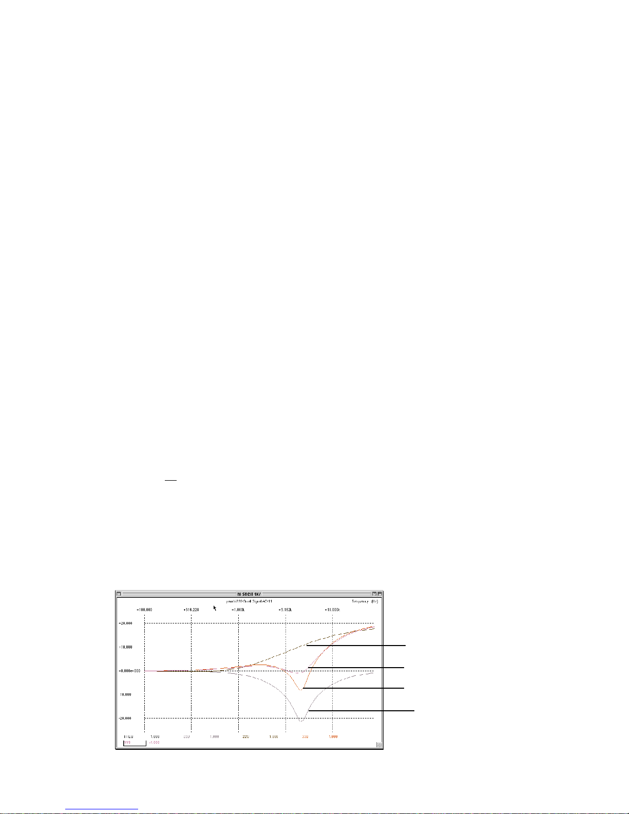
"Normal Shelf" Wide Bandwidth
"Special Shelf" Medium Bandwidth
"Pultec Shelf" Narrow Bandwidth
Bell Cut Narrow Bandwidth
"SPICE" printout
10

And Why Parallel?
The Massive Passive is a "parallel design" as opposed to the
far more common "series design". A few pages back, we
mentioned the main reason for going with a parallel design
was to avoid extreme signal loss, which would require
extreme gains and present the problem of noise or extreme
cost. The parallel approach not only avoided this but has a
number of advantages as well.
WiththeseriesEQdesign,ifyouset3bandstoboostthesame
frequency 15 dB each, the total boost will be band one plus
two plus three - or 45 dB - but then it would probably be
distortinginaratheruglyway.WiththeMassivePassive,you
candial in4bandsto boost20dbnear 1Kandit still willonly
boost 20 dB total. If you tend to boost 4 bands at widely
separated frequencies (like what happens on two day mixes
withsneakyproducers),ittendssoundalmostflat,butlouder.
OtherEQsseemtosoundworseandworseasyouboostmore
andmore.Forsomepeopleitwillactasa"safetyfeature"and
prevent them from goofy EQ. Occasionally, you may be
surprised with what looks like radical settings and how close
to flat it sounds. A side effect is that if you are already
boosting a lot of highs in one band, if you attempt to use
another band to tweak it, the second band will seem rather
ineffective.You mayhavetobackoffonthatfirstbandtoget
the desired tone. You actually have to work at making the
Massive Passive sound like heavy-handed EQ by using a
balancedcombinationofboostsandcuts.Inasenseitpushes
you towards how the killer engineers always suggest to use
EQs (ie gentle, not much, more cut than boost). This is good.
While there may be interesting arguments against any
interactionbetweenEQbands,thereasonstendtobemorefor
purelytechnicalbiasesthanbasedonlistening. Innature and
acousticsandinstrumentdesign,verylittleofthe factors that
affect tone are isolated from each other. Consider how a
guitar's string vibrates the bridge which vibrates the sound
board, resonates in the body, and in turn vibrates the bridge
and returns to the string. What is isolated? The fact that the
bandsareNOTisolatedfromeachotherintheMassivoisone
of the reasons it does tend to sound more natural and less
electronic. We noticed this effect in a few passive graphic
EQs, notably the "560" and a cut-only 1/3 octave EQ.
There is a type of interaction we did avoid. That is inductor
to inductor coupling. It is caused by the magnetic field
created by one inductor to be picked up by another. It can
cause the inductors to become an unexpected value, or if it is
band to band, can cause effects that can best be described as
goofy.IntheFilterSectionweutilizedcloseinductorspacing
togetsomehum-buckingactionbutavoidmagneticcoupling
with careful positioning. Some kinds of interaction suck and
some are beneficial.
Why Passive?
If you hate tech talk, just skip this section - it has to do with
electronic parts and circuits and design philosophy.
AllEQsusecapacitors.Theyareveryeasytouse,predictible,
cheap and simple. Some sound slightly better than others.
Inductors do almost the mirror function of capacitors.
Unfortunately, they can be difficult to use (they can pick up
hum),theycanbedifficulttopredict(theessentialinductance
value usually depends on the power going through them
which varies with audio), they are expensive and generally
haveto be custommadeforEQs.These are qualitiesthatlab-
coat engineers tend to scowl at. Some effort was aimed at
replacing the poor inductors and more effort made to bad-
mouth them and justify these new circuits. The main reason
wascost. Allofthe "classic"Eqs usedrealinductors andthat
has become the dividing line "sought after vintage" and just
old.
What the lab-coats didn't consider was that inductors may
have had real but subtle advantages. Is it only obvious to
"purists"that a coilofcopperwire maysoundbetterthan 2 or
3 op-amps, each with over twenty transistors, hundreds of
dBs of negative feedback along with "hiss", cross-over
distortion and hard harsh clipping?
Wementioned the inductance value canchangewith applied
power. This also turns out to be a surprising advantage. For
example, in the low shelf, with heavy boosts and loud low
frequency signals, at some point, the inductor begins to
saturate and loses inductance. Sort of a cross between an EQ
and a low freq limiter. The trick is to design the inductor to
saturate at the right point and in the right way.
In the mid-bands and bell curves a somewhat different effect
happens. The center-frequency shifts slightly depending on
both the waveform and signal envelope. This "sound" is the
easilyrecognizeable signature of vintageEQs.Itis not atype
of harmonic distortion (though it can be mistaken for this on
a test-bench) but more of a slight modulation effect.
Inductors in the form of transformers are also a large part of
whyvintagegearisoftendescribedas"warm"whetheritwas
built with tubes or transistors. In fact, the quality of the
transformer has always been directly related to whether a
pieceofaudiogearhasbecomesoughtafter.Saturationinthis
case involves adding odd harmonics to very low frequencies
which either tends to make lows audible in small speakers or
makesthebasssoundlouderandricher(whilestillmeasuring
"flat"). The key is how much. A little seems to be sometimes
desireable (not always) and a little more is beginning to be
muddy and a little more can best be described as "blat". The
numberofaudiotransformerexpertshasfallentoamerehand
full and some of them are getting very old.
11

Why Tube Gain Stages?
Thestupid answer isthe nameon the unitis "ManleyLabs"and that
is what we do. Unlike a current trend, we do not use tubes for THD,
clipping character, cool marketing buzz-words, or plagiarism. We
began building tube gear because we preferred the sound when it
was un-fashionable and re-introduced these glowing gain bottles to
both the hi-fi and studio communities when there was virtually no
fresh tube designs available. We also stress that, its not just the
tubes, but the way they are used. The sound of a piece of gear is due
to many design details and many of the components - always has.
In the Massive Passive, the tube gain stages are new designs
developed for this unit. We try to use minimalist techniques where
ever possible and use the appropriate technology for the purpose.
Simple vacuum tube circuits can excel for medium gain voltage
amplifiers and high headroom output stages. A simple tube stage
offers better linearity than an equally simple transistor circuit.
Transistors have a logarithmic transfer curve and are essentially
current devices. Transistor circuits are typically built with huge
excess gain which is used for more feedback in order to tame the
linearity (THD) but this feedback seems to cause audible transient
problemsandisdirectlyresponsiblefortheharshclippingcharacter.
Op-amps, which can be less noisy and lower THD, are complex
circuits which force music through many transistors and may also
bring crossover distortion artifacts and headroom issues into play.
The only alternative would have been for the Massivo to use FET /
MOSFET highvoltagediscretecircuits.Someday,wemayintroduce
aversionlikethisbutdon'tphoneusupeverymonthaskingifweare
working on it. We'll let you know.
We use an exceptional op-amp/discrete circuit for the input buffer
in order to drive the 150 ohm (worst case) EQ circuit. Not an
appropriateplacefortubes.Thefirstdesignusedatransformer(3:1)
for impedance conversion but it had a 10 dB voltage drop and thus
10 dB more noise. The new input circuit isolates input loading and
allows the tube circuits to be better optimised. We use two similar
all-tubegainstagesperchannelfor interstageandoutputlinedrivers
which together cancels some distortion. The output is capable of
driving up to +37 dBu! This stage also uses a separate winding on
the output transformer (also custom designed) for a little negative
feedbacktoallowloweroutputimpedancesandminimaltransformer
coloration. In other words, because we expect some engineers
wanting to boost 20 dB at 100 Hz occasionally, the circuits had to
becapableofcleanlydeliveringit(regardlessifthe next piece inthe
chain can deal with it). We used tubes for more headroom (300 volt
powersupply)ratherthanmoreclipping.Generallytoo,tubecircuits
clip a little smoother than mega-negative feedback IC circuits.
Some may question "tube reliability" but most major studios have
many30or40yearoldtubecompressorsandEQsrunningeveryday
and some with the original tubes. Not many 15 or 20 year old
transistor units are still working or wanted. Tubes will eventually
burnout (so do transistors),however, usually youcan easilygetthe
type of tube used 30 years ago and you won't need a soldering iron,
schematicortechnician.Yourparentsprobablyusedto"fix"theold
TV. The bottom line is, good gear tends to be more reliable, and if
a problem develops, is both easy to fix, and carries great factory
support.Weunderstandthatitsometimesinvolvesyourprofessional
livelihood and this is indeed often serious and you depend on it. If
this is the case, consider getting a few spare tubes which covers
90%+ ofemergencieswithimmediatefixes.Ourservicedepartment
hasa greatreputation withphone supportand fast turn-arounds too.
Phase Shift?
Deadlytopic.Thisisprobablythemostmisunderstoodtermfloating
aboutinthemixingcommunity.Lotsofpeopleblameornamephase
shiftforjustabout any audio problemthatdoesn'tsound like typical
distortion.Weask that youtry to approachthissubject withanopen
mindandforgetwhatyoumayhaveheardaboutphasefornow.This
is not to be confused with "time alignment" as used in speakers, or
the "phase" buttons on the console and multi-mic problems.
First-allanalogEQshavephaseshiftandthattheamountisdirectly
relatedtothe "shape"ofthe EQcurve.Most digitalEQstoo. Infact,
one could have 3 analog EQs, 3 digital EQs, and an "acoustic
equivilant", and a passive EQ, each with the same EQ shape, and
ALL will have the same phase shift characteristics. This is a law, a
fact and not really a problem. The two exceptions are: digital EQs
with additional algorithms designed to "restore" the phase, and a
rarefamilyofdigitalEQscalledFIRfiltersbasedonFFTtechniques.
Second-OpinionsaboundthatanEQ'sphaseshiftshouldfallwithin
certain simple parameters particularly by engineers who have
designedunpopularEQs.TheMassive Passive hasmorephaseshift
thanmost in thefilters andshelfs andleans towards lessin thebells.
Does this correspond to an inferior EQ? Judge for yourself.
Third - Many people use the word "phase shift" to describe a nasty
qualitythatsomeold EQs have andalsoblameinductorsfor this. Its
not phase shift. Some inductor based EQs use inductors that are too
small, tend to saturate way too easily, and create an unpleasant
distortion.TheMassivo(ofcourse)usesmassiveinductors(compared
tothetypicaltype)whichwerechosenthroughlisteningtests.Infact
we use several different sizes in different parts of the circuit based
on experiments as to which size combined the right electrical
characteristics and "sounded best". The other very audible quality
people confuse with phase shift is "ringing". Ringing is just a few
stepsunderoscillating and ismostly related tonarrowQs. It ismore
accurately described as a time based problem than phase shift and
isfareasiertohear than phaseshift.Forourpurposes,in this circuit,
theseinductorshavenomorephaseshiftorringingthanacapacitor.
Fourth- Agiven EQ"shape" should have a given phase shift,group
delay and impulse response. There also exist easy circuits that
produce phase shift without a significant change in frequency
response. These are generally called "all-pass networks" and are
usually difficult to hear by themselves. You may have experienced
a worse case scenario if you have ever listened to a "phase-shifter"
with the "blend" set to 100% (so that none of the source was mixed
in) and the modulation to zero. Sounded un-effected, didn't it, and
that may have been over 1000 degrees of phase shift. Group delay
andimpulseresponsedescribethesignalintimeratherthanfrequency
andare just differentways of describingphase shift. Someresearch
shows these effects are audible and some not. The Massive Passive
tends to show that group delay in the mids is more audible than
towards the edges of the spectrum and there may be interesting
exceptions to generalities and conventional wisdoms. The audible
differencesbetweenEQsseemstohavemoretodowithQ,distortions,
headroom and topology than with phase shift.
Fifth- Phase Shiftis not asimportant asfunctionality.For example,
we chose very steep slopes for some of the filters because we
strongly believe the "job" of a filter is to remove garbage while
minimally affecting the desired signal. A gentler slope would have
brought less phase shift but would not have removed as much crap.
12

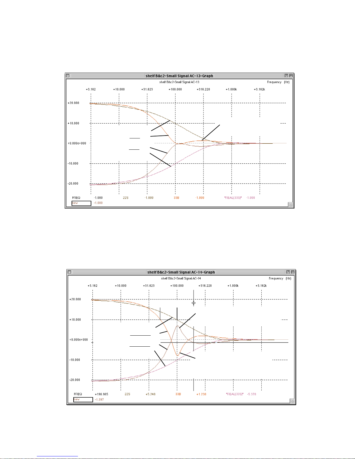
Normal Shelf Wide Bandwidth
(slope =about 4 to 5 dB/oct)
Special Shelf Medium Bandwidth
(slope = about 8 to 10 dB/oct)
"Pultec Shelf" Narrow Bandwidth
Bell Cut Narrow Bandwidth
(just for reference)
22 Hz Shelf Wide Bandwidth
22 Hz Shelf Narrow Bandwidth
33 Hz Shelf Wide Bandwidth
33 Hz Shelf Medium Bandwidth
22Hz and 33Hz are different shelves when the Bandwidth is Narrow
The top graph is for the other 20 Low shelves
LOW SHELF CURVES
Just like most EQs, a 100Hz low shelf
doesn't reach "max" until about 10 Hz.
13
LOW SHELF +20 WIDE BW
LOW SHELF +20 MED BW
LOW SHELF -20 MED BW
LOW SHELF -20 WIDE BW
LOW SHELF +20 WIDE BW
LOW SHELF +20 NARROW BW
LOW SHELF -20 NARROW BW
LOW SHELF -20 WIDE BW
NOTICE THIS 8 dB BOOST AT 100 Hz
WHILE SHELF CUTTING 100 Hz
AND NOTICE THIS 8 dB DIP
WHILE SHELF BOOSTING
THE HALF WAY (10 dB) POINT
HAS SHIFTED TO 50 Hz
THESE CURVES SHOW ONE OF THE IDEOSYNCRACIES
AND IT IS POSSIBLE FOR A LF BOOST TO SOUND AS IF IT HAS LESS LOWS
DEPENDING ON THE FREQUENCY AND INSTRUMENT.
SIMILAR CURVES APPLY TO THE HIGH SHELVES AND
PARTICULARLY 10K AND 12K CAN BE STRANGE WHEN THE BW IS NARROW
THIS IS ABOUT +1.5 DB
AT 300 Hz AND NEGLIGIBLE
MORE 100Hz SHELVES SHOWING
BOOST AND CUT WITH VARIOUS BANDWIDTHS
14
50 100
SPICE SIMULATION CURVES

Narrow Bandwidth
Bandwidth at 12:00
Wide Bandwidth
Wide Bandwidth
Bandwidth at 12:00
Narrow Bandwidth
"dB" set at max (20 dB) and changing the Bandwidth
Max Boost Narrow Bandwidth
12:00 Boost Narrow Bandwidth
Max Boost Wide Bandwidth
12:00 Boost Wide Bandwidth
Changing "dB" and Changing Bandwidth
TYPICAL BELL CURVES
15
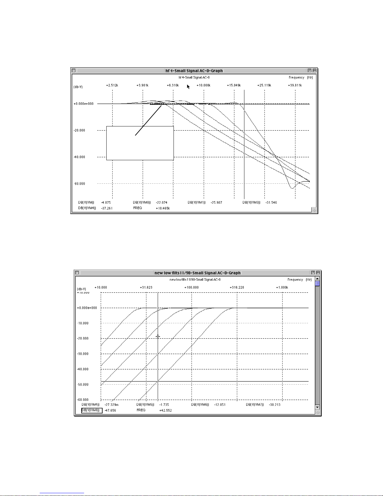
LOW PASS FILTERS
HIGH PASS FILTERS
1.5 dB bump on the 6K,
7.5K and 9K Filters
16

1) To Open: Disconnect the AC Power cable, let sit 15 minutes to allow the power supply capacitors to discharge. Remember
therearehighvoltages(300VDC)usedintheMassivePassiveandthatthecapacitorsmaycontinuetoholdachargeafterpower
is removed - BE CAREFUL! We suggest using gloves and/or "one hand only" when the top is off.
RemovethesinglePhilipsMachinescrewlocatedonthetopperforatedpanel (towardsthebackandcenter).Slidetheperforated
panel towards the back.
2) ReplacingTubes: The tubes are marked as to their type 5751/12AX7 (for voltage gain) and 6414/12BH7 (for line drivers).
Another warning: Tubes get HOT. Let them cool before you attempt to touch them. Wiggle the tube back and forth as you pull
it up. If you suspect a tube, you can swap it with the other channel. If the problem follows the tube, you were right, it is that
tube. If not, try swapping another pair of tubes. It is a good idea to have a few spare tubes for emergencies as this will fix better
than 90% of most problems.
3)ChangingACMAINSVOLTAGE:DisconnecttheACPowercable.Seeonthediagramabovethe"ACVOLTCHANGE".
Useasmall flat screwdriversetvoltage change overswitchto 120VAC or240VAC operation.Replace main Fusewithcorrect
type and value. For fuse information refer to Pg. 29..
4) Changingthe 1/4" phonejacksfor -10dBv levels: The Massive Passive is factory wired for professional +4dBu levels for
both all of the XLR and 1/4" phone jacks. This procedure only changes the 1/4" jacks - not the XLRs. Do not assume that
"balanced" implies +4dBu levels or that "unbalanced" implies -10dBv consumer levels. Balanced only means that there are 3
wires in the cable and that 2 of these wires carry signal in opposite phases and that the same impedances (source especially)
exist. Unbalanced refers to a cable system with two wires (signal and ground). "+4dBu" refers to professional signal levels
(0VU=1.228 volts AC into 600 ohms). "-10dBv" refers to consumer signal levels common to hi-fi and low budget semi-pro
gear and is typically 14 db lower than pro levels. The common connector is the RCA style phono jack. 1/4" jacks are used for
a wide variety of signal types and levels, including +4, -10, instrument Hi-Z and speakers and headphones. 3 conductor plugs
are used for balanced signals, inserts (send and return) and stereo (L&R) which tend to be incompatible. Simply plugging in
a 1/4" to 1/4" cable from one piece of gear to the next is not guaranteed to work. You may have to check the operators manuals
if you run into problems.
See the diagram above for the DIP SWITCH locations and the next page for a closer look.
17
THE GUTS
6414/12BH7
5751/12AX7
AC VOLT CHANGE
GAIN TRIM
+4 / -10 CHANGE
GAIN TRIM
+4 / -10 CHANGE
6414/12BH7
5751/12AX7
6414/12BH7 6414/12BH7
LEFT CARD
+4 dBu -10dBv
INPUT INPUT
OUTPUT
OUTPUT
RIGHT CARD
+4 dBu -10dBv
INPUT INPUT
OUTPUT
OUTPUT
BACK PANEL
BACK PANEL
BACK PANEL
BACK PANEL
This procedure also results in a polarity reverse which means that the 1/4" outputs will reverse phase both in bypass and
EQ.Thismaynotbeproblembutyoushouldbeawareofthis.ItisdefinatelybettertokeepPCor"polaritycorrect"ingeneral.
If it is a problem, you may be able to correct the polarity simply by hitting the "phase button" on the corresponding channels
on the console or re-wiring the input plug so that signal is on the ring and the tip and sleeve are grounded via the shield. This
procedure does not affect the XLR levels or polarity. Sorry, but all previous Manley Pro Gear is only designed for +4dBu
levels and this is the first accomodation we have made for -10dBv. We really only did it this time because it was easy in this
circuit (it was an after-thought) and not intended in the basic design. We suggest using the XLRs first, the 1/4" at +4 levels
second and only doing this procedure for -10 levels, if you really must.
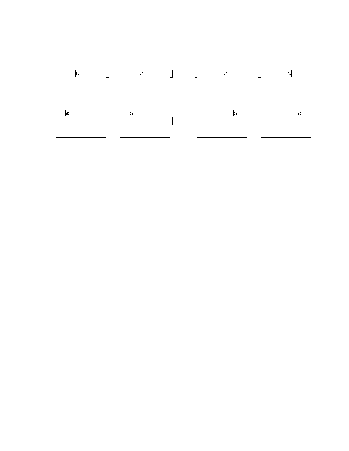
Here are the DIPSWITCHES. There are two switches on each little package or pair and two packages or pairs on each card
and two cards (channel one and channel two). The two switches should always be opposite - one ON and one OFF. UP is
ON.When (TOPPAIRS) the switches closest to the frontpanel areUP and ON and (BOTTOM PAIRS) theswitches closest
to the front panel are DOWN and OFF the 1/4" jacks are set up for +4 dBu levels.When (TOP PAIRS) the switches closest
to the front panel are DOWN and OFF and (BOTTOM PAIRS) the switches closest to the front panel are UP and ON the
1/4"jacksare setupfor -10dBv levels.The latter increasestheinput gainanddecreases theoutputlevel. The pairof switches
closesttothetopofthecardsettheinputgainandthepairclosesttothebottomsettheoutputlevels.Ontheseoutputswitches,
if both are OFF then you lose output to the 1/4" jack. If both are ON important parts of the circuit will be shorted together
and the unit will oscillate.
5) Removing individual EQ cards: You have to remove the top perforated panel first. Each card has a short ribbon cable
from the toggle switch board to the EQ card. You have to pull the ribbon connector from the EQ card before you pull out the
card.Once theribbon is free at theEQ cardend, unscrewthe twoallen keys holding the oblongblack anodizedpanel. Gently
pull the card towards you, being sure the ribbon cable is not catching on any of the EQ card components. To return an EQ
card into its slot, do the procedure in reverse. The only difference is that you need to watch the back of the card and align
the 14 pins into the connector and not offset.
Considering there are no active components on these EQ cards it is unlikely they will need to be repaired or removed. There
are a few minor differences between the 4 EQ cards and you should not change the order. These differences involve the
"voicing" to the 22Hz, 33Hz, 16K and 27K shelves. There is a possibility (plan) for Manley to introduce optional cards for
the Massive Passive at some point in the future. We have discussed,"Mastering stepped cards", "Active Constant Q cards",
"ClipperCards","NotchFiltercards"andothers.Duetotheenormousinterest in the "Mastering steppedcards"andtheywill
be the first to be done, however, remember that it is not possible in this design to really have constant 1dB or 1/2dB steps
becausethestepsizeisalways"scaled"tothebandwidth.Ifweusean11positionswitchsetupfor1/2dBstepsatthenarrowest
bandwidth, it results in only +/- 5.5 dB of available range and becomes less than +/-1.5 dB at wide bandwidths. On the other
hand, this is how all of the "Mastering Pultecs" we have built, also work. Over half of the mastering engineers have decided
to use the regular un-stepped version of the Massive Passive. The "Gain" pots seem to have reasonable resolution and
repeatability (twice what a conventional EQ does) and resetting is relatively easy. While step switches make a lot of sense
in some EQs, there may be less need in the Massive Passive and there are definite advantages of having the wide range of
control especially considering that the Massivo tends to not be as intrusive and "electronic colored" that we associate with
EQingingeneral.Theseoptions,ofcourse,willnotbefree,andsomeoptionsmayneedtobeorderedatpriortotheunitbeing
assembled. We suggest evaluating a stock unit before assuming that you need certain options.
The Massive Passive has been planned as an "EQ platform" that should accomodate special functions for a variety of
professional needs. There is no time-table planned for these cards and we will first annouce them, as usual, on our website
<www.manleylabs.com>. 18
DIP SWITCH SETTINGS
Channel 1 Channel 2

Equalizers
EQs range from simple bass and treble controls on a hifi system to
pretty tricky parametric EQs and 1/3 octave graphic EQs. As an
audiofreak,youhaveprobablytriedquiteafewEQsandhavegotten
both great results and sometimes less than great and you probably
have a favorite EQ. Now that you probably have a digital system,
youmay have questions about these digital EQsand the differences
between any analog and digital techniques. Let us begin at the
beginning,andthengetintosomerealtechniques.Whoinventedthe
first electronic tone control? Who knows? The first hints of “flat”
electronics came decades later. Simple bell and shelf EQs seem to
havebeenborninthe1930'sfor telephone company use.ThePultec
passive circuits came from that era at Western Electric. "Graphic
EQs"seem to have been invented in themid 60'sand were common
by the early 70's. A 19 year old prodigy, George Massenburg first
described, in a 1971 AES paper, the “Parametric Equalizer”.
All EQs do one thing — they can make some bands or areas of
frequencieslouderorquieterthanothers,manipulatingthefrequency
response.SpeakersandmicsdothattobutwenormallythinkofEQs
as something that allow us to alter the frequency response,
deliberately,withsomeknobsandbuttons-includingtheGUIones.
Some equalizers have no controls, they are part of a circuit and
generally are almost “invisible” to the user. A good example of this
is the EQ circuits used as “pre-emphasis” and “de-emphasis” used
for analog tape machines and radio broadcasting. The idea of these
is to boost the high frequencies before it hits the tape (or air), then
reduce the highs on playback (or reception). This reduces the hiss
andnoiseandusuallyallowsahottersignalwhichalsoimprovesthe
noise performance. These EQs usually have trimmers available but
wewouldrarelyconsiderusingthemforadjustingthetone.Instead,
theobjectistogetaruler-flatresponseatthispartofthe signalchain.
It is still called an equalizer. In fact the original definition of
“equalizer” was a device to restore all the frequencies to be equal
again, in other words, force the frequency response to be as flat as
possible.
Other common EQs that you are probably familiar with include the
common 1/3 octave graphic EQs with about 30 or 60 cheap sliders
across the front panel. These are usually a good tool for tuning a
room, but they may be a difficult thing to use for individual sounds.
Most1/3octEQsexcelwhenanumberoflittletweaksspacedacross
the spectrum are needed but not great for wide tonal changes. Too
many resonances. Some room tune experts are now relying on
parametricswithcontinuouslyvariablefrequencyknobsapparently
to "nail" the peaks. One reason 1/3 octave EQs have a bad name are
the"realtimeanalyzers"thatdisplayasingleaspectofthefrequency
response but without any time information, real or otherwise.
People often get much better results with warble tones, or tuning
rooms by ear with music. 1/3 octave EQs are appropriate for some
masteringtasksbutareprobablylessusedbecausetheytendtoscare
clients. The Massive Passive was not intended for room tuning.
Perhaps a future version with active constant Q mid bands in
combinationwithagood1/3octaveEQmaybe a very nicethingfor
that tricky job.
Parametric EQs come in lots of flavours, 3, 4 or 5 bands, most with
3 knobs per band and lots of variations. The earliest ones offered
only bell shapes, no shelves, no filters. Today's most common
variation has 2 mid bells with Q, a high shelf, low shelf and filters.
Wesee these in many consoles and in outboardEQs at a wide range
of prices. Almost all have limitations either in boost/cut range, Q
range, frequency range or overlap and audio performance.
Now we have a new breed of digital parametrics that have few
limitations-otherthandoesitactuallysoundgoodandisitavailable
for your format and is it stable and bug-free and is it a hassle to get
a signal in and out of it? Within their realm, some are getting good.
Passive EQs have come out over the the 60 (150) odd years for a
variety of different purposes. If we include all inductor/capacitor
based EQs the list includes API 560's, most of Rupert's designs up
tothe80's,allthePultecsandPultecclonesandanumberofhighend
1/3octavegraphics.Essentiallythelistincludesmostofthedesirable
vintage EQs that comprise many engineer's all-time favorites. The
Massive Passive is one of the only non-clone tube passive EQs and
the only one we know of that is 4 band quasi-parametric with boost
and cut on each band. There ain't nothin' like it.
Now there are a large number of enhancers, exciters, extenders and
multi-band compressors, that usually use combination of EQ,
distortion, dynamic effects and deliberate phase shift to create
effectsthat are related to EQ. They allseem tocome with a warning
"nottooveruse". The more"secretive"itis the moreweshould hold
itsuspect.Someofthese are boxesareusefulandoftena reasonable
alternative to conventional EQs. Sometimes, we think "if my EQs
and Limiters did what I wanted, then I sure wouldn't use this". We
hope that the Massivo helps towards this quest. If you like what the
magic boxes do, use them, but carefully because the results are
rarely reversible.
What most EQ's have in common is in the shapes of the shelves.
Almost all shelves can be designated as "first order" which means
that a single capacitor (or inductor) is used to shape the frequency
response. Second order implies two components, etc. A first order
filter is generally 6 dB/oct, second order should be 12 dB/oct, third
order18,etc.ShelfEQsneverquitegetto6dB/octandatthesteepest
point seem to be 4.5 dB/oct which is pretty gentle and why a 10K
boost seems to affect mids. Bell curves are normally second order
butarrangedtocreateadampedresonance.Onafirstordershelf,the
capacitor may be surrounded by any number of components to
create gain or to simulate an inductor or for other purposes. These
other components are a large reason why different EQs sound
different, but that single capacitor sets up a frequency response
curve that is very similar for almost all EQs. The shelves on the
Massive Passive combine a first order shelf with a variable depth
second order bell. At wide bandwidths it acts first order and at
narrow bandwidths approaches third order. We have played with
truesecondandthirdordershelveswithreal12and18dB/octslopes
and they sound pretty damn good. When you boost or cut a band of
frequencies,withasteeperslope,youaffect thefrequenciesthatyou
are aiming for, with much less action on other frequencies that you
didn’t intend to touch. Of course, to build an EQ like this with
frequency selection (even more need) the component cost and
complexity rises fast.
The future of EQs may bring us bells where each side (high & low)
plusthe top "flatness"can be adjustedseparately. Weare beginning
to see variations of shelves in plug-ins but so far it is just Tom
copying Dick who mimmicked an analog circuit by Harry. Perhaps
another parameter would be nice like, a sepately adjustable phase
shiftor distortion.Andifwecouldbendtherulesofnatureandhave
a non-resonant bell with zero ringing, we might have something
trulynewtohear.Itwouldbeverytransparentbutprobablyquiteun-
natural sounding. There is validy to "physical modelling" even in
analogEQcircuits."Natural"iskindaniceandveryeasytolistento.
19

EQ TECHNIQUE
One of the best things about almost all EQs is that you don’t really
need an instruction manual. You plug it in, turn a few knows and
when nothing happens you take it out of “bypass” and the rest is
easy.Youjustkeeptwiddlinguntilitsoundslikeyouwantitto.Most
digital devices like synthesizers and reverbs tend to get a lot of use
from the included presets. Most guys just don’t want to get into that
kindof “programming”.EQs arethe oppositewhere most guys will
ignorethe presets and start fromscratch or flat. This section may be
mosthelpfulforthemusiciannon-engineers, and maybeapplicable
to EQs in and music engineering in general. There are no real rules
here, just hints, suggestions and bits of other peoples wisdom.
Not so long ago, in order to get your chance at the console, you had
to follow the path from cleaning toilets, to making coffee, to
assisting, to engineering to producing. It cost years of micro-
paychecks and humble pie. Not so anymore. If you want your turn
attheconsole,youbuyaconsoleorbethemainemployeeataprivate
studio.Thereweresomebenefitsofwatchingtheoldpro’smakethe
gear sound great and being able to ask how and why. What we hope
to do here is be a small substitute for those who didn’t get that
opportunity. Specific settings for EQs are different for different
situations.SomeoftheseexamplesdriftabitfromjustEQingbutwe
include them for reference and to make EQing less of a fixer.
LiveSound:Inthisauthor’sexperience,livesoundusuallyrequired
the most drastic and heavy handed EQ. Every factor contributes to
this: Not the greatest mics, lots of leakage, feedback, strange
soundingstagesandrooms,questionablehousespeakers.Noluxuries
like mic positioning, just a quick sound-check (sometimes) and the
doors open. Tapes from live shows are almost as tough. If you are
accustomed to studio recording and clean tracks, you may need to
adjustyourtechniquesinahurry.Sometimes,yougetthesewonderful
clean tapes with a lot of energy. These tapes should be easy. Other
tapes can be pretty messy. Some of your usual studio tricks are not
working this time. With these tapes, you just might try taking the
“house mixer” approach. Pull down the effects, there’s too much
leakage, and dig in with those EQs. It might help to start out with a
good “fader only” mix and avoid using those “solo” buttons until
yougettheEQroughedout.Gatesmayhelp,butmaybeaudibleand
disconcerting if the leakage is gruesome. You might have to write
mutesearlyandavoidtoomuchcompression.EQingthevocalsmay
causealotofleakageproblemsifyouboostlowsorhighssignificantly.
If you get a raw tape with virtually no EQ or compression when it
wasrecordedyou mayneedtouse"unusual"andmoreEQonmany
ofthetracks. Usually,thebest approachisto tryto smooth itout but
not kick it into submission, but remember, this is raw and may need
more help than studio tracks.
Tracking the band: (in the studio) A bunch of musicians, a bunch
ofmics, andtypically not a bunch of budget. Well,at leastyou have
some good mics. By far, the best way to EQ at this stage is to use
those good mics to your advantage. With the right mic and the right
position,verylittleconsoleEQisneeded.Usetheroomsappropriate
to the instrument and use separation to control unwanted spillage,
get the instruments physically sounding awesome (we wish), then
usethemicstocreateanaturalpicturewithrealroomambiance.The
betterthemictechnique,thelessEQthatwillbeneeded.Infact,with
less fix-it EQ, the easier it will be to finesse your available EQ . Hit
"Record", finesse it in the mix. More important to get the vibe, than
to burn out the band doing sound checks and tweaks.
If mic choice is a mystery, you might want to research some Steve
AlbiniorGeorgeMassenburginterviews.Ratherthanguesswrong,
some engineers compare 3 or 4 probable choices. Some choose the
mic that minimizes EQing later, some hear the mic’s transient or
dynamiccharacterandanticipatewhatsomeEQshouldaddinanice
way. Some guys have been there, done that, and know exactly what
theylike anddon’t, (but always seem tobe readyto learn more) and
bring in their own mics to get thier trademark sound.
Thecloseryouhavethemictosomeinstruments,themorelikelyEQ
will be needed and less likely you will get both some great leakage
and some not-so-good leakage. Close miking is better when you
intendto sculptthe sound.Distant miking is better for documenting
(recording) the music. On vocals and room mics, many use big
diaphragm condenser tube mics where you want smoothness and
richness. Some tube mics may add a bit of “attitude” and
aggressiveness and some are very “real” sounding. The biggest
differences in this family of mics is the two lowest and highest
octaves and what the back of the mic sounds like. Small diaphragm
condensers can be fast, bright, clear but sometimes brittle, hard or
thin.Some are quite good for acoustic instruments,cymbals andhi-
hats.Watchout,thereisawidevariationinmaximumSPLandnoise
with these. Of course most engineers favor large diaphragm
condensers and typically use FET types on drums and guitars. The
pattern choice is an important tool. Remember that the proximity
effect(lowboosting)isbiggestin“figure8”,moderatein“cardioid”
and non-existent in “omni”. It is worth listening to both the “room
tone” and instrument in the 3 main patterns - it's often surprising.
The low roll-off (HP) should be used where ultra-lows are not
needed or wanted and the filter kills some of the room noise and air
conditioningrumble.Dynamicmicsaremorecommonlyusedclose
for guitar amps, drums and sometimes horns. Ribbon mics have
theirresonanceinthedeeplowsandtypicallyhaveasoftishtopend.
They seem to have a more “ear-like” dynamic range. This makes
them a superb choice for raunchy guitar amps, horns and anything
that may be too edgy. Some are cardioid and some figure 8. Try
using2 figure 8'sas a stereopair (rotated 90 degreesala Blumlein).
Officially, miking technique is not EQing but it does some of the
same things and does it in the beginning. This makes EQing easier
and elegant.
Whenyou dohave toEQ, theband tracking session is the time to be
careful and conservative. Most experienced pro engineers don’t
wing it here. Safe, fast, ready, recorded. It may not sound as
“slamming” as it could be, but wait, it still gets overdubs and a real
mix. Engineers who don’t play it safe at the right time tend to find
other occupations like accounting. You can fix the EQ and
Compression later particularly if you are working digital. You may
want to save those initial more-or-less flat tracks though, for a few
days or weeks, just in case.
Another little detour. There always seems to be some fascination
withre-capturingsomeofthat60’sandevenearly70’ssound.These
were the days of 4 track and 8 track analog machines and no time-
code or sync systems. They didn’t have a lot of gear, so it was
important to have the good stuff. Much of it was vacuum tube or
passive. Overdubs were a luxury but they could mix those 4 or 8
tracks to mono or stereo and bounce them over to another machine.
It was analog tape so you couldn’t do it more than a few times. So,
what are the priorities when you record that way?
20
This manual suits for next models
2
Table of contents
Other Manley Stereo Equalizer manuals


Popular Stereo Equalizer manuals by other brands


Kenwood
Kenwood GE-7030 instruction manual

Extron electronics
Extron electronics Equalizer HDMI 101 Specifications

Gyraf Audio
Gyraf Audio G14 user manual

Kenwood
Kenwood KGC-6042 instruction manual

Kenwood
Kenwood GE-90 instruction manual

Sound Performance Lab
Sound Performance Lab TUBE VITALIZER 9530 user manual