Manley MASSIVE PASSIVE STEREO TUBE EQ User manual

OWNER’S MANUAL
MANLEY
MASSIVE PASSIVE
STEREO TUBE EQ

CONTENTS
SECTION PAGE
INTRODUCTION 3
BACK PANEL & CONNECTING 4
FRONT PANEL 5-8
CREDITS 8
NOTES ON THE MASTERING VERSION 9
THE MASSIVE PASSIVE
BEGINNINGS, THE SUPER PULTEC 10
THE PASSIVE PARAMETRIC 11
WHY PASSIVE, WHY PARALLEL 12
PHASE SHIFT, WHY TUBES 13
CURVES 14-17
TUBE LOCATIONS, ETC 18, 19
EQUALIZING
EQUALIZERS (GENERAL) 20
EQUALIZER TECHNIQUES 21-25
TRANSLATIONS 26
TROUBLESHOOTING 27, 28
MAINS CONNECTIONS 29
SPECIFICATIONS 30
SPECIFICATIONS - MASTERING VERSION 31
APPENDIX 1 - TEMPLATE FOR STORING SETTINGS 32
APPENDIX 2 - MASTERING VERSION TEMPLATE 33
rev5/9/11cd

INTRODUCTION
THANK YOU!...
for choosing the Manley MASSIVE PASSIVE STEREO TUBE EQUALIZER. This EQ is sup-
posed to be somewhat different from any EQ you may have used before , as well, this manual may
be a bit unusual in that you may nd it worthwhile to read. Even though at rst glance the Massive
Passive looks fairly conventional, you should take an hour and read this manual before you jump to
conclusions or confusions. The usual stuff like precautions, hook-up instructions, and operational in-
formation is here but also explanations about how and why this is an unusual animal and hints of how
you may nd different settings than you are used to being the key to getting the most out of this box.
There is even a little section of EQ hints or techniques for those who may nd that info useful.
As you use this EQ, probably a number of descriptive words may come to you. It has been called
“organic”, “natural”, “smooth”, “liquid”, “powerful”, “sweet”, and “the mother of all EQs”. There is
no single reason why it sounds the way it does but more of a synergy of the advantages of passive
EQ, the parallel topology, the tube/transformer ampliers, the unique shelves and, of course, Manley’s
construction style and use of premium components. Like the Manley Variable MU, we have found the
Massive Passive can easily make anything sound better. Perhaps the combination of the “Vari-MU”
and the “Massivo” is the killer combination for music. You may nd yourself using it everything. Any
gear that you prefer to use on every sound is a sure sign you bought the right piece.
GENERAL NOTES
LOCATION & VENTILATION
The Manley MASSIVE PASSIVE must be installed in a stable location with ample ventilation. It
is recommended, if this unit is rack mounted, that you allow enough clearance on the top of the unit
such that a constant ow of air can move through the ventilation holes. Airow is primarily through
the back panel vents and out through the top.
You should also not mount the Massive Passive where there is likely to be strong magnetic elds such
as directly over or under power ampliers or large power consuming devices. The other gear’s fuse
values tend to give a hint of whether it draws major power and is likely to create a bigger magnetic
eld. Magnetic elds might cause a hum in the EQ and occasionally you may need to experiment with
placement in the rack to eliminate the hum. In most situations it should be quiet and trouble free.
WATER & MOISTURE
As with any electrical equipment, this equipment should not be used near water or moisture.
SERVICING
3
The user should not attempt to service this unit beyond that described in the owner’s manual. Refer all
servicing to your dealer or Manley Laboratories. The factory technicians are available for questions
by phone Fill in your warranty card! Check the manual - Your question is probably anticipated and
answered within these pages......

9
10
11
12
CHANNEL 2
1 2 3 4
First connect all the cables, then turn on the power, wait 30 seconds, then have fun, as if we had to tell you....
1) POWER CONNECTOR. First verify the POWER SWITCH on the front panel is off (CCW). Use the power cable supplied with
your Massive Passive. One end goes here and the other end goes to the wall outlet. You know all this.
2) VOLTAGE LABEL (ON SERIAL STICKER). Just check that it indicates the same voltage as is normal in your country. It should
be. If it says 120V and your country is 220V, then call your dealer up. If it says 120V and you expect 110 it should work ne.
3) FUSE. Unplug the power cable rst. The Fuse Cap needs a push then turn a quarter twist CCW to pull off. Fuses are meant to
“blow” when an electrical problem occurs and is essentially a safety device to prevent res, shocks and big repair bills. Only replace it
if it has “blown” and only with the same value and type (2A slow-blow for 120V, 1A slow-blow for 220V). A blown fuse either looks
blackened internally or the little wire inside looks broken. A blown fuse will prevent all the LEDS from lighting and will prevent any
power and audio.
4) GROUND TERMINALS. You probably don’t need to worry about these. Normally there is a metal strip joining CIRCUIT and
CHASSIS Grounds. This is the rst place to look if you get a hum. Make sure the strap hasn’t fallen off or use a piece of wire to join
the terminals. The CIRCUIT Ground is the internal audio ground (including the 1/4” jack sleeves). The CHASSIS Ground is the metal
chassis, third pin electrical ground and pin 1 of the XLRs. Some studios use special grounding practices and these terminals are meant
to make it easy to hook up this unit for a wide variety of installations. They also help with troubleshooting hum problems.
5) PHONE JACK INPUT. (Channel One or Left) Accepts balanced or unbalanced sources. Factory set-up for +4dBu pro levels.
There are some DIP switches internally that can change this to -10dBv semi-pro or hi- levels. The pin out is as follows: Tip = Posi-
tive = Hot, Ring = Negative = Low or ground, Sleeve = Circuit Ground. If you use TRS plugs be sure that the ring is connected to the
negative or ground and not “open”. Input impedance is 20K ohms. See page 16 & 17 for the DIP Switch details.
6) XLR JACK INPUT. (Channel One or Left) Accepts balanced or unbalanced sources. Only for +4dBu pro levels. The DIP switches
have no effect on the XLRs. The pin out is as follows: PIN 2 = Positive = Hot, PIN 3 = Negative = Low or ground, PIN 1 = Chassis
Ground. Be sure that the PIN 3 is connected to the negative or ground and not “open” or a 6dB loss or loss of signal will happen. In
general, the XLRs and +4 pro levels are slightly preferable over phone plugs especially if gold plated matching XLRs and good cable
are used.
7) XLR JACK OUTPUT. (Channel One or Left) Transformer Balanced and Floating. Only for +4dBu pro levels. The DIP switches
have no effect on the XLRs. The pin out is as follows: PIN 2 = Positive = Hot, PIN 3 = Negative = Low or ground, PIN 1 = Chassis
Ground. Be sure that the PIN 3 is connected to the negative or ground and not “open” or a complete loss of signal will happen. Output
impedance is 150 ohms and output levels can reach +37 dBv (hot) which may distort the next piece in the chain.
8) PHONE JACK OUTPUT. (Channel One or Left) Unbalanced output only. Factory set-up for +4dBu pro levels. There are some
DIP switches internally that can change this to -10dBv semi-pro or hi- levels (with a phase reverse). The pin out is as follows: Tip
= Positive = Hot, Sleeve = Circuit Ground. If you use TRS plugs be sure that the ring is connected to the negative or ground and not
“open”. See page 16 & 17 for the DIP Switch details.
9) PHONE JACK INPUT. (Channel Two or Right) Same as 5 above.
10) XLR JACK INPUT. (Channel Two or Right) Same as 6 above.
11) XLR JACK OUTPUT. (Channel Two or Right) Same as 7 above.
12)PHONE JACK OUTPUT. (Channel Two or Right) Same as 8 above.
CHANNEL 1
5
6
7
8
THE BACK PANEL
4

1) The Power Switch: First things rst, turn it clockwise to power up the unit. There is no “power on LED”, instead you can use any
of the Boost / Off / Cut switches in Boost or Cut and they light immediately with power on. There is a “warm-up” circuit that forces the
unit into “Bypass” for about 20 seconds, to prevent big thumps from hitting your speakers. This also prevents the blue LEDs that indi-
cate “EQ IN” from lighting up for that 20 seconds. This is not a total hardwire bypass - if power is not on, the unit will not pass audio.
At trade shows, we have seen a few people turn the “Power Switch” by accident, perhaps thinking it was a tone control. Not knowing,
there is a “warm-up” circuit, and seeing no blue light action, they thought they may have broken the unit. The lack of a “power LED” is
just one of the deliberate ideosyncracies. 4 reasons: there wasn’t a great place to put one, it was redundant with 16 boost/cut LEDs (we
were laughing at other panels with dozens of lit LEDs and a fast turn-on LCD screen also sporting a big power LED), and this unit is
meant for professionals that we assume can plug in a piece of gear, see (or feel) the switch and turn it on, and it may annoy those who
want all gear to be just “normal” ;-)
2) EQ IN buttons: Push to activate the EQ circuits. The buttons glow blue when EQ is IN including the Filters and Gain Trims. The
“warm-up” circuit prevents both EQ to be IN and the buttons from lighting when it rst gets powered up. In “bypass” (un-lit) the tubes
are not in circuit but the input amplier and balanced output transformer are in circuit. Yes, real blue LEDs.
3) Gain Trims: Intended to help match levels between “Bypass” and “EQ IN” modes so that the EQ effect can be more accurately
judged. It is difcult to compare if the level jumps up or down and easy to prefer EQ when mostly it is just louder. These trims only
have a small range of -6 to +4 dB of gain. With drastic EQ there may not be enough range to match levels but with drastic EQ this kind
of comparison is of little use. The range is small to allow easier and ner adjustments.
4) Low Pass Filters: They pass lows and chop highs. There is a separate lter for each switch setting and they only share the switch
and one resistor. The lters are entirely passive and “inserted” between the boost sections and cut sections. The 18kHz lter is probably
most useful for warming up digital. It seems to remove some irritating super-sonic noise associated with digital to analog converters. It
is designed as a modied eliptical lter down 60dB one octave up (36kHz) on paper but in real life “only” drops about 40 dB. It is at
within 0.5dB up to 16kHz then very steeply drops. It is sonically subtle. 12kHz position can be considered general purpose hiss killing.
It is also very at up to 11kHz and drops at 30 dB/octave. 9kHz, 7.5kHz & 6 kHz. These are intended for more creative sound sculpt-
ing than as utility lters. They have a 1.5 to 2 dB bump or boost right before they cut at 18dB/octave. This helps compensate for the
percieved loss of highs while still allowing deep HF cuts. This gives them a little color and edge as opposed to just dullness. You may
nd they help remove some of that buzzy super high distortion of cranked guitar rigs as well as help some synth and bass sounds. They
are also intended to help with “effects” such as “telephone sound” and vintage simulations and for some techno, rap and industrial style
music.
5) High Pass Filters: They pass highs and chop lows. There is a separate lter for each switch setting and they only share the switch
and one resistor. The lters are entirely passive and “inserted” between the boost sections and cut sections. They are all 18dB/octave
(most modern lters are 12), with no bumps and no resonances. We use a large, low DCR, custom inductor. The 22Hz is very subtle
and is designed to remove sub-sonic frequencies that may have been boosted by previous EQ. Most signal below 25Hz is only good
for testing or messing up sub-woofers. You may not hear the effect in the studio, but often you can see it on the meters. Now that sub-
woofers are becoming common in autos and consumer systems, we are hearing more complaints of excess lows and LF garbage. This
lter is in response to these concerns and requests from mastering engineers. The 39Hz lter can be used similarly, but may be audible
with some material. This lter, as with the others, can be used with the normal boost/cut sections for a more tailored low EQ. This can
allow bigger and more effective LF boosts while minimising the side-effects of excessive woofer excursions and unwanted audible
LF noise like air conditioner or subway rumble. The 68Hz lter is also general purpose and ideal for most vocals and pop removal.
Also good in combination with shelves. 120 and 220Hz lters are intended for garbage removal, sonic sculpting, and effects. 120 is
useful for some vocals. The 220 is for some close miked hi-hats and percussion instruments. Yup, 220Hz tends to be drastic and only
occasionally valuable.
Check out the curves on page 16 for a little more detail on these lters.
5
THE FRONT PANEL
1K2
1K8
27K
12K
8K2
5K6
3K9
2K7
1K8
1K2
820
560220
330
470
680
1K
1K5
2K2
3K3
4K7
6K8
10K
FREQUENCY FREQUENCY
2K7
FREQUENCY
3K9
820
560
390
270
180
120
82
FREQUENCY
680
1K
470
330
220
150
68
47
33
22
100 100
22
33
47
68
150 220
330
470
1K
680
FREQUENCY
82
120
180
270
390
560
820
3K9
FREQUENCY
2K7
FREQUENCYFREQUENCY
10K
6K8
4K7
3K3
2K2
1K5
1K
470
330
220 560
820
1K2
1K8
2K7
3K9
5K6
8K2
12K
27K
1K8
1K2
BANDWIDTH
20
020
0
BANDWIDTH
20
0
BANDWIDTH
20
0
BANDWIDTH
20
0
BANDWIDTH
20
0
BANDWIDTH
20
0
BANDWIDTH
20
0
16K 16K
DB
BANDWIDTH
DB DB DB DB DB DB DB
680
MASSIVE PASSIVE
STEREO EQUALIZER
12K
7K5
22
39 68
120
220
18K
00
POWER
9K
OFF 6K
7K5
OFF
9K
18K
12K
OFF OFF 220
120
68
39
22
GAIN
6K
LOW
PASS
HIGH
PASS
IN IN
+4
-6 -6 +4
BOOST
CUT
SHELF
BELL
220 ±10K82 ±3K922 ±1K 560 ±27K
BELL
SHELF
CUT
OUT
BOOST BOOST
OUT
CUT
SHELF
BELL BELL
SHELF
CUT
OUT
BOOST
OUT
BELLCUT
OUT
SHELF
BOOST
560 ±27K
BELLCUT
OUT
BOOST
220 ±10K
BELLCUT
OUT
BOOST
82 ±3K9
CUT BELL
OUT
SHELF
22 - 1K
BOOST SHELFSHELF
1) The Power Switch: First things first, turn it clockwise to power up the unit. There is no "power on LED", instead you can
use any of the Boost / Off / Cut switches in Boost or Cut and they light immediately with power on. There is a "warm-up" circuit
that forces the unit into "Bypass" for about 20 seconds, to prevent big thumps from hitting your speakers. This also prevents
the blue LEDs that indicate "EQ IN" from lighting up for that 20 seconds. This is not a total hardwire bypass - if power is not
on, the unit will not pass audio. At trade shows, we have seen a few people turn the "Power Switch" by accident, perhaps
thinking it was a tone control. Not knowing, there is a "warm-up" circuit, and seeing no blue light action, they thought they
may have broken the unit. The lack of a "power LED" is just one of the deliberate ideosyncracies. 4 reasons: there wasn't a
great place to put one, it was redundant with 16 boost/cut LEDs (we were laughing at other panels with dozens of lit LEDs
and a fast turn-on LCD screen also sporting a big power LED), and this unit is meant for professionals that we assume can plug
in a piece of gear, see (or feel) the switch and turn it on, and it may annoy those who want all gear to be just "normal" ;-)
2) EQ IN buttons: Push to activate the EQ circuits. The buttons glow blue when EQ is IN including the Filters and Gain Trims.
The "warm-up" circuit prevents both EQ to be IN and the buttons from lighting when it first gets powered up. In "bypass" (un-
lit) the tubes are not in circuit but the input amplifier and balanced output transformer are in circuit. Yes, real blue LEDs.
3) Gain Trims: Intended to help match levels between "Bypass" and "EQ IN" modes so that the EQ effect can be more
accurately judged. It is difficult to compare if the level jumps up or down and easy to prefer EQ when mostly it is just louder.
These trims only have a small range of -6 to +4 dB of gain. With drastic EQ there may not be enough range to match levels
but with drastic EQ this kind of comparison is of little use. The range is small to allow easier and finer adjustments.
4) Low Pass Filters: They pass lows and chop highs. There is a separate filter for each switch setting and they only share the
switch and one resistor. The filters are entirely passive and "inserted" between the boost sections and cut sections.
The 18kHz filter is probably most useful for warming up digital. It seems to remove some irritating super-sonic noise
associated with digital to analog converters. It is designed as a modified eliptical filter down 60dB one octave up (36kHz) on
paper but in real life "only" drops about 40 dB. It is flat within 0.5dB up to 16kHz then very steeply drops. It is sonically subtle.
12kHz position can be considered general purpose hiss killing. It is also very flat up to 11kHz and drops at 30 dB/octave.
9kHz, 7.5kHz & 6 kHz. These are intended for more creative sound sculpting than as utility filters. They have a 1.5 to 2 dB
bump or boost right before they cut at 18dB/octave. This helps compensate for the percieved loss of highs while still allowing
deep HF cuts. This gives them a little color and edge as opposed to just dullness. You may find they help remove some of that
buzzy super high distortion of cranked guitar rigs as well as help some synth and bass sounds. They are also intended to help
with "effects" such as "telephone sound" and vintage simulations and for some techno, rap and industrial style music.
5) High Pass Filters: They pass highs and chop lows. There is a separate filter for each switch setting and they only share the
switch and one resistor. The filters are entirely passive and "inserted" between the boost sections and cut sections. They are
all 18dB/octave (most modern filters are 12), with no bumps and no resonances. We use a large, low DCR, custom inductor.
The 22Hz is very subtle and is designed to remove sub-sonic frequencies that may have been boosted by previous EQ. Most
signal below 25Hz is only good for testing or messing up sub-woofers. You may not hear the effect in the studio, but often
you can see it on the meters. Now that sub-woofers are becoming common in autos and consumer systems, we are hearing more
complaints of excess lows and LF garbage. This filter is in response to these concerns and requests from mastering engineers.
The 39Hz filter can be used similarly, but may be audible with some material. This filter, as with the others, can be used with
the normal boost/cut sections for a more tailored low EQ. This can allow bigger and more effective LF boosts while minimising
the side-effects of excessive woofer excursions and unwanted audible LF noise like air conditioner or subway rumble.
The 68Hz filter is also general purpose and ideal for most vocals and pop removal. Also good in combination with shelves.
120 and 220Hz filters are intended for garbage removal, sonic sculpting, and effects. 120 is useful for some vocals. The 220
is for some close miked hi-hats and percussion instruments. Yup, 220Hz tends to be drastic and only occasionally valuable.
Check out the curves on page 16 for a little more detail on these filters.
12345
5
THE FRONT PANEL

1) BOOST / OUT / CUT, TOGGLE. Each band has individual toggles to select whether that band will boost or cut or be bypassed.
“OUT” is a hardwire bypass for that band. Unlike most EQs, you must select boost or cut for each band. There are several good
reasons for this arrangement. First, because the boost part of the circuit is in a different place than the cut part because it is passive,
this allows us to use the same components in both sections but doing essentially opposite functions. The conventional arrangement
of a boost/zero/cut pot (baxandall) circuit was avoided to really make it passive. This switch also allows twice the resolution of the
“GAIN” pot and a much more accurate “zero”. The center detent of conventional EQs is rarely the “electrical” center of the pot so
what you expect is zero is often a little EQed. This toggle allows some of us, who use dip EQ to reduce offending frequencies to
verify those frequencies in “Boost” and then switch to “Cut”. Finally, it allows us to bypass each band individually, without losing
our “GAIN” pot setting rather than resetting a band to zero or bypassing the entire EQ.
2) SHELF & BELL. The two lowest (leftmost) bands can each be a special Low Shelf or conventional Bell shape. The two highest
(rightmost) bands can each be a special High Shelf or conventional Bell shape. Shelf & Bell describe the EQ’s shape. We included
some diagrams to help visualize these curves. Bell curves focus their boost and cut at given frequency and the further away we get
from that frequency, the less boost or cut. The bell curves on the Massivo are moderately wide and the “Bandwidth Control” does
not have a lot of range and it also affects the maximum boost and cut (like a Pultec). Shelf slopes generally boost (or cut) towards
the highs or lows (thus high shelves and low shelves). These are not to be confused with “high or low lters” which purely cut above
or below a given frequency. Shelves also have gain or dB controls which allow you to just boost or cut a little bit if desired - lters
never have these controls. The Massive Passive allows each of the 4 bands to be switched to shelf. The two mid shelves are almost
the same as the outer ones but just have other (interleaved) frequency choices. For example, you can set up the mid-high shelf to
start boosting at 3K3, say 4 dB, then apply another high shelf to boost 12K, say for 10 dB, which provides a few gentle gradual
steps. BTW, the maximum boost in the example is 10 dB (not 14) and occurs around 20 kHz. You may notice that as you switch
between bell and shelf the amount of “grab” may seem to be less in shelf. Not really, both are capable of 20 db boosts but towards
the extremes that boost may be sub-sonic or super-sonic because we “spec” the shelf at the 1/2 way point (10 dB), not the 3 dB down
(or up) or maximum point. When you choose frequencies closer to the mids this “effect” is much less however if the “bandwidth” is
medium to narrow the “effect” is more pronounced. Most EQs don’t allow one to switch from bell to shelf and don’t have a function-
ing “bandwidth” in shelf mode and this may be understandably unfamiliar ground.
3) GAIN. This sets the boost and/or cut depth or amount and works with the BOOST, OUT, CUT, TOGGLE. FLAT is fully counter-
clockwise not straight up “12:00” like most EQs. It is more like a Pultec in this regard. Maximum boost or cut is fully clockwise and
can be up to 20 dB - but not necessarily. There is a fair amount of interaction with the BANDWIDTH control. The maximum of 20
dB is available in Shelf modes when the Bandwidth is CCW and is about 12 dB when the Bandwidth is CW. The maximum of 20 dB
is available in Bell modes when the Bandwidth is CW and is about 6 dB when the Bandwidth is CCW. At straight up “12:00” in Bell
mode “narrow” expect about 8 dB of boost or cut. In other words, you shouldn’t expect the markings around the knob to indicate
a particular number of dBs. Many Eqs are this way. On the other hand, this interaction is the result of natural interactions between
components and tends to “feel” and sound natural as opposed to contrived.
These 4 GAIN controls have some interaction with each other unlike conventional EQs. It is a parallel EQ rather than the far more
common series connected style. If you set up all 4 bands to around 1kHz and boosed all 20 dB, the total boost will be 20 dB rather
than 80dB (20+ db of boost and 60 dB into clipping). This also implies, that if you rst boost one band, that the next three will not
seem to do anything if they are at similar frequencies and bandwidths. Virtually all other parametrics are both series connected and
designed for minimal interaction, which seems to be quite appealing if you wear a white lab coat with pocket protectors ;.) Actually,
there are valid arguements for those goals and there are denately some applications that require them. However, there is also a valid
point for an EQ that is substantially different from the “norm”, and for audio toys that have artistic merit and purpose and not just
scientic interest or gimmickry. We tried to balance artistic, technological and practical considerations in the Massivo, and offer both
some new and old approaches that appealed to the ears of recording engineers (and our own ears).
6
OUT
BELL
SHELF
CUT
BOOST
DB
020
BANDWIDTH
100
22
33
47
68
150 220
470
1K
680
FREQUENCY
BOOST
OUT
CUT
SHELF
BELL
560 - 27K
DB
16K
020
BANDWIDTH
FREQUENCY
560
820
1K2
1K8
2K7
3K9
5K6
8K2
12K
27K
22 - 1K
330
GAIN
CCW = FLAT
BANDWIDTH
CCW = WIDE
FREQUENCY
SELECT
BOOST
OFF
CUT
BOOST
OFF
CUT
LOW SHELF
BELL
HIGH SHELF
BELL
1
2
3
4
5
1) BOOST / OUT / CUT, TOGGLE. Each band has individual toggles to select whether that band will boost or cut or be
bypassed. "OUT" is a hardwire bypass for that band. Unlike most EQs, you must select boost or cut for each band. There are
several good reasons for this arrangement. First, because the boost part of the circuit is in a different place than the cut part because
it is passive, this allows us to use the same components in both sections but doing essentially opposite functions. The conventional
arrangement of a boost/zero/cut pot (baxandall) circuit was avoided to really make it passive. This switch also allows twice the
resolution of the "GAIN" pot and a much more accurate "zero". The center detent of conventional EQs is rarely the "electrical"
center of the pot so what you expect is zero is often a little EQed. This toggle allows some of us, who use dip EQ to reduce offending
frequencies to verify those frequencies in "Boost" and then switch to "Cut". Finally, it allows us to bypass each band individually,
without losing our "GAIN" pot setting rather than resetting a band to zero or bypassing the entire EQ.
2) SHELF & BELL. The two lowest (leftmost) bands can each be a special Low Shelf or conventional Bell shape. The two
highest (rightmost) bands can each be a special High Shelf or conventional Bell shape. Shelf & Bell describe the EQ's shape. We
included some diagrams to help visualize these curves. Bell curves focus their boost and cut at given frequency and the further
away we get from that frequency, the less boost or cut. The bell curves on the Massivo are moderately wide and the "Bandwidth
Control" does not have a lot of range and it also affects the maximum boost and cut (like a Pultec). Shelf slopes generally boost
(or cut) towards the highs or lows (thus high shelves and low shelves). These are not to be confused with "high or low filters"
which purely cut above or below a given frequency. Shelves also have gain or dB controls which allow you to just boost or cut
a little bit if desired - filters never have these controls. The Massive Passive allows each of the 4 bands to be switched to shelf.
The two mid shelves are almost the same as the outer ones but just have other (interleaved) frequency choices. For example, you
can set up the mid-high shelf to start boosting at 3K3, say 4 dB, then apply another high shelf to boost 12K, say for 10 dB, which
provides a few gentle gradual steps. BTW, the maximum boost in the example is 10 dB (not 14) and occurs around 20 kHz. You
may notice that as you switch between bell and shelf the amount of "grab" may seem to be less in shelf. Not really, both are capable
of 20 db boosts but towards the extremes that boost may be sub-sonic or super-sonic because we "spec" the shelf at the 1/2 way
point (10 dB), not the 3 dB down (or up) or maximum point. When you choose frequencies closer to the mids this "effect" is much
less however if the "bandwidth" is medium to narrow the "effect" is more pronounced. Most EQs don't allow one to switch from
bell to shelf and don't have a functioning "bandwidth" in shelf mode and this may be understandably unfamiliar ground.
3) GAIN. This sets the boost and/or cut depth or amount and works with the BOOST, OUT, CUT, TOGGLE. FLAT is fully
counter-clockwise not straight up "12:00" like most EQs. It is more like a Pultec in this regard. Maximum boost or cut is fully
clockwise and can be up to 20 dB - but not necessarily. There is a fair amount of interaction with the BANDWIDTH control. The
maximum of 20 dB is available in Shelf modes when the Bandwidth is CCW and is about 12 dB when the Bandwidth is CW.
The maximum of 20 dB is available in Bell modes when the Bandwidth is CW and is about 6 dB when the Bandwidth is CCW.
At straight up "12:00" in Bell mode "narrow" expect about 8 dB of boost or cut. In other words, you shouldn't expect the markings
around the knob to indicate a particular number of dBs. Many Eqs are this way. On the other hand, this interaction is the result
of natural interactions between components and tends to "feel" and sound natural as opposed to contrived.
These 4 GAIN controls have some interaction with each other unlike conventional EQs. It is a parallel EQ rather than the far more
common series connected style. If you set up all 4 bands to around 1kHz and boosed all 20 dB, the total boost will be 20 dB rather
than 80dB (20+ db of boost and 60 dB into clipping). This also implies, that if you first boost one band, that the next three will
not seem to do anything if they are at similar frequencies and bandwidths. Virtually all other parametrics are both series connected
and designed for minimal interaction, which seems to be quite appealing if you wear a white lab coat with pocket protectors ;.)
Actually, there are valid arguements for those goals and there are definately some applications that require them. However, there
is also a valid point for an EQ that is substantially different from the "norm", and for audio toys that have artistic merit and purpose
and not just scientific interest or gimmickry. We tried to balance artistic, technological and practical considerations in the
Massivo, and offer both some new and old approaches that appealed to the ears of recording engineers (and our own ears).
6
THE 4 BANDS

4) BANDWIDTH. Similar to the “Q” control found in many EQs. A more accurate term here would be “Damping” or “Resonance”
but we used “Bandwidth” to stay with Pultec terminology and because it is a “constant bandwidth” (*) design rather than “con-
stant Q” and because of the way it uniquely works in both Bell and Shelf modes. In Bell modes, you will nd it similar to most Q
controls with a wider shape fully CCW and narrower fully CW. The widest Q (at maximum boost) is about 1 for the 22-1K band and
1.5 for the other 3 and the narrowest Q is about 2.5 to 3 for all of the bands and most of the frequencies. On paper, the bell widths
appear to have less effect than is apparent on listening and the sound is probably more due to “damping” or “ringing” and the way it
interacts with the gain. Also some people associate a wide bell on conventional EQs with more energy boost or cut, and at rst im-
pression the Massivo seems to work backward compared with that and narrow bandwidths give more drastic results. On the Massive
Passive a narrow bandwidth bells will allow up to the full 20 dB of boost (or cut) and wide bandwidths signicantly less at about 6
dB maximum.
In Shelf Modes the Bandwidth has a special function. When this knob is fully CCW, the shelf curves are very similar to almost all
other EQs. As you increase the Bandwidth control, you begin to introduce a bell curve in the opposite direction. So if you have a
shelf boost, you gradually add a bell dip which modies the overall shelf shape. At straight up, it stays atter towards the mid range,
and begins to boost further from the mids with a steeper slope but the nal maximum part of the boost curve stays relatively un-
touched. With the Bandwidth control fully CW, that bell dip becomes obvious and is typically 6dB down at the frequency indicated.
The boost slope is steeper and the maximum boost may be about 12 dB. These curves were modelled from Pultec EQP1-As and
largely responsible for the outrageous “phatness” they are known for. As you turn the Bandwidth knob (CW), it seems as if the shelf
curve is moving further towards the extreme frequencies, but mostly of this is just the beginning part of the slope changing and not
the peak. This also implies, that you may nd yourself using frequencies closer to the mids than you might be used to. These shelf
curves have never been available for an analog high shelf before and provide some fresh options.
5) FREQUENCY. Each band provides a wide range of overlapping and interleaving frequency choices. Each switch position is se-
lecting a different capacitor and inductor. Only the 22 and 33 Hz on the low band and the 16K and 27K in shelf mode deserve some
special explanation. These have been “voiced” a little different from the rest and are somewhat unique.
Why “modify” the way the 22, 33, 16K and 27K shelves work? When we specify that a low shelf is at 22 Hz, it means that only the
half-way point of the boost (or cut) is 22 Hz. If we dial up a 20 dB boost set at 22Hz then 22 Hz is half-way up the slope or boosted
10dB. The full amount of the boost (20 dB) is only kicking in around 2 Hz. This is dangerous and almost useless for anything
except whale music. Not only that, but now we have a Bandwidth control that seems to push the frequency lower, and at 12:00 es-
sentially attens the EQ at 22Hz. So we changed the Bandwidth control for those two lowest frequencies so that it acts as a HP lter
as you turn it CW and tends to prevent boosting excessive sub-sonic frequencies. To our ears, it seems to “tighten up” the shelf and
removes some of the sloppy looseness associated with those sub-sonics.
The 16kHz and 27kHz shelfs were also specially “voiced” for similar reasons. In this case, a 50kHz low pass lter prevents these
shelfs from helping recieve the local AM radio stations. The Bandwidth-Dip frequencies were lowered to about 8 kHz so that on a
single band, you would have more effective control between the balance of “air” and “sibilance”. In practice, it gives you a great
deal of air without the usual problem “esses” when you boost a lot of highs.
At extreme high and low frequencies (including 10K and 12K), you might get some unexpected results because of the Bandwidth/
Shelf function. For example, you can set up 20 dB of boost at 12K and it can sound like you just lost highs instead of boosting. This
happens when the Bandwidth control is more CW only and not when it is CCW. Why? You are creating a dip at 12K and the shelf
is only beginning at the fringes of audibility but the dip is where most of us can easily percieve. It takes a little getting used too the
way the controls interact. The reverse is also true, where you set up a shelf cut and you get a boost because of the Bandwidth control
being far CW. In some ways this simulates the shape of a resonant synthesizer lter or VCF except it doesn’t move. These wierd
highs are useful for raunchy guitars and are designed to work well with the Filters. There are a lot of creative uses for these bizarre
settings including messing up the minds of back-seat engineers. There is some example settings near the back page that may help to
show how different this EQ is.
_________________________________________________________________________________________________
* For the technically minded, there is another and stronger denition of “constant bandwidth” lters but it doesn’t seem to apply to
pro audio. In FM radio recievers “constant bandwidth” is a type of lter used in the tuning sections, and the lter width allows the
reception specs to stay constant as the tuning lter is moved. It is unlikely anybody has ever offered this type of constant bandwidth
lter lowered to audio frequencies. Given that we have about 3 decades of frequency in audio, can you imagine an EQ that had a Q
of 0.3 (very wide) in the lows and a Q of 30 in the highs (extremely narrow)? For perspective, a Q range of 1 to 10 is a pretty wide
span. There are a few EQs that get slightly narrower Qs as the frequency is increased but not even close to true “constant band-
width” the RF engineers appreciate. This is either deliberate or the result of trying to squeeze too much range out of a simple induc-
tor. Manley Labs prefers the bell shape to remain relatively constant at all frequencies and the Massivo uses 14 tap inductors with
low DCR to provide this. The only possibly useful “Q variation” (other than a Q knob) is a circuit that gives a wider Q for boosts
and a narrower Q for cuts. This very rare technique is cool for music. It corresponds to the way many engineers use EQs and reduces
audible ringing and EQ “signature”.
7

NOTES
1) Do not assume the knob settings “mean” what you expect they should mean. Part of this is due to the interaction of the controls.
Part is due to the new shelf slopes and part due to a lack of standards regarding shelf specication.
2) You may nd yourself leaning towards shelf frequencies closer to the mids than you are used to and the “action” seems closer to the
edges of the spectrum than your other EQs. Same reasons as above.
3) You may also nd yourself getting away with what seems like massive amounts of boost. Where the knobs end up, may seem
scarey particularly for mastering. Keep in mind that, even at maximum boost, a wide bell might only max out at 6 dB of boost (less for
the lowest band) and only reaches 20 dB at the narrowest bandwidth. On the other hand, because of how transparent this EQ is, you
might actually be EQing more than you could with a different unit. Taste rules, test benches don’t make hit records, believe your ears.
4) Sometimes the shelfs will sound pretty wierd, especially (only) at the narrow bandwidth settings. They might seem to be having a
complex effect and not only at the “dialed in” frequency. This is certainly possible. Try wider bandwidths at rst.
5) If you seem to be boosting all 4 bands at widely separated frequencies and not hearing much “EQ” as you might expect (except for
level) this is a side-effect of a passive EQ and probably a good thing. To get drastic sounding EQ you should try boosting a few bands
and cutting a few bands. In fact, it is usually best to start with cutting rather than boosting.
6) A reasonable starting point for the Bandwidth for shelves is straight up or between 11:00 and 1:00. It was designed this way and is
roughly where the maximum atness around the “knee” is, combined with a well dened steep slope.
7) The Massive Passive has some internal dip switches for better optimised -10 applications however it is a slightly awed implemen-
tation - it reverses the phase or polarity so we only recommend using the +4 factory setting. If one must use -10 unbalanced mode,
please consider using special cables where the input is wired ring hot or using the phase switch on the console or workstation. On
the other hand, if a set-up requires -10 levels and can’t deal with +4 pro balanced signals, then maybe, absolute polarity issues are a
relatively minor problem.
8) The Massive Passive may sound remarkably different from other high end EQs and completely different from the console EQs. Yes,
this is quite deliberate. Hopefully it sounds better, sweeter, more musical and it complements your console EQs. We saw little need for
yet another variation of the standard parametric with only subtle sonic differences. We suggest using the Massive Passive before tape,
for the bulk of the EQ tasks and then using the console EQs for some ne tweaking and where narrow Q touch-ups like notches are
needed. The Massive Passive is equally at home doing big, powerful EQ tasks such as is sometimes required for tracking drums, bass
and guitars, or for doing those demanding jobs where subtlety is required like vocals and mastering.
CREDITS
PRODUCED BY EVEANNA MANLEY
EveAnna suggested that we work on a “tube parametric”, and had a lot to do with the look of the Massive Passive including
the back-lit panels, engraved inserts and the name. She cleverly allowed the designer almost total freedom in the execution.
NAMED BY: RANDY PORTER & JUSTIN WEIS
DESIGNED BY “HUTCH”
Craig Hutchison came up with the concepts, circuits, and boards. Given that the Massivo is quirky, eccentric and over-the-top,
you can pretty much guess what the designer is like. He used SPICE3, WAVES plug-ins and several complex looking bread-
boards and many listening tests in the process. Again, blame him for this long-winded, opinion-lled manual.
OTHER VALUED CONTRIBUTORS
Baltazar helped with circuit boards, mechanical drafting and proto-assembly. Michael Hunter helped develop all the inductors
(which was a major task). Dave Hecht (Record Plant), George Peterson (MIX), Seva (WAVES) and Ross Hogarth (Freelance
Engineer) were valuable sounding boards in the concept stage and Dave was the rst to really evaluate it. Elias Guzman
fabricated all the circuit boards including several protos. Pre-production beta-testers include Larry, Rick, Don & Spencer at
Precision Mastering, Dave Collins at A&M Mastering, and Eddie Schreyer at Oasis Mastering, all known for their ears and
honest opinions. Last but not least, our dealers for their faith in us, especially, Barb and Al at Studio Tech in Texas, Raper
Wayman in the UK, Coast in Hollywood, and many more.
8
We were less than thrilled by the working names we were using which included “Furthermore”, and “Antiqualizer” so we ran
a “name this EQ” contest on our website with a cash or credit prize (good reason to check out once in a while). We got
hundreds of names (most featuring the letter Q) but Randy and Justin separately came up with Massive Passive and they both
won and they both applied their credit towards the EQ they named. The nickname “Massivo” comes from “Mas-sivo Passivo”
which the Manley assemblers prefer to call it.

NOTES ON THE MASTERING VERSION
The Massive Passive is a passive design and not a “true parametric”. A true parametric implies non-interacting controls. In the
Massive Passive, the “GAIN” and “BANDWIDTH” controls DO interact (on purpose). We cannot create a “GAIN” switch that
is set up for “consistent” 1/2 dB steps. When you change the “BANDWIDTH” the step size must and will change. On the regular
version, you get a full 20dB boost or cut only when: the bandwidth is fully clockwise (narrow) in bell mode or fully counter-
clockwise in shelf mode. Here on the Mastering Version, this maximum boost or cut is 11dB. Conversely at the widest bell,
the maximum boost or cut is 6dB and the narrowest shelf maxes out at 12 dB. A similar situation is also true for the bandwidth
detents. So in this new Mastering Version, do not expect a certain dB change per step as it will vary according to where the band-
width is set. But whatever the step sizes are, they will be repeatably 16 steps. The FREQUENCY select is already detented as it is
and always has been a Grayhill switch. It also interacts in shelf mode.
On a similar note, the Massive Passive is a “parallel design” and not the conventional “series design”. This means the bands
interact with each other too. It is possible, to set a band to boost 20 dB but if another band is boosting near or at that frequency,
very little will happen. On a conventional EQ the two bands “add” and you would be boosting 40 dB into clipping. Because the
bands interact, predictable step sizes are unrealistic, however, with the Mastering Version, you will be able to repeat settings (if
you log them of course). The price paid for interacting bands, is a better sounding EQ and bizarre looking settings (on purpose).
Unlike virtually every other EQ, the Massive Passive allows much more EQ without sounding “processed”. Where 5 or 6 dB is
about all one could attempt with other EQs in mastering, the Massivo amazes engineers with how much EQ they can do and get
more “natural” results at the same time. We could have squeezed 11 position Grayhill switches in the modules if we had wanted
1/2 dB steps but then the maximum range would have become only 5.5 dB. Remembering what we stated above, the minimum
range would then become about 1.5 dB with approximately 0.2 dB steps. This approach would have essentially thrown away
most of the useful range the unit is capable of. Going with these special mechanically detented knobs which use the same pots
underneath that the normal Massivo uses, we get nearly all the range of the normal version, but with the repeatability of the
detents.
We have also custom tailored the FILTERS in the Mastering Version specically for Mastering purposes, moving them lower and
higher than the normal version, with mastering engineers specically in mind. If you are looking for drastic effects (like tel-
ephone sounds) then get the normal version. These lters are really geared for mastering engineers.
Additionally, the Master Gain Trim controls in the Mastering Version are true 11 position 1/2 dB stepped Grayhill switches set up
for a range between -2.5 to +2.5 dB of master gain trim. This allows more condence in left/right matching and calibration.
The best advice is, before you decide, or even form an opinion about whether to go with a normal or mastering version Massivo,
is to use a regular Massive Passive for a session or two in your own room. We have seen in the past that the only engineers who
have asked about a mastering version had yet to try the Massive. Using your previous extensive and intensive experience with
other EQs may be a mistake, especially if you expect the Massive Passive to be roughly similar to them. It isn’t. Please, try it
rst, then decide.
THE FILTERS
5 frequencies Hi Pass and bypass, PLUS 5 frequencies Lo Pass with bypass. We made them extra steep. 36 dB/oct ! Why? When
you need to remove the garbage, this does the trick and allows more of the real music to be untouched. The other reason is that it
sounds killer when combined with the regular bands. Towards the mids this degree of steepness may be tamed somewhat. We’re
going for pure “usefulness” not “well, we guess it’s standard”. Thinking drums and guitar stacks, and other tough jobs. These
lters are passive too.
High Pass Filters: OFF, 12, 16, 23, 30, 39
Low Pass Filters: OFF, 52K, 40K, 27K, 20K, 15K
The new lters are somewhat better tuned specically for mastering. (They are atter until the knee). As with the standard ver-
sion the slopes are typically 18dB per octave, on these mastering lters except for the highest (52K) at 30 dB/octave.
9

Beginnings
The very earliest equalizers were very simple and primitive by todays
standards. Yes, simpler than the hi- “bass” and “treble” controls we
grew up with. The rst tone controls were like the tone controls on
an electric guitar. They used only capacitors and potentiometers and
were extremely simple. Passive simply means no “active” (powered)
parts and active parts include transistors, FETs, tubes and ICs where
gain is implied. “Passive” also implies no boost is possible - only cut.
The most recent “purely passive EQ” we know of was the EQ-500
designed by Art Davis and built by a number of companies including
United Recording and Altec Lansing. It had a 10 dB insertion loss.
No tubes. It had boost and cut positions but boost just meant less loss.
Manley Labs re-created this vintage piece and added a tube gain make-
up amp for that 10 dB or make-up gain to restore unity levels. It has a
certain sweetness too.
You have probably heard of passive crossovers and active crossovers
in respect to speakers or speaker systems. Each has advantages. Al-
most all hi- speakers use a passive crossover mounted in the speaker
cabinet. Only one amp is required per speaker. Again, passive refers
to the crossover using only capacitors, inductors and resistors. Active
here refers to multiple power ampliers.
One of the main design goals of the Massive Passive was to use only
capacitors, inductors and resistors to change the tone. Pultecs do it this
way too and many of our favorite vintage EQs also relied on inductors
and caps. In fact, since op-amps became less expensive than inductors,
virtually every EQ that came out since the mid ‘70’s substituted ICs
for inductors. One is a coil of copper wire around a magnetic core and
the other is probably 20 or more transistors. Does the phrase “throwing
out the baby with the bath water” ring a bell?
Another design goal was to avoid having the EQ in a negative feed-
back loop. Baxandall invented the common circuit that did this. It sim-
plied potentiometer requirements, minimised the number of parts and
was essentially convenient. Any EQ where “at” is in the middle of
the pot’s range and turning the pot one way boosts and the other way
cuts is a variation of the old Baxandall EQ. Pultecs are not this way.
Flat is fully counter-clockwise. For the Massive Passive, Baxandall
was not an option. The classical denition of “passive” has little to do
with “feedback circuits” and we are stretching the denition a bit here,
however, it certainly is more passive this way.
We only use amplication to boost the signal. Flat Gain ! What goes in
is what comes out. If we didn’t use any ampliers, you would need to
return the signal to a mic pre because the EQ circuit eats about 50 dB
of gain. Luckily, you don’t have to think about this.
We visited a few top studios and asked “what do you want from a new
EQ ?” They unanamously asked for “click switch frequencies”, “char-
acter” rather than “clinical” and not another boring, modern sterile EQ.
They had conventional EQs all over the console and wanted something
different. They had a few choice gutsy EQs with “click frequencies”
that were also inductor/capacitor based (which is why the frequencies
were on a rotary switch). Requests like “powerful”, “exible”, “unu-
sual” and “dramatic” kept coming up.
We started with these goals: modern parametric-like operation, passive
tone techniques through-out, and features different from anything cur-
rently available and, most importantly, it had to sound spectacular.
“The Super-Pultec”
Manley Labs has been building a few versions of the Pultec-style
EQs for many years as well as an updated version of the EQ-500
(another vintage EQ). These are classic passive EQs combined
with Manley’s own gain make-up ampliers. Engineers loved
them but we often heard requests for a Manley Parametric EQ
with all the modern features but done with tubes. Another request
we had was for a “Super-Pultec”. We briey considered combin-
ing the “best of” Pultecs into a new product but the idea of some
bands only boosting and some only cutting could only be justied
in an authentic vintage re-creation and not a new EQ.
The next challenge was to make an EQ that sounded as good or
better than a Pultec. With all the hundreds of EQs designed since
the Pultec, none really beat them for sheer fatness. We knew why.
Two reasons. EQP1-A’s have separate knobs for boost and cut.
People tend to use both at the same time. You might think that
this would just cancel out - wrong.... You get what is known as
the “Pultec Curve” . The deep lows are boosted, the slope towards
“at” becomes steeper, and a few dB of dip occurs in the low
mids. The second reason for the fatness and warmth was the use
of inductors and transformers that saturate nicely combined with
vacuum tubes for preserving the headroom and signal integrity.
Could we use a “bandwidth control” to simulate the “Pultec
Curve(s)? The Pultec curve is ofcially a shelf and shelf EQs
don’t have a “bandwidth or Q knob”- only the bell curves. So, if
we built a passive parametric where each band could switch to
shelf or bell and used that “bandwidth” knob in the shelf modes
we could not only simulate the Pultecs but add another parameter
to the “Parametric EQ” We found that we could apply the “Pultec
Curve” to the highs with equally impressive results. This is very
new.
The Massive Passive differs from Pultecs in several important ar-
eas. Rather than copy any particular part of a Pultec, we designed
the “Massivo” from the ground up. As mentioned, each band being
able to boost or cut and switch from shelf to bell is quite differ-
ent from Pultecs. This required a different topology than Pultecs
which like most EQs utilize a “series” connection from band to
band. The Massive Passive uses a “parallel” connection scheme.
A series connection would imply that for each band’s 20 dB of
boost, there is actually 20 dB (more in reality) of loss in the at
settings. Yeah, that adds up to over 80 dB, right there, and then
there is signicant losses involved if one intends to use the same
components to cut and to boost. And more losses in the lter and
“gain trim”. That much loss would mean, that much gain, and to
avoid noise there would need to be gain stages between each band
and if done with tubes would end up being truly massive, hot and
power hungry.
Instead, we used a parallel topology. Not only are the losses much
more reasonable (50 dB total!) but we believe it sounds more
“natural” and “musical”. In many ways the Massive Passive is a
very unusual EQ, from how it is built, to how it is to operate and
most importantly how it sounds.
We designed these circuits using precise digital EQ simulations,
SPICE3 for electronic simulations, and beta tested prototypes in
major studios and mastering rooms for opinions from some of the
best “ears” in the business.
10

“SPICE” printout
“The Passive Parametric”
For years, we had been getting requests for a Manley parametric equal-
izer, but it looked daunting because every parametric we knew of used
many op-amps and a “conventional parametric” would be very imprac-
tical to do with tubes. Not impossible, but it might take upwards of a
dozen tubes per channel. A hybrid design using chips for cheapness and
tubes for THD was almost opposite of how Manley Labs approaches
professional audio gear and tube designs. Could we combine the best
aspects of Pultecs, old console EQs and high end dedicated parametric
EQs?
What is the denition of a “Parametric Equalizer”? We asked the man
who invented the rst Parametric Equalizer and coined the term. He
shrugged his shoulders and indicated there really is no denition and it
has become just a common description for all sorts of EQs. He presented
a paper to the AES in 1971 when he was 19. His name is George Mas-
senburg and still manufactures some of the best parametric EQs (GML)
and still uses them daily for all of his major recordings. Maybe he origi-
nally meant “an EQ where one could adjust the level, frequency and Q
independently”. He probably also meant continuously variable controls
(as was the fashion) but this was the rst aspect to be “modied” when
mastering engineers needed reset-ability and rotary switches. The next
development was the variation of “Constant Bandwidth” as opposed to
“Constant Q” in the original circuits. “Constant Q” implies the Q or bell
shape stays the same at every setting of boost and cut. “Constant Band-
width” implies the Q gets wider near at and narrower as you boost or
cut more. Pultecs and passive EQs were of the constant bandwidth type
and most console EQs and digital EQs today are the constant bandwidth
type because most of us prefer “musical” over “surgical”. Lately we
have seen the word “parametric” used for EQs without even a Q control.
We can call the Massive Passive a “passive parametric” but .... it differs
from George’s concepts in a signicant way. And this is important to
understand, to best use the Massive Passive. The dB and bandwidth
knobs are not independent. We already noted that the Q of the bell curve
widens when the dB control is closer to at. More signicantly, the
boost or cut depth varies with the bandwidth control. At the narrowest
bandwidths (clockwise) you can dial in 20 dB of boost or cut. At the
widest bandwidths you can only boost or cut 6 dB (and only 2 dB in the
two 22-1K bands). Somehow, this still sounds musical and natural. The
reason seems to be, simply using basic parts in a natural way without
forcing them to behave in some idealized conceptual framework.
Another important concept. When you use the shelf curves the frequen-
cies on the panel may or may nor correspond to other EQ’s frequency
markings. It seems there are accepted standards for lters and bell curves
for specifying frequency, but not shelves. We use a common form
of spec where the “freq” corresponds to the half-way dB point.
So, if you have a shelf boost of 20 db set at 100 Hz, then at 100,
it is boosting 10 dB. The full 20 dB of boost is happening until
below 30 Hz. Not only that, like every other shelf EQ there will
be a few dB of boost as high as 500 Hz or 1K. This is all normal,
except.........
Except we now have a working “bandwidth control” in shelf
mode. With the bandwidth set fully counter-clockwise, these
shelves approximate virtually ever other EQ’s shelf (given that
some use a different freq spec). As you turn the bandwidth con-
trol clockwise, everything changes and it breaks all the rules (and
sounds awesome). Lets use an example. If graphs are more your
style, refer to these as well. Suppose we use 4.7K on the third
band by switching to “boost” and “shelf” and turning the “band-
width control” fully counter-clockwise. Careful with levels from
here on out. Just for fun, select 4.7kHz and turn the “dB” control
to the max - fully clockwise. This should be like most other shelf
EQs, except with better delity, (if you can set them to around 5
kHz!) . Now, slowly turn the “bandwidth” clockwise. Near 12:00
it should be getting “special”. It also sounds higher (in freq).
Keep turning. At fully clockwise it seems to have gotten a little
higher and some of the sibilance is actually less than in “bypass”.
It sort of sounds as if the bandwidth is acting like a variable
frequency control but better. More air - less harshness.
Compared to “conventional parametrics” in all their variations,
the Massive Passive has just “upped the ante” by adding a few
useful new parameters. The rst is the use of the “bandwidth” in
shelf modes. Second is the ability to switch each and every band
into shelf. The original parametrics were only “bell”. We have
seen some EQs that allow the lowest and highest bands to switch
to shelf. Now you can use two HF shelfs to ne tune in new ways
without chaining several boxes together. Lastly, each band can
be bypassed or switched from boost to cut without losing a knob
setting. This allows twice the resolution from the “dB” pots and
allows one to exagerate an offending note in order to nail the
frequency easier, then simply switch to “cut”. You can always
check, without losing the dB setting by switching back to “boost”
for a minute. You can also have absolute condence that the
“zero” position on the dB pot is “at” which is not the case with
center detented pots. Mechanical center and electrical center are
rarely the same.
11
“Normal Shelf” Wide Bandwidth
“Special Shelf” Medium Bandwidth
“Pultec Shelf” Narrow Bandwidth Bell
Cut Narrow Bandwidth

Why Passive?
If you hate tech talk, just skip this section - it has to do with
electronic parts and circuits and design philosophy.
All EQs use capacitors. They are very easy to use, predict-
ible, cheap and simple. Some sound slightly better than others.
Inductors do almost the mirror function of capacitors. Unfor-
tunately, they can be difcult to use (they can pick up hum),
they can be difcult to predict (the essential inductance value
usually depends on the power going through them which varies
with audio), they are expensive and generally have to be cus-
tom made for EQs. These are qualities that lab-coat engineers
tend to scowl at. Some effort was aimed at replacing the poor
inductors and more effort made to bad-mouth them and justify
these new circuits. The main reason was cost. All of the “clas-
sic” Eqs used real inductors and that has become the dividing
line “sought after vintage” and just old.
What the lab-coats didn’t consider was that inductors may have
had real but subtle advantages. Is it only obvious to “purists”
that a coil of copper wire may sound better than 2 or 3 op-
amps, each with over twenty transistors, hundreds of dBs of
negative feedback along with “hiss”, cross-over distortion and
hard harsh clipping?
We mentioned the inductance value can change with applied
power. This also turns out to be a surprising advantage. For
example, in the low shelf, with heavy boosts and loud low
frequency signals, at some point, the inductor begins to saturate
and loses inductance. Sort of a cross between an EQ and a low
freq limiter. The trick is to design the inductor to saturate at the
right point and in the right way.
In the mid-bands and bell curves a somewhat different effect
happens. The center-frequency shifts slightly depending on
both the waveform and signal envelope. This “sound” is the
easily recognizeable signature of vintage EQs. It is not a type
of harmonic distortion (though it can be mistaken for this on a
test-bench) but more of a slight modulation effect.
Inductors in the form of transformers are also a large part of
why vintage gear is often described as “warm” whether it
was built with tubes or transistors. In fact, the quality of the
transformer has always been directly related to whether a piece
of audio gear has become sought after. Saturation in this case
involves adding odd harmonics to very low frequencies which
either tends to make lows audible in small speakers or makes
the bass sound louder and richer (while still measuring “at”).
The key is how much. A little seems to be sometimes desire-
able (not always) and a little more is beginning to be muddy
and a little more can best be described as “blat”. The number
of audio transformer experts has fallen to a mere hand full and
some of them are getting very old.
And Why Parallel?
The Massive Passive is a “parallel design” as opposed to
the far more common “series design”. A few pages back, we
mentioned the main reason for going with a parallel design
was to avoid extreme signal loss, which would require ex-
treme gains and present the problem of noise or extreme cost.
The parallel approach not only avoided this but has a number
of advantages as well.
With the series EQ design, if you set 3 bands to boost the
same frequency 15 dB each, the total boost will be band one
plus two plus three - or 45 dB - but then it would probably
be distorting in a rather ugly way. With the Massive Passive,
you can dial in 4 bands to boost 20 db near 1K and it still
will only boost 20 dB total. If you tend to boost 4 bands at
widely separated frequencies (like what happens on two day
mixes with sneaky producers), it tends sound almost at, but
louder. Other EQs seem to sound worse and worse as you
boost more and more. For some people it will act as a “safety
feature” and prevent them from goofy EQ. Occasionally,
you may be surprised with what looks like radical settings
and how close to at it sounds. A side effect is that if you are
already boosting a lot of highs in one band, if you attempt
to use another band to tweak it, the second band will seem
rather ineffective. You may have to back off on that rst band
to get the desired tone. You actually have to work at making
the Massive Passive sound like heavy-handed EQ by using a
balanced combination of boosts and cuts. In a sense it pushes
you towards how the killer engineers always suggest to use
EQs (ie gentle, not much, more cut than boost). This is good.
While there may be interesting arguments against any
interaction between EQ bands, the reasons tend to be more
for purely technical biases than based on listening. In nature
and acoustics and instrument design, very little of the factors
that affect tone are isolated from each other. Consider how a
guitar’s string vibrates the bridge which vibrates the sound
board, resonates in the body, and in turn vibrates the bridge
and returns to the string. What is isolated? The fact that the
bands are NOT isolated from each other in the Massivo is
one of the reasons it does tend to sound more natural and less
electronic. We noticed this effect in a few passive graphic
EQs, notably the “560” and a cut-only 1/3 octave EQ.
There is a type of interaction we did avoid. That is inductor
to inductor coupling. It is caused by the magnetic eld cre-
ated by one inductor to be picked up by another. It can cause
the inductors to become an unexpected value, or if it is band
to band, can cause effects that can best be described as goofy.
In the Filter Section we utilized close inductor spacing to get
some hum-bucking action but avoid magnetic coupling with
careful positioning. Some kinds of interaction suck and some
are benecial.
12

Phase Shift?
Deadly topic. This is probably the most misunderstood term oating
about in the mixing community. Lots of people blame or name phase
shift for just about any audio problem that doesn’t sound like typical
distortion. We ask that you try to approach this subject with an open
mind and forget what you may have heard about phase for now.This
is not to be confused with “time alignment” as used in speakers, or
the “phase” buttons on the console and multi-mic problems.
First - all analog EQs have phase shift and that the amount is directly
related to the “shape” of the EQ curve. Most digital EQs too. In fact,
one could have 3 analog EQs, 3 digital EQs, and an “acoustic equiv-
ilant”, and a passive EQ, each with the same EQ shape, and ALL will
have the same phase shift characteristics. This is a law, a fact and not
really a problem. The two exceptions are: digital EQs with additional
algorithms designed to “restore” the phase, and a rare family of digital
EQs called FIR lters based on FFT techniques.
Second - Opinions abound that an EQ’s phase shift should fall
within certain simple parameters particularly by engineers who have
designed unpopular EQs. The Massive Passive has more phase shift
than most in the lters and shelfs and leans towards less in the bells.
Does this correspond to an inferior EQ? Judge for yourself.
Third - Many people use the word “phase shift” to describe a nasty
quality that some old EQs have and also blame inductors for this.
Its not phase shift. Some inductor based EQs use inductors that are
too small, tend to saturate way too easily, and create an unpleasant
distortion. The Massivo (of course) uses massive inductors (compared
to the typical type) which were chosen through listening tests. In fact
we use several different sizes in different parts of the circuit based on
experiments as to which size combined the right electrical character-
istics and “sounded best”. The other very audible quality people con-
fuse with phase shift is “ringing”. Ringing is just a few steps under
oscillating and is mostly related to narrow Qs. It is more accurately
described as a time based problem than phase shift and is far easier to
hear than phase shift. For our purposes, in this circuit, these inductors
have no more phase shift or ringing than a capacitor.
Fourth - A given EQ “shape” should have a given phase shift, group
delay and impulse response. There also exist easy circuits that pro-
duce phase shift without a signicant change in frequency response.
These are generally called “all-pass networks” and are usually
difcult to hear by themselves. You may have experienced a worse
case scenario if you have ever listened to a “phase-shifter” with the
“blend” set to 100% (so that none of the source was mixed in) and
the modulation to zero. Sounded un-effected, didn’t it, and that may
have been over 1000 degrees of phase shift. Group delay and impulse
response describe the signal in time rather than frequency and are just
different ways of describing phase shift. Some research shows these
effects are audible and some not. The Massive Passive tends to show
that group delay in the mids is more audible than towards the edges
of the spectrum and there may be interesting exceptions to generali-
ties and conventional wisdoms. The audible differences between EQs
seems to have more to do with Q, distortions, headroom and topology
than with phase shift.
Fifth - Phase Shift is not as important as functionality. For example,
we chose very steep slopes for some of the lters because we strongly
believe the “job” of a lter is to remove garbage while minimally
affecting the desired signal. A gentler slope would have brought less
phase shift but would not have removed as much crap.
Why Tube Gain Stages?
The stupid answer is the name on the unit is “Manley Labs” and that
is what we do. Unlike a current trend, we do not use tubes for THD,
clipping character, cool marketing buzz-words, or plagiarism. We
began building tube gear because we preferred the sound when it was
un-fashionable and re-introduced these glowing gain bottles to both
the hi- and studio communities when there was virtually no fresh
tube designs available. We also stress that, its not just the tubes, but
the way they are used. The sound of a piece of gear is due to many
design details and many of the components - always has.
In the Massive Passive, the tube gain stages are new designs devel-
oped for this unit. We try to use minimalist techniques where ever
possible and use the appropriate technology for the purpose. Simple
vacuum tube circuits can excel for medium gain voltage ampliers
and high headroom output stages. A simple tube stage offers better
linearity than an equally simple transistor circuit. Transistors have a
logarithmic transfer curve and are essentially current devices. Transis-
tor circuits are typically built with huge excess gain which is used for
more feedback in order to tame the linearity (THD) but this feedback
seems to cause audible transient problems and is directly responsible
for the harsh clipping character. Op-amps, which can be less noisy
and lower THD, are complex circuits which force music through
many transistors and may also bring crossover distortion artifacts and
headroom issues into play. The only alternative would have been for
the Massivo to use FET / MOSFET high voltage discrete circuits.
Someday, we may introduce a version like this but don’t phone us up
every month asking if we are working on it. We’ll let you know.
We use an exceptional op-amp/discrete circuit for the input buffer in
order to drive the 150 ohm (worst case) EQ circuit. Not an appro-
priate place for tubes. The rst design used a transformer (3:1) for
impedance conversion but it had a 10 dB voltage drop and thus 10 dB
more noise. The new input circuit isolates input loading and allows
the tube circuits to be better optimised. We use two similar all-tube
gain stages per channel for interstage and output line drivers which
together cancels some distortion. The output is capable of driving up
to +37 dBu! This stage also uses a separate winding on the output
transformer (also custom designed) for a little negative feedback to
allow lower output impedances and minimal transformer coloration.
In other words, because we expect some engineers wanting to boost
20 dB at 100 Hz occasionally, the circuits had to be capable of cleanly
delivering it (regardless if the next piece in the chain can deal with it).
We used tubes for more headroom (300 volt power supply) rather than
more clipping. Generally too, tube circuits clip a little smoother than
mega-negative feedback IC circuits.
Some may question “tube reliability” but most major studios have
many 30 or 40 year old tube compressors and EQs running every
day and some with the original tubes. Not many 15 or 20 year old
transistor units are still working or wanted. Tubes will eventually
burn out (so do transistors), however, usually you can easily get the
type of tube used 30 years ago and you won’t need a soldering iron,
schematic or technician. Your parents probably used to “x” the
old TV. The bottom line is, good gear tends to be more reliable, and
if a problem develops, is both easy to x, and carries great factory
support. We understand that it sometimes involves your professional
livelihood and this is indeed often serious and you depend on it. If this
is the case, consider getting a few spare tubes which covers 90%+ of
emergencies with immediate xes. Our service department has a great
reputation with phone support and fast turn-arounds too.
13
Normal Shelf Wide Bandwidth
(slope =about 4 to 5 dB/oct)
Special Shelf Medium Bandwidth
(slope = about 8 to 10 dB/oct)
"Pultec Shelf" Narrow Bandwidth
Bell Cut Narrow Bandwidth
(just for reference)
22 Hz Shelf Wide Bandwidth
22 Hz Shelf Narrow Bandwidth
33 Hz Shelf Wide Bandwidth
33 Hz Shelf Medium Bandwidth
22Hz and 33Hz are different shelves when the Bandwidth is Narrow
The top graph is for the other 20 Low shelves
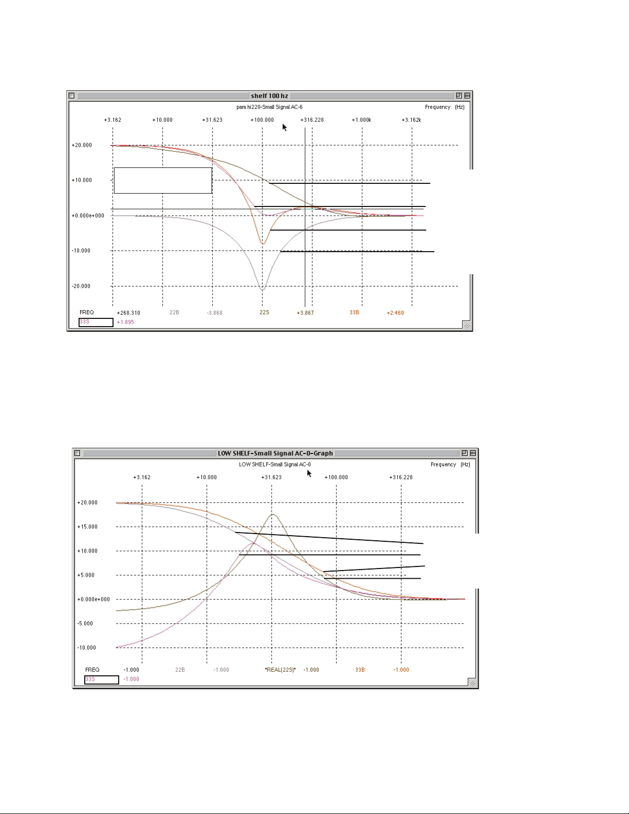
LOW SHELF CURVES
Just like most EQs, a 100Hz low shelf
doesn't reach "max" until about 10 Hz.
13
14

LOW SHELF +20 WIDE BW
LOW SHELF +20 MED BW
LOW SHELF -20 MED BW
LOW SHELF -20 WIDE BW
LOW SHELF +20 WIDE BW
LOW SHELF +20 NARROW BW
LOW SHELF -20 NARROW BW
LOW SHELF -20 WIDE BW
NOTICE THIS 8 dB BOOST AT 100 Hz
WHILE SHELF CUTTING 100 Hz
AND NOTICE THIS 8 dB DIP
WHILE SHELF BOOSTING
THE HALF WAY (10 dB) POINT
HAS SHIFTED TO 50 Hz
THESE CURVES SHOW ONE OF THE IDEOSYNCRACIES
AND IT IS POSSIBLE FOR A LF BOOST TO SOUND AS IF IT HAS LESS LOWS
DEPENDING ON THE FREQUENCY AND INSTRUMENT.
SIMILAR CURVES APPLY TO THE HIGH SHELVES AND
PARTICULARLY 10K AND 12K CAN BE STRANGE WHEN THE BW IS NARROW
THIS IS ABOUT +1.5 DB
AT 300 Hz AND NEGLIGIBLE
MORE 100Hz SHELVES SHOWING
BOOST AND CUT WITH VARIOUS BANDWIDTHS
14
50 100
SPICE SIMULATION CURVES
15

Narrow Bandwidth
Bandwidth at 12:00
Wide Bandwidth
Wide Bandwidth
Bandwidth at 12:00
Narrow Bandwidth
"dB" set at max (20 dB) and changing the Bandwidth
Max Boost Narrow Bandwidth
12:00 Boost Narrow Bandwidth
Max Boost Wide Bandwidth
12:00 Boost Wide Bandwidth
Changing "dB" and Changing Bandwidth
TYPICAL BELL CURVES
15
16

LOW PASS FILTERS
HIGH PASS FILTERS
1.5 dB bump on the 6K,
7.5K and 9K Filters
16
17

GAIN TRIM
+4 / -10 CHANGE
6414/12BH7
5751/12AX7
(12AU7 Mastering Ver.)
6414/12BH7
AC VOLT CHANGE
GAIN TRIM
+4 / -10 CHANGE
6414/12BH7 6414/12BH7
THE GUTS
1) To Open: Disconnect the AC Power cable, let sit 15 minutes to allow the power supply capacitors to discharge. Remem-
ber there are high voltages (300VDC) used in the Massive Passive and that the capacitors may continue to hold a charge
after power is removed - BE CAREFUL! We suggest using gloves and/or “one hand only” when the top is off.
Remove the single Philips Machine screw located on the top perforated panel (towards the back and center). Slide the
perforated panel towards the back.
2) Replacing Tubes: The tubes are marked as to their type 5751/12AX7 (for voltage gain; 12AU7 in the Mastering Ver-
sion) and 6414/12BH7 (for line drivers). Another warning: Tubes get HOT. Let them cool before you attempt to touch
them. Wiggle the tube back and forth as you pull it up. If you suspect a tube, you can swap it with the other channel. If the
problem follows the tube, you were right, it is that tube. If not, try swapping another pair of tubes. It is a good idea to have
a few spare tubes for emergencies as this will x better than 90% of most problems.
3) Changing AC MAINS VOLTAGE: Disconnect the AC Power cable. See on the diagram above the “AC VOLT
CHANGE”. Use a small at screwdriver set voltage change over switch to 120VAC or 240VAC operation. Replace main
Fuse with correct type and value. For fuse information refer to Pg. 29..
4) Changing the 1/4” phone jacks for -10dBv levels: The Massive Passive is factory wired for professional +4dBu
levels for both all of the XLR and 1/4” phone jacks. This procedure only changes the 1/4” jacks - not the XLRs. Do not
assume that “balanced” implies +4dBu levels or that “unbalanced” implies -10dBv consumer levels. Balanced only means
that there are 3 wires in the cable and that 2 of these wires carry signal in opposite phases and that the same impedances
(source especially) exist. Unbalanced refers to a cable system with two wires (signal and ground). “+4dBu” refers to pro-
fessional signal levels (0VU=1.228 volts AC into 600 ohms). “-10dBv” refers to consumer signal levels common to hi-
and low budget semi-pro gear and is typically 14 db lower than pro levels. The common connector is the RCA style phono
jack. 1/4” jacks are used for a wide variety of signal types and levels, including +4, -10, instrument Hi-Z and speakers and
headphones. 3 conductor plugs are used for balanced signals, inserts (send and return) and stereo (L&R) which tend to be
incompatible. Simply plugging in a 1/4” to 1/4” cable from one piece of gear to the next is not guaranteed to work. You
may have to check the operators manuals if you run into problems.
See the diagram above for the DIP SWITCH locations and the next page for a closer look.
18
5751/12AX7
(12AU7 Mastering Ver.)

+4 dBu
INPUT
OUTPUT
BACK PANEL
-10dBv
INPUT
OUTPUT
BACK PANEL
BACK PANEL
+4 dBu
INPUT
OUTPUT
BACK PANEL
-10dBv
INPUT
OUTPUT
Channel 1 Channel 2
LEFT CARD
DIP SWITCH SETTINGS
RIGHT CARD
This procedure also results in a polarity reverse which means that the 1/4” outputs will reverse phase both in bypass
and EQ. This may not be problem but you should be aware of this. It is denately better to keep PC or “polarity cor-
rect” in general. If it is a problem, you may be able to correct the polarity simply by hitting the “phase button” on the
corresponding channels on the console or re-wiring the input plug so that signal is on the ring and the tip and sleeve are
grounded via the shield. This procedure does not affect the XLR levels or polarity. Sorry, but all previous Manley Pro
Gear is only designed for +4dBu levels and this is the rst accomodation we have made for -10dBv. We really only did
it this time because it was easy in this circuit (it was an after-thought) and not intended in the basic design. We suggest
using the XLRs rst, the 1/4” at +4 levels second and only doing this procedure for -10 levels, if you really must.
Here are the DIP SWITCHES. There are two switches on each little package or pair and two packages or pairs on
each card and two cards (channel one and channel two). The two switches should always be opposite - one ON and one
OFF. UP is ON. When (TOP PAIRS) the switches closest to the front panel are UP and ON and (BOTTOM PAIRS) the
switches closest to the front panel are DOWN and OFF the 1/4” jacks are set up for +4 dBu levels.When (TOP PAIRS)
the switches closest to the front panel are DOWN and OFF and (BOTTOM PAIRS) the switches closest to the front
panel are UP and ON the 1/4” jacks are set up for -10dBv levels. The latter increases the input gain and decreases the
output level. The pair of switches closest to the top of the card set the input gain and the pair closest to the bottom set the
output levels. On these output switches, if both are OFF then you lose output to the 1/4” jack. If both are ON important
parts of the circuit will be shorted together and the unit will oscillate.
5) Removing individual EQ cards: You have to remove the top perforated panel rst. Each card has a short ribbon ca-
ble from the toggle switch board to the EQ card. You have to pull the ribbon connector from the EQ card before you pull
out the card. Once the ribbon is free at the EQ card end, unscrew the two allen keys holding the oblong black anodized
panel. Gently pull the card towards you, being sure the ribbon cable is not catching on any of the EQ card components.
To return an EQ card into its slot, do the procedure in reverse. The only difference is that you need to watch the back of
the card and align the 14 pins into the connector and not offset.
Considering there are no active components on these EQ cards it is unlikely they will need to be repaired or removed.
There are a few minor differences between the 4 EQ cards and you should not change the order. These differences
involve the “voicing” to the 22Hz, 33Hz, 16K and 27K shelves.
19

Equalizers
EQs range from simple bass and treble controls on a hi system to
pretty tricky parametric EQs and 1/3 octave graphic EQs. As an audio
freak, you have probably tried quite a few EQs and have gotten both
great results and sometimes less than great and you probably have a
favorite EQ. Now that you probably have a digital system, you may
have questions about these digital EQs and the differences between any
analog and digital techniques. Let us begin at the beginning, and then
get into some real techniques. Who invented the rst electronic tone
control? Who knows? The rst hints of “at” electronics came decades
later. Simple bell and shelf EQs seem to have been born in the 1930’s
for telephone company use. The Pultec passive circuits came from that
era at Western Electric. “Graphic EQs” seem to have been invented
in the mid 60’s and were common by the early 70’s. A 19 year old
prodigy, George Massenburg rst described, in a 1971 AES paper, the
“Parametric Equalizer”.
All EQs do one thing — they can make some bands or areas of
frequencies louder or quieter than others, manipulating the frequency
response. Speakers and mics do that to but we normally think of EQs
as something that allow us to alter the frequency response, deliberately,
with some knobs and buttons - including the GUI ones. Some equaliz-
ers have no controls, they are part of a circuit and generally are almost
“invisible” to the user. A good example of this is the EQ circuits used as
“pre-emphasis” and “de-emphasis” used for analog tape machines and
radio broadcasting. The idea of these is to boost the high frequencies
before it hits the tape (or air), then reduce the highs on playback (or
reception). This reduces the hiss and noise and usually allows a hotter
signal which also improves the noise performance. These EQs usually
have trimmers available but we would rarely consider using them for
adjusting the tone. Instead, the object is to get a ruler-at response at
this part of the signal chain. It is still called an equalizer. In fact the
original denition of “equalizer” was a device to restore all the frequen-
cies to be equal again, in other words, force the frequency response to
be as at as possible.
Other common EQs that you are probably familiar with include the
common 1/3 octave graphic EQs with about 30 or 60 cheap sliders
across the front panel. These are usually a good tool for tuning a room,
but they may be a difcult thing to use for individual sounds. Most
1/3 oct EQs excel when a number of little tweaks spaced across the
spectrum are needed but not great for wide tonal changes. Too many
resonances. Some room tune experts are now relying on parametrics
with continuously variable frequency knobs apparently to “nail” the
peaks. One reason 1/3 octave EQs have a bad name are the “real time
analyzers” that display a single aspect of the frequency response but
without any time information, real or otherwise. People often get much
better results with warble tones, or tuning rooms by ear with music. 1/3
octave EQs are appropriate for some mastering tasks but are probably
less used because they tend to scare clients. The Massive Passive was
not intended for room tuning. Perhaps a future version with active con-
stant Q mid bands in combination with a good 1/3 octave EQ may be a
very nice thing for that tricky job.
Parametric EQs come in lots of avours, 3, 4 or 5 bands, most with 3
knobs per band and lots of variations. The earliest ones offered only
bell shapes, no shelves, no lters. Today’s most common variation has
2 mid bells with Q, a high shelf, low shelf and lters. We see these in
many consoles and in outboard EQs at a wide range of prices. Almost
all have limitations either in boost/cut range, Q range, frequency range
or overlap and audio performance.
Now we have a new breed of digital parametrics that have few
limitations - other than does it actually sound good and is it avail-
able for your format and is it stable and bug-free and is it a hassle
to get a signal in and out of it? Within their realm, some are getting
good.
Passive EQs have come out over the the 60 (150) odd years for a
variety of different purposes. If we include all inductor/capacitor
based EQs the list includes API 560’s, most of Rupert’s designs
up to the 80’s, all the Pultecs and Pultec clones and a number of
high end 1/3 octave graphics. Essentially the list includes most of
the desirable vintage EQs that comprise many engineer’s all-time
favorites. The Massive Passive is one of the only non-clone tube
passive EQs and the only one we know of that is 4 band quasi-par-
ametric with boost and cut on each band. There ain’t nothin’ like it.
Now there are a large number of enhancers, exciters, extenders and
multi-band compressors, that usually use combination of EQ, dis-
tortion, dynamic effects and deliberate phase shift to create effects
that are related to EQ. They all seem to come with a warning “not
to overuse”. The more “secretive” it is the more we should hold it
suspect. Some of these are boxes are useful and often a reasonable
alternative to conventional EQs. Sometimes, we think “if my EQs
and Limiters did what I wanted, then I sure wouldn’t use this”. We
hope that the Massivo helps towards this quest. If you like what
the magic boxes do, use them, but carefully because the results are
rarely reversible.
What most EQ’s have in common is in the shapes of the shelves.
Almost all shelves can be designated as “rst order” which means
that a single capacitor (or inductor) is used to shape the frequency
response. Second order implies two components, etc. A rst order
lter is generally 6 dB/oct, second order should be 12 dB/oct,
third order 18, etc. Shelf EQs never quite get to 6 dB/oct and at
the steepest point seem to be 4.5 dB/oct which is pretty gentle and
why a 10K boost seems to affect mids. Bell curves are normally
second order but arranged to create a damped resonance. On a rst
order shelf, the capacitor may be surrounded by any number of
components to create gain or to simulate an inductor or for other
purposes. These other components are a large reason why different
EQs sound different, but that single capacitor sets up a frequency
response curve that is very similar for almost all EQs. The shelves
on the Massive Passive combine a rst order shelf with a variable
depth second order bell. At wide bandwidths it acts rst order and
at narrow bandwidths approaches third order. We have played with
true second and third order shelves with real 12 and 18 dB/oct
slopes and they sound pretty damn good. When you boost or cut a
band of frequencies, with a steeper slope, you affect the frequen-
cies that you are aiming for, with much less action on other fre-
quencies that you didn’t intend to touch. Of course, to build an EQ
like this with frequency selection (even more need) the component
cost and complexity rises fast.
The future of EQs may bring us bells where each side (high & low)
plus the top “atness” can be adjusted separately. We are begin-
ning to see variations of shelves in plug-ins but so far it is just Tom
copying Dick who mimmicked an analog circuit by Harry. Perhaps
another parameter would be nice like, a sepately adjustable phase
shift or distortion. And if we could bend the rules of nature and
have a non-resonant bell with zero ringing, we might have some-
thing truly new to hear. It would be very transparent but probably
quite un-natural sounding. There is validy to “physical modelling”
even in analog EQ circuits. “Natural” is kinda nice and very easy to
listen to.
20
Table of contents
Other Manley Stereo Equalizer manuals


Popular Stereo Equalizer manuals by other brands

IMG STAGE LINE
IMG STAGE LINE MEQ-115/SW instruction manual

SABINE
SABINE GRAPHI-Q2 operating guide

Iron Age Audioworks
Iron Age Audioworks V2 user manual

Klark Teknik
Klark Teknik DN410 user manual

Chandler Limited
Chandler Limited Little Devil Equalizer Controls and features

Peavey
Peavey CEQ 28R operating instructions


