Manrose FAN6882 User manual
3. External Grille
Locate the position for the external grille and cut a
130mm diameter hole. Connect one end of the
125mm diameter duct to the spigot of the external
grille.
Note: Since the length of each duct is 3.0m, make
sure the centre of the installation hole is no more
than 3.0m from the vent.
Note: In order to get an effective ventilation, it is
suggested that the duct is no more than 3.0m in
length.
Caution: Use appropriate safety PPE when cutting
fibre cement products.
4. Wiring
Connect one end of the interconnecting wire to the wall switch panel, and bring the other end
out of the hole in the ceiling. Open the terminal block cover on the unit’s housing, make the
connection as per the wiring diagram instruction below, then reposition the terminal block
cover. Press excess wire back into the ceiling.
Note: Ensure that the power is isolated before carrying out any work on electrical installations.
5. Fit the tie-in into the fan outlet in the housing with
Ø125mm duct clip. Fit the in-house end of the duct to
the fan outlet, and fix the end with duct tap.
Note: Keep the route as straight as possible.
6. Position the housing into the hole
Insert the unit into the square hole being sure to pull the
side clips inward so that the body can pass through the
hole without damaging the plaster. Rotate the swing
clips to hold motor body in place then tighten screw to
let the clip clamp onto the ceiling board.
7. Final Installation
1. Reconnect the LED downlight.
2. Replace the Fascia
Replace the fascia and retaining springs.
3. Replace the Lamps
Ensure the lamps are tightened sufficiently to make
good electrical contact. Clean the lamps and fascia.
4. Fix the Switch Panel to the Wall
Fit the switch panel onto the wall, ensuring that in
this position it is not subjected to splashed water.
Note: The switch wiring should be routed inside the
wall. If it is necessary to run the wiring on the outside
of the wall, use a suitable conduit and fixings to
properly locate and hold the wiring used.
INSTALLATION INSTRUCTIONS AND HOLE-CUTTING TEMPLATE
Read and save these instructions! Please take this card as hole cutting template 320mm x 320mm
SATIN
FAN6882/FAN6883
Dear customer,
Thank you for selecting MANROSE. Please read all instructions before commencing installation.
WARNING - ALL WIRING MUST BE CARRIED OUT BY A REGISTERED ELECTRICIAN
1. Use this SATIN heat-fan-light unit only as described in this manual. Any other use not
recommended by the manufacturer may cause fire, electric shock, or injury to persons.
If you have questions, contact the manufacturer or local agent.
2. All wiring must be carried out by a Licensed Electrician in accordance with all national wiring
codes.
3. Make sure the power is isolated before installing.
4. When cutting into the ceiling, do not damage electrical wiring and other hidden utilities.
5. The SATIN heat-fan-light unit must be properly earthed.
6. The lamps are hot when in use. Do not touch the infrared lamps when in use.
7. Precautions must be taken to avoid the back-flow of gases into the room from the open flue of
gas or other open-fire appliances when mounted in outside walls or soffits.
8. The SATIN heat-fan-light unit must be isolated from the power by means of a plug or a switch
capable of disconnecting all poles with a contact separation of at least 3mm in each pole.
9. The power cable must be rated for a minimum 10A inductive load.
10. The appliance is not intended for use by persons (including children) with reduced physical,
sensory or mental capabilities, or lack of experience and knowledge, unless they have been given
supervision or instruction concerning use of the appliance by a person responsible for their safety.
11. Children should be supervised to ensure that they do not play with the appliance.
IMPORTANT CONSIDERATIONS BEFORE INSTALLING
A few minutes of planning can make a big difference to the installation time and ultimate
satisfaction with the functioning of the unit.
1. The unit should not be installed directly above a shower or bathtub. The unit must not be
installed in a position where water may splash onto the lamps.
2. The unit must not be installed beneath a fixed electrical socket.
3. The unit is designed for installation in flat ceilings only. Do not mount it on a sloping ceiling or a
vertical wall.
4. The infrared lamps are most effective when you are standing directly beneath them, so generally
the unit would be mounted above a place where you would stand to dry yourself.
5. For the exhaust fan to work efficiently, replacement air of a volume equivalent to what is being
extracted must be able to enter the room. Generally this air would be drawn under the door.
If the room is airtight, the fan will not exhaust air efficiently.
6. Before commencing any cutting, check in the ceiling space that there are no obstructions such
as ceiling joists and that there is sufficient height clearance for the housing. Check that the
electrical wiring can be routed from the wall switches to the mounting location.
INSTALLATION
1. Locating the SATIN Heat-Fan-Light unit
For the purpose of obtaining the best heating effect from the lamps there should be at least
2.3m overall height from unit to ground.
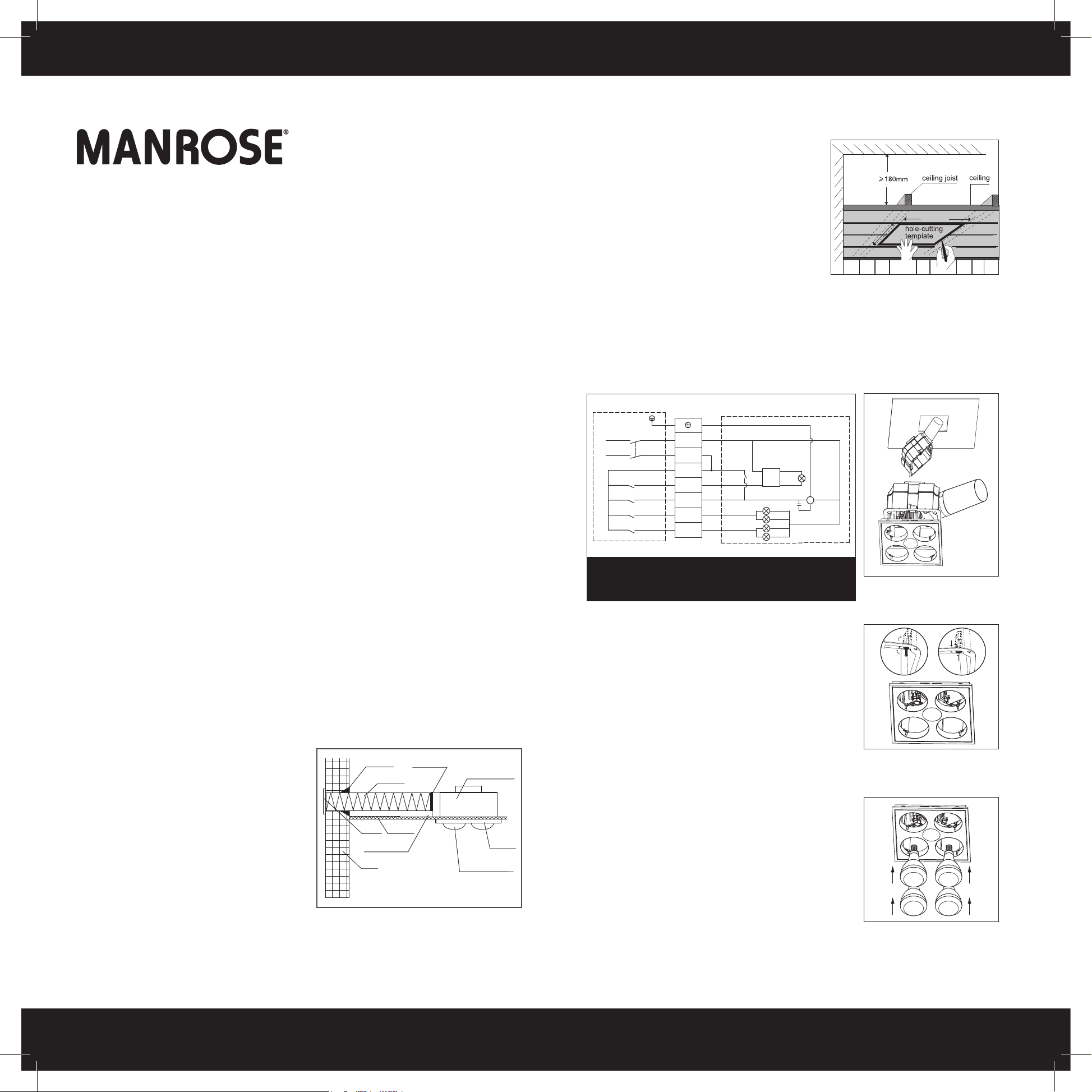
2. Prepare the ceiling
Select the mounting position for the unit.
Check that it is possible to route the ducting
from the unit to the outside of the house.
This will generally be to the soffit but can be
to a wall outlet location (as pictured).
Use this hole-cutting template to mark the
hole on the ceiling. Make sure a distance
between the edges of the unit and wall is
no less than 250mm. There should be a
minimum 220mm vertical distance between
the ceiling and roof.
sealant
grille
heat-fan-light
duct
infrared lamps
wall
ceiling
fascia
ceiling joist
duct clip
320mm
320mm
N
L
LIGHT
FAN
HEAT
HEAT
LED power
driver
thermostat
N
L
K4
K3
K2
K1
~
M
C
Motor
heat lamp
L
WARNING
Failure to connect a permanent live connection to the
Heat-Fan-Light will result in failure of critical safety features

INSTALLATION INSTRUCTIONS AND HOLE-CUTTING TEMPLATE
Please take this card as hole cutting template 320mm x 320mmRead and save these instructions!
USE
Our bathroom SATIN heat-fan-light unit uses the infrared heating lamps as a source of heat.
It also combines the functions of exhaust and light.
1. Heat
'HEAT' button On/Off
This model is supplied with two groups of infrared heat lamps. You can switch them on
in banks of two for an optimal heating effect. Each individual infrared lamp has been
sprayed with 4ºC cold water to ensure that there are no flaws in the construction.
Note: Do not touch the infrared lamps with any part of your body when in use.
2. Exhaust
'FAN' button On/Off
This unit can exhaust odours and steam in a quick and efficient way by turning on the
"FAN" button.
3. Lighting
'Light' button On/Off
Note: Do not switch on/off frequently when in use. Turn the power off if not in use over a
long period.
MAINTENANCE
1. Clean
1. Shut off the power before cleaning.
2. Wipe lamps and fascia with care using a soft cloth soaked with a neutral detergent.
Note: Ensure the lamps are cool to touch before handling.
2. Lamp Replacement
1. Check and tighten lamps regularly.
2. Shut off power before replacement.
3. Use 10W max. LED downlight ø80mm x 40mm for lighting.
4. Use E27 275W infrared lamps for heating.
Note: It may affect operation (even cause danger) if lamps other than the designated
ones are used.
WARRANTY - 5 YEARS / INFRARED LAMP - 2 YEARS
The main unit and fan motor is warranted against factory fault for a period of 5 years and
the oiriginal supplied MANROSE infrared lamps for a period of 2 years. Labour costs are
not covered. Please keep and bring the original invoice to your place of purchase for
warranty services.
This warranty does not cover damage or loss caused by:
1. LED lamp or failure of LED lamp.
2. Any consequential losses arising from incorrect installation or operation or
maintenance of this product.
3. Any consequential losses arising from incorrect wiring of this product.
4. Any consequential losses arising from repairing of any part of this product by
unauthorised persons.
Fill out the following details and file with the purchase invoice for warranty service.
MANROSE SATIN
MODEL NO. FAN6882/FAN6883
Purchased from:
Date of purchase:
Note: Instructions and specifications are subject to change without notice.
MAIN TECHNICAL PARAMETERS
Model Numbers FAN6882/FAN6883
Rated Voltage 220-240V AC
Rated Frequency 50Hz
Rated Power 1080W-1180W
LIST OF ACCESSORIES
Operation Unit 1 piece
Infrared Lamp (E27) 4 pieces
LED Lamp 1 piece
Installation Instruction & Hole-cutting Template 1 piece
3.0 metres Flexible Ducting 1 piece
Grille 1 piece
Duct Clip 1 piece
Switch 1 piece
This manual suits for next models
1
Other Manrose Electric Heater manuals

Popular Electric Heater manuals by other brands

Bigassfans
Bigassfans OBSIDIAN BAFC30240B Installation, operation and maintenance manual

Kingfisher
Kingfisher BUFRUK manual

DeLonghi
DeLonghi ELECTRIC CONVECTOR HEATER Instructions for use

Dimplex
Dimplex TRFB 150 Mounting and operating instructions

Chromalox
Chromalox PF495-1 Installation, operation and renewal parts identification

DeLonghi
DeLonghi HVR 9033 Retr instructions

Harvia
Harvia TRT90 Instructions for installation and use

Sanotechnik
Sanotechnik B100 Installation

Greenheck
Greenheck ERH-20 Installation, operation and maintenance manual

Dryfast
Dryfast DEH5 instruction manual

Rointe
Rointe ecodesign ZOCCA OVAL Installation and user manual

Adam
Adam Solaris Use & care manual


