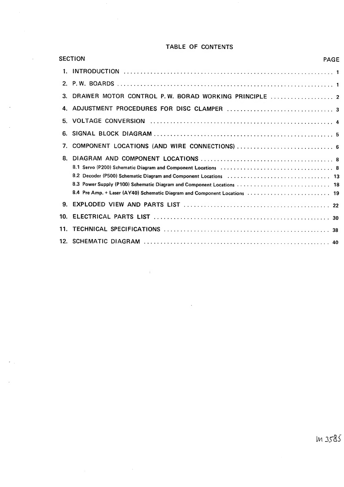
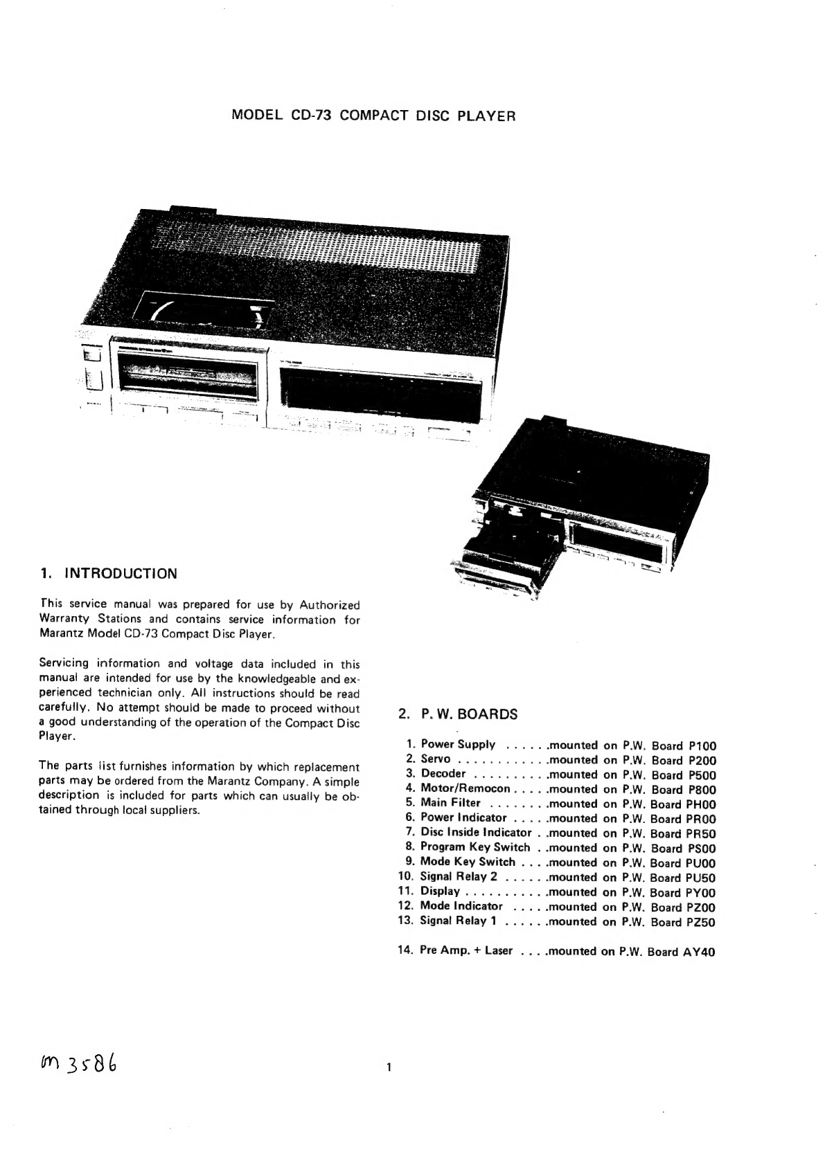
Marantz CD-73 User manual

wwa.
CD-73
VA
7
PYNs
ERR
eR
BPacn
ERE
ZZ’
model
CD-73

TABLE
OF
CONTENTS
SECTION
PAGE
Re
EN
TRODUGTIONS
Sosiuteucie
cana
hank
hws
Hered
eeu
vas
ew
aca
Sanh
Galatea
laatee
Seeded
ees
1
ae
Pee
BORROS
2.
te
tie
Serene
ehtete
bu
ON
Vein’
ea
ae
ear
mehate
ula
Ae
len
euhae
ag
1
3.
DRAWER
MOTOR
CONTROL
P.W.
BORAD
WORKING
PRINCIPLE
...................
2
4.
ADJUSTMENT
PROCEDURES
FOR
DISC
CLAMPER
................
0.0.00
ccs
eeeuuee
3
5:
VOLTAGE
CONVERSION:
sensi
eetaceans
a
a
aine
oe
pen
ee
ee
a
Matas
4
6:
SIGNAL,
BLOCK:
DIAGRAM
202
<5ccu
5s
cel
Sie
ee
tales
dea
ta
tka ban
aee
et
aren
oa
iene
5
7.
COMPONENT
LOCATIONS
(AND
WIRE
CONNECTIONS)
...................0.00.-0000
6
8.
DIAGRAM
AND
COMPONENT
LOCATIONS
..............
0.0.0:
c
cece
cece
e
eee
e
ees
8
8.1
Servo
(P200)
Schematic
Diagram
and
Component
Locations
............
20000
e
eee
eee
eee
eens
8
8.2
Decoder
(P500)
Schematic
Diagram
and
Component
Locations
....
2.0.0.0.
c
eee
eens
13
8.3
Power
Supply
(P100)
Schematic
Diagram
and
Component
Locations
..........-
0-0.
e
eee
eee
eee
ees
18
8.4 Pre
Amp.
+
Laser
(AY40)
Schematic
Diagram
and
Component
Locations
......-.
0.0000
cece
eeee
eae
19
9\-
EXPLODED
‘VIEW
AND:
PARTS
LIST
b:54.c00
9-5
e250.00
055
Ges
w
SEES
eed
heeled
22
10.
ELECTRICAL<PARYTS
LISP
sche
thutrwd
seein
de
Poses
eee
Seen
eae
4
tet
eal
30
11.
“TECHNICAL.
SPECIFICATIONS
\3
<4.
oxc0
2
5
2cad
e
ceawet
shinee
d
bale
ees
ae
aoe
ile
bea
es
38
12;
“SGHEMATIC
DIAGRAM
.4o053-.t¢cdc0sedindn
sds ety
oto
hess
ad
Sokelew
teins.
40
Im
3585

MODEL
CD-73
COMPACT
DISC
PLAYER
1.
INTRODUCTION
This
service
manual
was
prepared
for
use
by
Authorized
Warranty
Stations
and
contains
service
information
for
Marantz
Model
CD-73
Compact
Disc
Player.
Servicing
information
and
voltage
data
included
in
this
manual
are
intended
for
use
by
the
knowledgeable
and
ex-
perienced
technician
only.
All
instructions
should
be
read
carefully.
No
attempt
should
be
made
to
proceed
without
a
good
understanding
of
the
operation
of
the
Compact
Disc
Player.
The
parts
list
furnishes
information
by
which
replacement
parts
may
be
ordered
from
the
Marantz
Company.
A
simple
description
is
included
for
parts
which
can
usually
be
ob-
tained
through
local
suppliers.
Mm
3586
2.
P.W.
BOARDS
.
Power
Supply
.
Servo
.
Disc
Inside
Indicator
.
.
Program
Key
Switch
.
.
.
Mode
Key
Switch
...
.
.
Signal
Relay
2
.
Display
...........
.
Mode
Indicator
.
Signal
Relay
1
WON
AKHAWNS
=
Ey
s
n
a
o
g
=
oO
—
a
N
=a
—
w
=
po
.
Pre
Amp.
+
Laser
...
mounted
on
P.W.
mounted
on
P.W.
mounted
on
P.W.
mounted
on
P.W.
mounted
on
P.W.
mounted
on
P.W.
«mounted
on
P.W.
mounted
on
P.W.
mounted
on
P.W.
mounted
on
P.W.
mounted
on
P.W.
mounted
on
P.W.
mounted
on
P.W.
-mounted
on
P.W.
Board
P100
Board
P200
Board
P500
Board
P800
Board
PHOO
Board
PROO
Board
PR50
Board
PSOO
Board
PUOO
Board
PU50
Board
PYOO
Board
PZ00
Board
PZ50
Board
AY40

3.
DRAWER
MOTOR
CONTROL
P.W.
BORAD
WORKING
PRINCIPLE
Drawer
motor
control
P.
W.
Borad
includes
the
following.
(1)
Drawer
motor
drive
circuit
(2)
Remote
control
circuit
(Marantz
Bus
System
decoder
circuit)
3.1
Drawer
Motor
Drive
Circuit
A.
Outline
of
the
system
This
circuit
revolves
and
reverses
the
drawer
motor
by
the
OPEN/CLOSE
switch
of
S802
on
the
front
panel
to
open
and
close
the
drawer.
It
includes
a
circuit
to
increase
starting
torque
and
a
safety
circuit
which
stops
automatically
when
something
is
caught
in
the
drawer.
B.
Operation
of
each
part
a)
Q809,
Q808
and
Q807
are
motor
drive
circuits.
Especially
Q808
increases
motor
starting
torque.
b)
When
the
voltage
of
R820
becomes
over
about
0.6V,
the
base
current
begins
to
flow
through
Q803.
That
is,
the
motor
is
locked
to
detect
the
excessive
current.
c)
Q805
and
Q806
make
up
a
set/reset
flip
flop,
which
is
set
whell
positive
voltage
is
put
into
the
base
of
Q805.
And
it is
reset
when
the
base
becomes
0.
As
long
as
it is
set,
D806
is
‘ON’
and
motor
drive
circuit
does
not
operate.
d)
Q802
becomes
“ON’’
just
for--a
few
msec
when
the
OPEN/CLOSE
switch
of
S802
is
pushed.
(S802
is
non-shorting
type.)
OPENSCLOSE
Vv
|
\
!
e)
Q801
becomes
“ON’’
just
for
the
time-constant
t4
based
on
R816/R801/C801only
afterS802
is
changed
from
CLOSE
to
OPEN,
and
makes
the
base
of
Q809
OV
to
stop
the
motor
drive
circuit.
Meanwhile,
the
voltage
of
C807
is
discharged
to
increase
the
torque
for
the
time-constant
t
of
C807/
R822
just
after
the
end
of
ty.
.
Explanation
of
overall
operation
a)
During
the
shift
of
OPEN/CLOSE
switch
S802,
from
OPEN
to
CLOSE,
Q802
becomes
“ON”
in
an
instant
and
flip
flop
which
is
composed
of
Q805
and
Q806
is
reset
to
cut
off
D806.
b)
Consequently
motor
drive
circuit
which
is
composed
of
Q809,
Q808
and
O807
begins
to
operate
to
switch
on
the
drawer
motor.
c)
When
the
drawer
comes
to
the
mechanical
end,
short-circuit
current
begins
to
flow
to
the
motor
to
generate
voltage
of
R820
about
1V.
This
voltage
reverses
Q803
to
cut
off
D804.
After
D804
is
cut
off,
C805
is
discharged
through
R807
and
Q804,
and
Q804
becomes
OFF
after
about
2.5
sec.
As
a
result,
the
collector
voltage
of
Q804
rises
to
set
the
above
flip
flop
through
R809/R810.
In
this
way,
the
motor
drive
circuit
becomes
OFF
again.
f)
You
have
the
same
operation
also
when
S802
is
changed
from
CLOSE
to
OPEN.
But
Q801
has
been
added
so
that
Q808
which
increases
start
up
torque
can
become
ON
without
fail.
d
e
CLOSE>OPEN
Vv
t
|
|
!
|
Q802
Collector
|
|
if
| |
Sf
Motor
Current
I
!
}
|
|
(\
|
I
|
|
R820
Voltage
ae
CLOSE
Joo
nm
a
Position
DRAWER
Position
OPEN
Position
!
|
|
i
|
}
I
|
|
!
I
|

3.2
Remote
Control
Circuit
A.
Outline
of
the
system
Marantz
Bus
System
is
a
general
term
to
this
remote
contro!
circuit.
Remocon
transmitter
and
remocon
receiver
are
necessary
to
operate
it.
The
output
of
the
remocon
receiver
is
connected
to
the
remocon
“IN”
terminal
on
the
rear
panel
of
the
CD-73.
The
remocon
transmitter
has
4
keys
for
play/next,
puase,
repeat
and
stop.
B.
Operation
of
each
part
a)
Q851
is
N
channel
Micro
Processer
for
remocon.
b)
Q857
amplifies
a
signal
from
the
remocon
receiver
and
transmits
it
to
pin
24
of
the
Micro
Processer.
c)
O858
is
a
transistor
switch.
When
a
laser
signal
‘“S”
becomes
Low
level,
it
switches
‘“‘ON’’
and
changes
the
Micro
Processer
pin
25
to
High
level
to
generate
an
easy
operation
signal
at
pin
19.
This
easy
operation
signal
is
reversed
at
Q856
and
put
out
from
the
easy
“OUT”
terminal
of
the
CD-73.
This
signal
makes
easy
operation
possible.
Q853,
Q854
and
Q855
are
used
as
analogue
switches
and
controled
by
output
pin
9,
10
and
15
respective-
ly.
Q852
is
a
transistor
switch,
which
lowers
a
sense
signal
to
GND
level
to
stop
operation.
R852/D851/C856
are
used
for
initial
setting
of
the
Micro
Processer.
d
—
—
e
C.
Overall
operation
When
any
key
of
the
remocon
transmitter
is
pushed,
a
pulse
signal
is
transmitted
to
the
CD-73
remote
“IN”
terminal
through
the
remocon
receiver.
This
signal
is
put
into
the
Micro
Processer
pin
24
after
being
amplified
at
Q857
and
the
Micro
Processer
comes
to
correspond
to
the
key
to
generate
High
signal
at
the
output
pin
as
follows.
play/next
........
ping
pause
...........
pin
10
repeat...
.........
pin
15
STOP
s(inane
eae
4d
pin4
Besides,
only
when
the
play/next
key
is
pushed,
an
easy
Operation
signal
occurs
at
pin
19
for
60
msec
to
mute
the
other
sources.
m
3588
4.
ADJUSTMENT
PROCEDURES
FOR
DISC
CLAMPER
4.1
Adjusting
the
height
of
the
pressure
ring
holder
The
height
of
the
holder
must
be
adjusted
to
maintain
braking
by
keeping
the
appropriate
distance
between
the
holder
and
pressure
ring.
With
the
drawer
in
the
unit,
lift
the
holder
manually,
and
place
the
positioning
tool
on
the
turntable.
If
the
drawer
is
in
the
“out”
position,
the
alminum
cap
will
come
in
contact
with
the
front
chassis
and
front
panel,
and
will
be
scratched
when
the
drawer
is
pushed
into
the
unit.
With
a
screwdriver,
turn
the
adjustment
screw
clockwise
2
or
3
turns.
Push
down
the
holder
several
times
to
confirm
that
it
sinks
a
few
milimeters
until
it
makes
contact
with
the
positioning
tool.
If
there
is
no
play
between
the
holder
and
tool,
turn
the
adjustment
screw
further
until
a
few
milimeters
play
is
obtained.
Turn
the
adjustment
screw
counterclockwise
until
the
play
between
the
holder
and
tool
becomes
zero.
For
optimum
adjustment,
do
not
exert
excess
pressure
on
the
acdiustment
screw
with
the
screwdriver.
Apply
lock
paint
to
the
adjustment
screw.
Lift-the
holder
with
the
drawer
in
the
“in”
position,
and
remove
the
positioning
tool.

5.
VOLTAGE
CONVERSION
@
EUROPEAN
MODEL
ONLY
To
convert
the
unit
to
a
different
power
source
voltage,
change
the
position
as
illustrated
in
the
drawing
below.
CAUTION
DISCONNECT
POWER
SUPPLY
CORD
FROM
AC
OUTLET
BEFORE
CONVERTING
VOLTAGE.
Voltage
Conversion
Chart
240V
~
120V
~
220V
~
Hi0V
~
VOLTAGE
SELECTOR
Note
on
safety:
Symbol
/\
Fire
or
electrical
shock
hazard.
Only
orignal
parts
|
should
be
used
to
replace
any
part
marked
with
symbol
“\
.
|
Any
other
component
substitution
(other
than
original
|
type),
may
increase
risk
of
fire
or
electrical
shock
hazard.
F
m
35.84

6.
SIGNAL
BLOCK
DIAGRAM
gagiz6z
AQddNS
are
rent
AIO
220.
and)
Vay
Onan,
osx}
40
One
1x
QHVORAIy
Md
Vy
Fy
a
OAW3S
AV1dS10
ees
+H3A1H0
“on
894
2x19
PpH
20
191.0
2720 1020
1
Oe
"5020
I20
310W
Sey
oe
Van
oo
401031
30%0VEL
SE
Liz
OYLNOD
135430
O89
*S120,
eH
2
yO
ero
px
g4
H(2i-L)
21
520
ed
O
In2o
Oa
p
Zee
es
i
(eo
YOLOW
6020
STEVINYNL
sao
Wee)
BZEM
RZY
0520)
18Ze4
GPZO
POMPEZO
PT
NZIZO
TOHLNOD
NIVO
OLLVWO
LAY
+
1920
ove0
'D>
proeene
4
'
1
1
J
20
H
0
W
'
%
;
D
i
¥YOLO!
1
{
snoodt
SNOO4
OAYAS
:
3
reSY
C65u
20991099
W3
"3ud
80SY
10Su
feses=4
ae
wOuNs
SNI0s
1.
RY
'
1
Ke
’
AWLBWNAS
Va
(238
136)
21
YOUH3
OVE
pesseeat
‘
4
H
1
H
yo
1
43Sv1}
rr
|
=
st
s2s0.
6850
gs.
THI?
310
{oo
4
.
aso
Sy
2sy
4959
9959,
W3
“Aud
“a

7.
COMPONENT
LOCATIONS
(AND
WIRE
CONNECTIONS)
YE
REMOTE
JACK
CO
OUT
JACK
DECODER
PW.
BGARD
(P500)
Nee
|
“nem
fi
:
bbe)
Se
PRE
AMP
+LASER
CE
‘a
ASSY
(/
em
¢
:
(AY40)
me
|
ae
ii
‘
e
At
yo
.
S
£07
sh
‘
?
x
—
es
p
Co»
.
5
¥
, j
:
a
ay
ms
:
1
aril
oi
ne
ie
ane:
ein
,
i
12
tak
eee
‘
Ww
a
i
~
’
mis
=.
(3
Sa
|
‘
aig
i‘
it
wu
F
°
Pon!
ha
y
ps
Ss
alg.
ellis
4
:
cyl
Ue
eA
eR
—O
Cr
6
;
yet
fay
kana
2a
0
0
|
‘ve
‘
Ss
igs
TER
ee
a
——
|
peng
.
r;
¥-
C
WHT
—
we)
RE!
eee}
2)
tte
28
38
=
pear}
SERVO
PW.
BOARD
ee,
ei
pcomesey
(P200)
ee
POWER
TRANSFORMER
BLK
HT
DRAWER
FUSE
MOTOR
FOO!
yoo!
&
\,
REO
®@
@|
a
Pe
et
ise
eles
ae
4
sie
>
EEF
VoL
tase
3)
SELECTOR
Jog!
For(N,T,A)
VERSION
Bw
~
&
LK
POWER
P.W.
BOARD
(P100)
wa
vool
wool
AC
CORD
PHOQ
J
aS
|
if
ef.
i
H
oO
¥
1
Ed
i
N
HO2
For(N)
To
J801
To
TRANS.
AC
INLET
|
FUSE
atx
FOO!
yoo!
To
vs02
<=

8.
DIAGRAM
AND
COMPONENT
LOCATIONS
8.1
Servo
(P200)
Schematic
Diagram
and
Component
Locations
RADIAL
ERROR
|
A274]
C274
(A174)
.
SERVO
P.W.
BOARD
(P200
1/2)
getatvayic)
+2
on
(0474)
a
a2i2(1/4)(8)
#d
LM324
}
C250
ite)
oa
|
'
'
+
fr
O.2Vj
aeiativana)
SD
o2ie
4
i
MATAIIT
‘4
84
4
S4E
casi]
agai
aay
d
+
(Arn)
7
—a2i3i1/4xc)
HEF4070B
+s
0213
(1/410)
VY
|R365
-1
HEF40708
oat
244
9.4E
Cy
Eas.
c287
FITéy
ty
1000n}
RADIAL
:
WIR3E2
MOTOR
|
er
.
a
C233
a
v
‘
R386
aon
(e33K
C2324
232°
_
(4132)
R291
srs
-!
H
a2iaa/4na)
€
R300
LM324
[tLovl
R302
|,
=
2.2k)

SERVO
P.W.
BOARD
(P200
2/2)
Ri
8
R230
[470K]
BPR
ALA
alze)
R240
'
c2i1
100n
+1
FOCUS
R222
Tizk)
Cp
MOTOR
.
R220
+1
Eos
(S
231
VY
Asis
(#22k]
0208(1/2KB)
eos
|
FOCUS
,
°
ey
MC1458
8
é
ERROR
14
ca7i
(_2.2k)
5
ir
OV
R223
Ov
6
€0.9)
(AI71)
wap
ee
0
[>
[100]
[100k]
Ee
7
C22t
|
azzi
+1
+l
+l
+
&
c
P1008
Fa
4
+
caran
27n
+
a
208.172}
es
fom
|
MCl4
(~
:
Real
Q232
3R201
202
|
eat
|C201
‘3
E
E
ie
CK
/
80136
R203
ri
e
208
|
(A525)
MCES
>A3254,
C32
+2
MCES
|
a
(4524)
MuTE
>43244,6324
MUTE
+2
(A523)
P-BIT
>A32Z3h,
|
a
P-BIT
a
QR
Efe
(A522)
DO
|
-3A322
Bs
rf
62
Q20701/3XC)
C27Tay
A272
L
(AI7T2)
HEF4025
(asen
HEL
5
A32N
C32!
bie
S530
p
zeal
HFL
(A782)
SENSE
b
en
as
H
wag
Cee?
’
P
V7
170
PORT
|
taven
L
>A2el}cze!
|
|
\
£294}
A294
OLEN
(A794)
:
+2
sat
|c203
Aail
'
oh
T™M
(ASI)
Q207(1/3KA)
I
0207(1/318)
HEF4025
14
HEF4O25
cz
|
aziz
'
RAM
ADRESS
REGISTER
Q
DATA
(ASI2)
A292
pata
(A792)
:
+2
c2is,
c2ie
afree7
3134
ASI
crock
(A513)
R257
cir
R255
:
2]
3
|
ie
190n
10K
+2
Aes
clock
(A793)
+2
wag|c
5
(alan
+
0233
40245
eel
acess
AMBaW62
eat
|czi6
=
a209(1/2118)
R262
I
TURNTABLE
15a
gp
MCI458
oe
OD
€a2v
CD]
x
5
R259
5
R260
|
R26I
R252
22
|
Ress
—
7,
+
{«
68k}-+-{=
6
6k]
:
A24
42
-|
Q0k
[@6.8k)
le
[F27u
(al42)
-
Sp
0234
,|3+2.5V
40247
€i0.2p
C219
Cov)
\Bese
BAW62
47n
COVER
Eat
(gery
wee”
_
FR
C/
G7
5
RIRz53
‘
H
ES6Y
juarese
H
R25!
MV
STOP/PLAY
Ei
(c2¥]
pay
onty
|r-S2'4
pe
GW)
stop
onty
a6
>
ree
10
11

Y
BS
ji
4
co
C//a
i
ql:
zy)
nm
al,
}
‘5
ac
bas
49)
oN
Ton
"7
Gove
i
ie
;
.
fee
.
7
Gi
vt
ab
3
SY
3
Mm

8.2
Decoder
(P500)
Schematic
Diagram
and
Component
Locations
L(a1e3)
HF
(A861)
(A324)
(A325)
(A322)
(A321)
‘A833
;
:
MUTE
MCES
DO
OHFL
as
;
:
:
.
s
Yo.
7
:
“Tasea
E
A525
:
DECODER
P.W.
BOARD
(P500
1/2)
te
aA
tt
aah|CSi2
0p
an
22n
iL
|
[
8
Us}
R532
0544
A0546
0548
BAW62
BAWES
BAW62
|BAW62
+0.7V
0546
aah
[C525
R534
[R]RS35
BAW62
i
°:
ial
CcLOXx
CLOX
—
=
a
ebrepee
SAATO20
se
fe
|r
|e
[es ler
4
|e
SuSE
Z
DADE
al
©
3
ra
Q
X-TALI
X-TAL2
TIMING
X-TAL
OSCILLATOR
pee
=
14/16
TEST
|I6
13
OLCF
TC/0B
SELECTOR
tis
ORCF
a a
OID
OF
1@
N
Ag
:
Alo
RAMBLERI
:
1/0
PORT
ceR
DO
0!
02
03
D4
D5
DE
07
WE.
me
ay
+2
9
ho
16
_jI7
20
24f00
DI
D2
03
04
0S
06
07
we
of
1023
TA
—
aan
]Cs37
siz
Ra]
DE
CODER
P.B,
ASSY
2
MSM2128-20RS
X500-x699
9
9604(1/2(A)
4
N74LS74AN
8
LTT
AT AD
sD
a
A
t2
aaj
{Csi
22n
TS
ao
Al_A2
A3_A@
AS AG
AT
AB
AQ
AIO
oe
PETER
Ree
9
WO
tl
2
3
4
6
16
17 18
ID
+2
+2
+2
i
R560
ROAS’.]R547
He
R549.
10860
A
(*
0836
ame
CY’
0835
0
LATO
Bzx79
t4.3V\Q/
8C8888
+8,0v
\A/
Bc8588
e
'
¢
e
i
;
YOu
|
Be2i2
i
'
'
e
'
e
/C3V6
+4.9V
ov
x5I0
X507
_
1x508
44) 4).
owen
LZ]
a
LZ
|
LZ]
27p
27
BAWE2,
KILL
BAWG62
|PREEM
[PREEM
+2
a
ie
'
2
3
7
26
A523
Coe
rinenninisieshedicalananieenaaniienmeeneientemmnnmealiead=i
aaamabaatnanantnemmmnenememmnentital
ASS
_
ASI
(EES
OE
ee
Ce
ea
aa
I
a
-
eee
P-BIT
clock
OATA
=
(323)
(A313)
(a3i2)
(ABN)
m
35994
1
13
14
DECODER
P.W.
BOARD
(P500
2/2)
of
JC558
R563
m22p
aa
+3.9V
4
Qsig
TOAIS4O
wll
+2
+2 +2
t2
+2.
+2
+1
R
ake
se
|
S657
R566
}F]
oth
ay
keen]
San
aah!
aah
S50v
f5.0V
5.0
a
TL
SAA7030
CLCF
ORCF
OLCF
CLCF
STRI
po
OB
LA
ee
of
Les95
Bi
10
i
7] le
[ie
7
3
eee
aah
2t
Aat
20
rR
an
4
BITS
PASSIVE
Dac
I
12
13
630
631
Me
ae
:
—————
|

(A322)
(A321)
(A325)
MCES
DO
HFL
CLOx
CLOX
X-TAI
osc
TLLATOR
a
ae
ty
CLOX
ae
X-TAL2
1023
DE
CODER
P.B.
ASSY
X500-xX699
16
17
18
Id
-
STOP/PLAY
~
PLAY
ONLY
en
ee
ee
2
—_—————
DECODER
P.W.
BOARD
(P500
2/2)
2
|
~
3
aah
|C559
aah
Ic562
of
esse
8
pala
arene
aah
p80
+3.9V
Cav
i
Fu
v
Qsi9
TOAI540
te
+2
420~«On2tet
+1
:
557
|cssdcsse
@
564
RSE5[]R566
yey
or
esS7icesd
css
©
pe
Shox
‘aah|
aah
e5.0v
feu)
DLCF
CLCF
CLCF
oRCF
STRI
Ky 14
18 19
ic582
[C583
|c584
|cse5
acc,
acc,
t
-2
“5-3
on
_—o
$
iecsied
aan|cso4
aah|C597
K
p29
22n 22n
rs
:
me
hae
HR59
r
ae)
8
La
TD
"eee
5:
anes?
ee
10
4
7
i}
595
sah
22n
+3-9V
-4.9V
71
4
3
Zz
u
10
9520
TDAIS40
19
530
“631
lces2
C633
C634
eas
PPP
er
Ee
V—_——_
+
-
or
C566
S.in
R572
C867
R
ep}
ea
A
C/)
PREEM
'5n
:
c568
22n
R574
C564
ov
~13,0V]
820p
-t3.0V
C586
587
jc588
(589
SYMMETRY
aa]
|C591
FEFEEEEER:
-
fe
cé6ol
5.tn
R593
C602
PREEM
ree
c6o3
'Sn
i
599
2.20
R595
Ov
-13.0V]
8207
|-i30y
2
9 8
c605
2.20
RSOT
fe
22H)
10
BITS
ACTIVE
21
23
24
25
C636
|C637
638
(C639
44}
[C641
«Vo
=
STOP/PLAY
22n
22n
22n 22n
LSn
aah
aah aah aah
[
15
ee
AF-L
Q52H1/72NB)
22y
NESS32N
les
1
(+12v)
+1
+1
(A203)
(+12v)
(+12v)
+4
(+5.1V)
+5
(+5V)
+2
+2
(A202)
(+
5v)
j
{-12v)
-t
-t
(A201)
(-12v)
(-2.4V)
-4
(-18V)
-3
3
(A213)
(-18V)
(-6.3V)
-5
—2
(A2in
Lt
Aai2y
AF-R
1023
DECOOER
P.B.
ASSY
X500-X699
—_—_——————

TW-8494V-0
16
8.3
Power
Supply
(P100)
Schematic
Diagram
and
Component
Locations
POWER
P.W.
BOARD
(P100)
Qo
MC78MI2C
GRY
+1(+l2v)
GRN
-I
(-l2Vv)
BLK
-3(-18V)
Ql04
YEL
+2(+5Vv)
RED
-2(-7V)
-l
7-20
3
+2
+)
tl
=I
33y
c204C203|c264|
C263/C201]
C211]
C213]
C2i2|
C26:
A202]
A203]
A264]
A263}
A2Ol|
A2iI|
A213]
A212]
A262
es
i
i
ac
ee
17

8.3
Power
Supply
(P100)
Schematic
Diagram
and
Component
Locations
A305}
YEL
POWER
P.W.
BOARD
(P100)
Qiol
106
MC78MI2CT
WJ
Cclo7
GRY
+1(+I2V)
100n
33y
Ccilé
DIO
15n
IN5060
{C102
Q102
TOMI2ZAUC
GRN
-|t
(-l2V)
ogo
Lamp
ree
|
8}
BLK
-3
(-I8Vv)
e)
a8
22y
B
eg
aus
a3oal
ci2i
7
2
c
BAW62
oo
clo6
BRN
a
ORG
Qi
4
Q104
100n
INSO60
clog
YEL
+2(+5V)
|p
100n
33y
B
=
+
15
2200,
2200p
y
QUIS
cize|
eley,
Cis
cia
|
cilo|
iN5060
Qio5
TMS37T
RED
-2(-7Vv)
2
2
+2
+)
tho
onl
o-l
-20
-3
47n
33y
160}
2200
+2
+1
#1
-t
-l
-2
7-3
L
L
My
18
m
3595

8.4
Pre
Amp.
+
Laser
(AY40)
Schematic
Diagram
and
Component
Locations
PRE
AMP.
+
LASER
’
,
YY
Y 7 7 ’
:
ASSY
(AY40)
feqoue
fag
313
fq
323
faq
124
=
ma
3175
PRE
AMP.
+
LASER
P.W.
4042
a
TURNTABLEMOTOR
1043
PRE
AMP
+
LASER
P.B.
ASSY
(00-1199)
inf
+
Alb2i
-
°.
a
+
(A24D
>
(A242)
FOC.
ERROR (A27D
TURNTABLE
MOTOR
“she
RAD.
ERROR
1
(A274)
+
fe8
RAD.
ERROR
2
(A273)
”
+1
(A264)
\\
i
a
aL
(A262)
=
iil
|
-
:
Fr;
TURNTABLE
MOTOR
|A1QC
J
ol
If"
-1
(A263)
+
las
i
.F
-2A
(A2BD
(LASER)
t
(A272)
er
O-0N
_
onl
ly
08
2.)
me
ree
10810
-
Lip"—
pq°le?
Jzk?
fag
siee
fags
[+3
[eu]
[0
T<oev|
me.
oA]
a
au
RADIAL
MOTOR
i
[1
[-wov]
[1
[>
2a]
.
-
onl
day
=A
“2h
-=2A
BA
2A
=2h
Cour
oy
.
_
GD
stop
omy
»
soo”
Se
ee
?
SUB
ots
ASSY
as
FOC.
MOTOR
ee
(x040-
x069)
ae
.
FOCUS
MOTOR
RAD,
MOTOR
sn)
-
_gAIMe
5
ALMA
MEHR
COT
!!UOOOCO™S™*~<S~Ss*‘=S™*™*~™S
a
ALL
CAP.
AME
CHIP
CAP.:
EXDEPT
EL.CAP.
—n
35q6
19
20

3176
-0.V
Gye
jase
=
jag’
OE
-
B2p
22p
I
I
A
1042
1043
TURNTABLEMOTOR
PRE AMP
+
LASER
P.B.
ASSY
42
=,
(x100-x199)
4
+
(A24D
-
(A242)
FOC.
ERROR
(A27D
RAD.
ERROR
1
(A274)
+1
(A264)
A
(A262)
,
+
-1
(A263)
2A
(AR6D
(LASER)
L
carey
ONSET
O=0N
ee
ee
2
a
oe
ne
oS
eS
ee
ee
eo
RAD.
ERROR
2
(A273)
PRE
AMP.
+
LASER
P.W.
BOARD
TURNTABLE
MOTOR
|A15C
|
+
bh
#]
q
a
f
TURNTABLE
MOTOR
[AI
rte
A.
+
ee)
||
RADIAL
MOTOR
|4
+
FOCUS
MOTOR
21
20

9.
EXPLODED
VIEW
AND
PARTS
LIST
e@
{C01-99]
Front
Panel
101K063400
101K063010
101K259030
101K259010
101K251010
101K201020
101K201010
101K158010
101K067010
101K067020
101K005010
101K056010
101
K056030
NNNABoeoeme
on
onan
on
NNN
Awe
oew
oe
anon
a
Front
Panel
Assembly
Escutcheon,
Front
Pane!
Bushing,
Power
Bushing,
Function
Badge
Divition,
(L)
Divition,
(R)
Window
Cap,
(R)
Cap,
(L)
Clamper
Buffer
Buffer
1
1
1
1
3
4
1
2
2
NON]
PW
em
wena
51280308B0
101K154010
101K154020
101K115130
5150030680
51280308B0
101K114020
101K063020
101K158030
101K259060
101K
154050
101K154060
101K115130
101K271040
51060305A9
51280308B0
54110149A0
101KO056060
e(
e(
B.H.
Tapped
Screw
Knob,
Stop/Cancel
Knob
Spring,
Knob
F.H.
Taptite
Screw
B.H.
Tapped
Screw
Stopper
Escutcheon,
Door
Window,
Door
Bushing
Knob,
Play
Knob,
FF/REV/Pause
Spring,
Knob
Holder,
Door
P.H.M.
Screw
B.H.
Tapped
Screw
Flat
Washer,
L
Buffer
N):
for
Europe
F):
for
Japan
B3
x8
P3
x5
B3
x
8

@
[C02-99]
Lid
(Top/Bottom)
|e
&
04D
|
002D
oo6p—%
0060
aegis
@(N):
for
Europe
e(F):
for
Japan
7¢
DESCRIPTION
Label,
Caution
Label,
Laser
Caution
PART
NO.
2911861110
101K861030
101K257030
|
Lid,
Top
Cover
5128030580
|
B.H.
Tapped
Screw
B3x5
101K109030}
Shield
2912259020
|
Bushing
101K257010}
Lid,
Bottom
Cover
51280305B0
|
B.H.
Tapped
Screw
136T057010
|
Leg
51280305B0
|
B.H.
Tapped
Screw
101K158020
|
Window
228H056010
|
Buffer
m
3397

@
{C03-99]
Rear
Panel
PART
NO.
101K053080
51280305U0
101K
160030
51280305U0
51280308U0
51280308U0
1455259030
101K064020
101K064030
51280310U0
NSH
aN
NO DA
101K120030
51280310U0
101K056020
101K005030
101K259080
101K259090
101K120040
4220005030
54050300R0
51280308B0
RBPeaINHNNN—N
=
NNOND
|b
“oan
101K053050
51280308U0
101K
267020
5110030889
Aen
p2oge
DESCRIPTION
Cover,
Rear
Panel
B.H.
Tapped
Screw
B3x5
Bracket,
Transformer
B.H.
Tapped
Screw
B3x5
B.H.
Tapped
Screw
B3x8
B.H.
Tapped
Screw
B3x8
Bushing,
AC
Cord
Case,
Filter;
Bottom
Case,
Filter;
Top
B.H.
Tapped
Screw
B3x
10
Insulator
B.H.
Tapped
Screw
B3
x10
Buffer
Clamper
Bushing
Bushing
Insulator
Clamper
T.L.
Washer,
OR
B.H.
Tapped
Screw
Cover,
Rear
Panel
B.H.
Tapped
Screw
Heatsink
B.H.M.
Screw
FOR
(F)
TYPE
PART
NO.
51280435U0
2112265010
4581861010
2991861010
FS$10025800
FS10100600
YJ08000290
YT08000300
YT02020320
YT02020370
BY05080030
YP04000580
TS17627020
TS17627010
YC01800190
YB00070040
©(N):
for
Europe
©(F):
for
Japan
DESCRIPTION
B.H.
Tapped
Screw
84x35
Indicator
Label
Label
Fuse
250mA
250V
Fuse
1A
250V
Jack,
Fuse
Holder
Jack,
Fuse
Holder
Terminal,
RCA
Pin
(2P)
Terminal,
RCA
Pin
(2P)
Voltage
Selector
Piug,
AC
inlet
Power
Transformer
Power
Transformer
A.C,
Power
Cord
Connective
Cord,
(6P)
Table of contents
Other Marantz CD Player manuals

Marantz
Marantz PMD330 User manual

Marantz
Marantz CD6005 User manual

Marantz
Marantz 74CD60-01B User manual

Marantz
Marantz SA-17S1 User manual

Marantz
Marantz VC-8100 User manual

Marantz
Marantz PMD350 User manual

Marantz
Marantz CC-4000 OSE User manual

Marantz
Marantz SA8005 User manual

Marantz
Marantz VC5200 User manual

Marantz
Marantz CD110/N1S User manual

Marantz
Marantz CD5400 User manual

Marantz
Marantz CD6002/F User manual

Marantz
Marantz CDR500 User manual

Marantz
Marantz SA1/F1N User manual

Marantz
Marantz SA-15S2B Limited User manual

Marantz
Marantz SA-1 User manual

Marantz
Marantz CD50 User manual

Marantz
Marantz CD5005 User manual

Marantz
Marantz PMD330 User manual

Marantz
Marantz CD5003 User manual