MarelliMotori M8B 315 Original instructions

Generatori sincroni trifase
Three-phase synchronous generators
Alternateurs synchrones triphasés
Drehstrom Synchrongeneratoren
Generadores sincronos trifases
Istruzioni e avvertenze sulla sicurezza
Instructions and safety information
Instructions et avertissement pour la sécurité
Betribsanleitung und allgemeine Sicherheitshinweise
Instrucciones y advertencias de seguridad
SIN.UM.010.1
M8B
315 - 400 - 500

ITALIANO
2
INDICE
AVVERTENZE GENERALI SULLA SICUREZZA......................................................................................................................................2
1. DESCRIZIONE......................................................................................................................................................................................3
2. TRASPORTO E GIACENZA A MAGAZZINO........................................................................................................................................3
3. INSTALLAZIONE E MESSA IN SERVIZIO............................................................................................................................................3
3.1 Controlli preliminari...........................................................................................................................................................................3
3.2 Prova di isolamento ..........................................................................................................................................................................3
3.3 Equilibratura......................................................................................................................................................................................3
3.4 Condizioni di installazione.................................................................................................................................................................4
3.5 Allineamento.....................................................................................................................................................................................4
3.6 Collegamento elettrico ......................................................................................................................................................................4
3.7 Messa in servizio..............................................................................................................................................................................4
4. MANUTENZIONE..................................................................................................................................................................................5
4.1 Intervalli di ispezione e manutenzione...............................................................................................................................................5
4.2 Manutenzione dei cuscinetti..............................................................................................................................................................5
4.3 Operazioni di smontaggio .................................................................................................................................................................5
4.4 Operazioni di rimontaggio .................................................................................................................................................................6
5. REGOLATORE DI TENSIONE..............................................................................................................................................................6
5.1. Protezione termica...........................................................................................................................................................................8
5.2. Reostato per la regolazione a distanza della tensione .....................................................................................................................8
5.3. Comando manuale della eccitazione................................................................................................................................................8
5.4. Dispositivo di sovraeccitazione VARICOMP ....................................................................................................................................9
6. RICERCA GUASTI ED INTERVENTI..................................................................................................................................................10
7. PARTI DI RICAMBIO - NOMENCLATURA..........................................................................................................................................10
8. SEZIONE ............................................................................................................................................................................................48
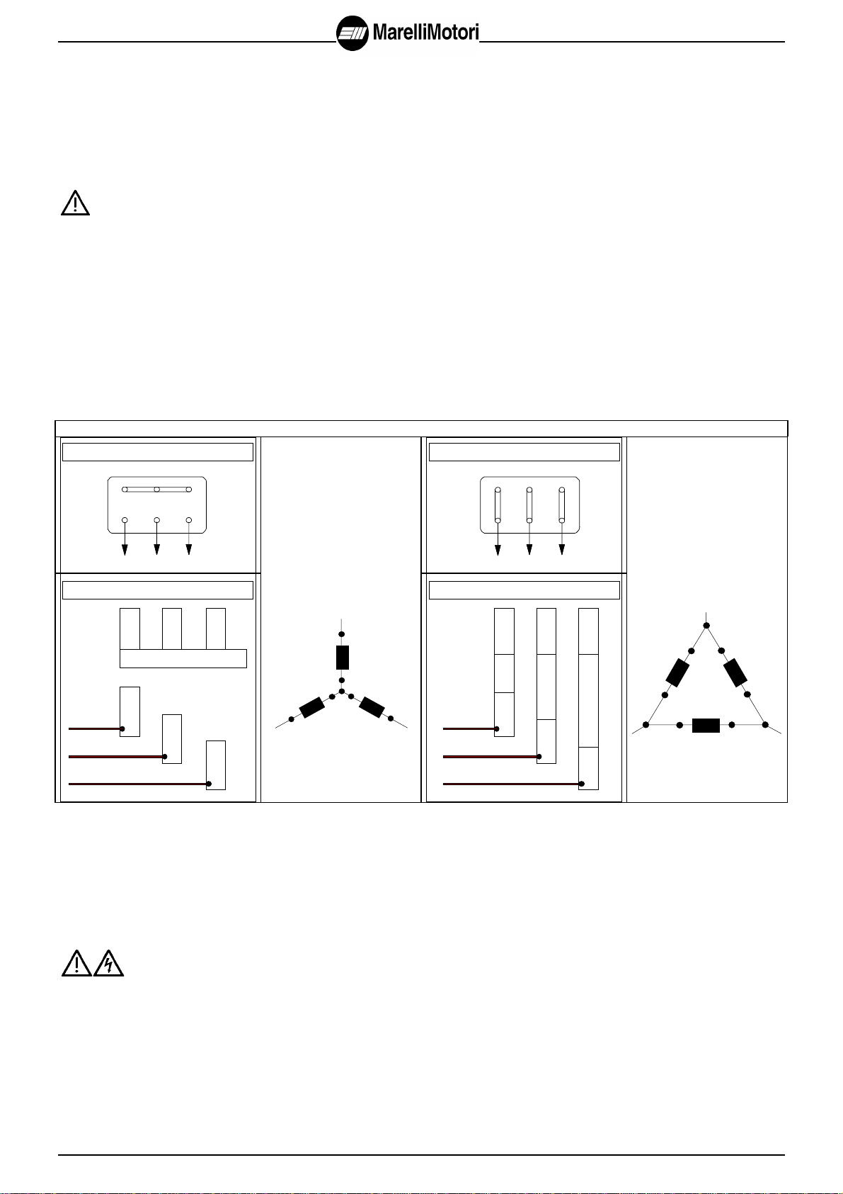
9. SCHEMI DI COLLEGAMENTO...........................................................................................................................................................52
10. DISCO RADDRIZZATORE................................................................................................................................................................56
11. SMALTIMENTO ................................................................................................................................................................................59
AVVERTENZE GENERALI SULLA SICUREZZA
Le macchine elettriche sono componenti destinati ad operare in aree industriali (incorporate in macchine /impianti) e quindi non
possono essere trattate come prodotti per la vendita al minuto .
Le istruzioni fornite riportano pertanto le informazioni atte ad essere utilizzate da personale qualificato.
Esse devono essere integrate dalle disposizioni legislative e dalle norme Tecniche vigenti e non sostituiscono alcuna norma di impianto
ed eventuali prescrizioni aggiuntive, anche non legislative, emanate comunque ai fini della sicurezza.
Macchine in esecuzione speciale o con varianti costruttive possono differire nei dettagli rispetto a quelle descritte.
In caso di difficoltà si prega di contattare l'organizzazione della MarelliMotori specificando:
- tipo della macchina
- codice completo della macchina
- numero di matricola.
PERICOLO
Le macchine elettriche rotanti sono macchine che presentano parti pericolose in quanto poste sotto tensione o dotate di
movimento durante il funzionamento. Pertanto:
- un uso improprio
- la rimozione delle protezioni e lo scollegamento dei dispositivi di protezione
- la carenza di ispezioni e manutenzioni
possono causare gravi danni a persone o cose.
Il responsabile della sicurezza deve perciò assicurarsi e garantire che la macchina sia movimentata installata, messa in servizio,
gestita, ispezionata, manutentata e riparata esclusivamente da personale qualificato, che quindi dovrà possedere:
- specifica formazione tecnica ed esperienza
- conoscenza delle Norme tecniche e delle leggi applicabili
- conoscenza delle prescrizioni generali di sicurezza, nazionali, locali e dell'impianto
- capacità di riconoscere ed evitare ogni possibile pericolo.
I lavori sulla macchina elettrica devono avvenire su autorizzazione del responsabile della sicurezza, a macchina ferma,
scollegata elettricamente dalla rete, (compresi gli ausiliari, come ad es. le scaldiglie anticondensa).
Poichè la macchina elettrica oggetto della fornitura costituisce un prodotto destinato ad essere impiegato in aree industriali, misure di
protezione aggiuntive devono essere adottate e garantite da chi è responsabile dell'installazione nel caso necessitino
condizioni di protezione più restrittive.
Il generatore elettrico è un componente che viene meccanicamente accoppiato ad un'altra macchina (singola o costituente parte di un
impianto); è' pertanto responsabilità di chi esegue l'installazione garantire che durante il servizio ci sia un adeguato grado di protezione
contro il pericolo di contatti con parti in movimento che restino scoperte e che sia interdetto un accostamento pericoloso per le persone
o le cose.

ITALIANO
3
Nel caso che la macchina presenti caratteristiche anomale di funzionamento (tensione erogata eccessiva o ridotta, incrementi delle
temperature, rumorosità, vibrazioni), avvertire prontamente il personale responsabile della manutenzione.
ATTENZIONE: Nel presente manuale sono inseriti degli autoadesivi relativi ad indicazioni per la sicurezza: questi
autoadesivi sono da applicare a cura dell’installatore secondo le indicazioni presenti sul foglio degli adesivi stessi.
1. DESCRIZIONE
Le istruzioni contenute nel presente manuale sono riferite a generatori sincroni M8B. I dati tecnici e le caratteristiche costruttive sono
riportate nel relativo catalogo.
Per il corretto funzionamento ed utilizzo dei generatori è necessario prendere visione delle istruzioni contenute in questo manuale.
I generatori M8B sono generatori sincroni Brushless autoeccitati ed autoregolati, costruiti in conformità alle normative IEC 34-1.
Grado di protezione - caratteristiche
Il grado di protezione e le caratteristiche nominali sono riportate in targa.
Frequenza
I generatori sono previsti per il funzionamento a frequenza 50 o 60 Hz, secondo i dati riportati in targa: per il corretto
funzionamento per l’una o per l’altra frequenza occorre comunque verificare che le tarature del regolatore di tensione siano corrette per
l’utilizzo previsto ed occorre verificare che l’utilizzo sia in accordo con i dati di targa.
Accessori
I generatori possono essere provvisti di vari accessori, a seconda di quanto richiesto in ordine.
2. TRASPORTO E GIACENZA A MAGAZZINO
Il generatore viene spedito pronto per l'installazione. Si raccomanda di esaminarlo accuratamente all'arrivo a destinazione, per
verificare che non sia stato danneggiato durante il trasporto. Eventuali danni visibili devono essere denunciati direttamente al
trasportatore e a MarelliMotori.
Per il sollevamento e la movimentazione del generatore, usare gli appositi golfari.
I golfari disponibili sul generatore sono adatti al sollevamento del solo generatore e non devono essere utilizzati per il
sollevamento del gruppo completo.
Verificare inoltre che siano predisposti mezzi di sollevamento adeguati per il peso del generatore e che siano prese tutte le
misure di sicurezza per la movimentazione.
Se il generatore non viene messo immediatamente in servizio, dovrà essere immagazzinato in un luogo coperto pulito, asciutto e privo
di vibrazioni.
Se rimane per lungo tempo in un locale umido, è opportuno essicare gli avvolgimenti prima della messa in servizio.
I cuscinetti a rotolamento non necessitano di manutenzione durante la giacenza a magazzino; la rotazione periodica dell'albero aiuterà
a prevenire la corrosione da contatto e l'indurimento del grasso.
3. INSTALLAZIONE E MESSA IN SERVIZIO
3.1 Controlli preliminari
Prima dell'installazione:
- verificare che i dati di targa del generatore corrispondano alle caratteristiche dell'impianto
- provvedere a pulire le superfici di accoppiamento, quali le superfici dei giunti e delle flangie (e la sporgenza d’asse
per generatori bisupporto) dalla vernice di protezione.
I generatori monosupporto vengono normalmente spediti con staffa di fissaggio per il trasporto.
Prima dell'installazione, rimuovere tale staffa.
3.2 Prova di isolamento
Se l'alternatore è rimasto inattivo per un lungo tempo, prima della sua messa in funzione è opportuno eseguire una prova di isolamento
verso massa degli avvolgimenti dello statore. Prima di eseguire tale prova è necessario staccare i collegamenti che vanno a dispositivi
di regolazione (RDT o altri dispositivi).
Se la prova, eseguita con Megger o altro strumento simile, mostra che la resistenza di isolamento verso massa è inferiore a 5 Mohm, si
dovrà asciugare l’alternatore e quindi ripetere la prova.
3.3 Equilibratura
Salvo diversa indicazione, i generatori bisupporto sono equilibrati con mezza linguetta applicata all’estremità d’albero, secondo IEC 34-
14.

ITALIANO
4
3.4 Condizioni di installazione
L'alternatore dovrà essere installato in un locale sufficientemente ampio con possibilità di scambio dell'aria direttamente con
l'atmosfera.
E' indispensabile che le aperture di aspirazione e di scarico dell'aria non siano ostruite e che l'esecuzione del piazzamento sia tale da
evitare l'aspirazione diretta dell'aria calda.
Prevedere la possibilità di effettuare ispezioni e manutenzione durante il funzionamento.
3.5 Allineamento
Allineare accuratamente il generatore ed il motore di trascinamento.
Un allineamento impreciso può causare vibrazioni e danneggiamenti dei cuscinetti. E' necessario inoltre verificare che le caratteristiche
torsionali del generatore e del motore siano compatibili. Per consentire l’eventuale verifica di compatibilità (a cura cliente), MarelliMotori
può fornire disegni dei rotori per i controlli torsionali.
Nel caso di generatori monosupporto è inoltre necessario verificare tutte le dimensioni del volano e del coprivolano del motore primo;
verificare inoltre le dimensioni della flangia e del giunto del generatore.
3.6 Collegamento elettrico
I generatori sono normalmente forniti con 6 terminali.
Sono normalmente possibili entrambi i collegamenti stella con neutro e triangolo.
Nel caso venga richiesto espressamente il collegamento a triangolo, per i generatori M8B 400 ed M8B 500, occorre specificarlo in
ordine (vengono allora forniti anche i ponti per il collegamento in morsettiera). Inoltre è necessario che nel cambio di collegamento (da
stella a triangolo) venga verificato il collegamento del regolatore di tensione (ved. schemi applicabili).
Schemi di collegamento per generatori standard
W2 U2 V2
W1V1U1
L1 L2 L3
M8B 315 COLLEGAMENTO A
STELLA W2 U2 V2
W1V1U1
L1 L2 L3
M8B 315 COLLEGAMENTO A
TRIANGOLO
U1
V1
W1
W2 U2 V2
L1
L2
L3
M8B 400 - M8B 500
U2
U1
V2
V1
W1
W2
L1
L2L3
U1
V1
W1
W2 U2 V2
L1
L2
L3
M8B 400 - M8B 500
W2
V1
V2
U1
U2
W1
L1
Gli schemi di collegamento interno dei generatori sono riportati alla fine del presente manuale per i generatori di serie a 6 terminali e
per quelli a 12 terminali (a 9 oppure 12 morsetti, esecuzione su richiesta).
Senso di rotazione
I generatori sono normalmente forniti per funzionamento con senso di rotazione orario (visto dal lato accoppiamento).
Collegamento a terra
All’interno della scatola morsetti è presente un morsetto per il collegamento a terra, mentre un secondo morsetto è posto
su un piede del generatore.
Eseguire la messa a terra con conduttore di rame di sezione adeguata, secondo le norme vigenti.
3.7 Messa in servizio
Prima di mettere in servizio la macchina occorre verificare l’isolamento:
NON SI DEVE METTERE IN FUNZIONE LA MACCHINA SE LA RESISTENZA DI ISOLAMENTO E’ INFERIORE AD 5 MEGAOHM
Prima del primo avviamento, verificare:
- che i bulloni siano adeguatamente stretti
- che l’accoppiamento sia corretto
- che l’aria di raffreddamento sia sufficiente
- che le griglie di protezione siano al loro posto

ITALIANO
5
- per gli alternatori monosupporto, che la coppia di serraggio dei dischi sia corretta.
Verifiche elettriche
Verificare che:
- l’impianto sia dotato di opportune protezioni differenziali, secondo le legislazioni vigenti in materia
- che il collegamento ai terminali della morsettiera siano correttamente eseguiti (morsetti ben stretti)
- che non ci siano inversioni di collegamenti o corto circuiti tra generatore ed interruttori esterni: è opportuno ricordare che
normalmente non esistono protezioni per cortocircuito tra alternatore ed interruttori esterni.
4. MANUTENZIONE
Qualsiasi intervento sulla macchina elettrica deve avvenire su autorizzazione del responsabile della sicurezza, a macchina
ferma ed a temperatura ambiente, scollegata elettricamente dall’impianto o dalla rete, (compresi gli ausiliari, come ad es. le scaldiglie
anticondensa). Devono inoltre essere prese tutte le precauzioni per evitare la possibilità che la macchina venga riavviata
inavvertitamente durante le fasi di manutenzione.
4.1 Intervalli di ispezione e manutenzione
La frequenza delle ispezioni può variare da caso a caso e dipende dalla importanza dell’impianto e dalle condizioni ambientali e di
utilizzo.
Come regola generale si raccomanda una prima ispezione dopo circa 500 ore di funzionamento ( e comunque non oltre un anno):
successivamente almeno in occasione degli interventi di manutenzione del motore termico.
In occasione delle ispezioni si verificherà che:
- il generatore funzioni regolarmente senza rumori o vibrazioni anomale, che denotino danneggiamento dei cuscinetti
- i dati funzionali siano corretti
- l’ingresso dell’aria sia libero
- i cavi di collegamento non presentino segni di deterioramento e le connessioni elettriche siano fermamente serrate
- che tutti i bulloni di fissaggio siano adeguatamente stretti.
4.2 Manutenzione dei cuscinetti
Per i generatori M8B 315 e M8B 400 il cuscinetto Lato D (lato accoppiamento) è di tipo rilubrificabile, dotato di ingrassatore a testa
esagonale UNI 7662. L’intervallo di lubrificazione è di 4000 ore con 50 grammi di grasso.
Il cuscinetto Lato N (lato opposto accoppiamento) è del tipo prelubrificato in fase di montaggio, con una quantità di grasso che
acconsente un lungo periodo di funzionamento. Tale periodo ha una durata, in condizioni normali d'uso, di circa 10.000 ore o 2 anni di
utilizzo in condizioni normali.
Per i generatori M8B 500 entrambi i cuscinetti sono del tipo rilubrificabile, con ingrassatore a testa esagonale UNI 7662.
Per i normali utilizzi consigliamo i seguenti tipi di grasso:
MOBIL OIL - MOBILUX 3 / SHELL - ALVANIA 3 / AGIP - GR MU 3 / ESSO - EACON 3
La mescolanza di grassi diversi (addensante, tipo di olio base) ne riduce la qualità e deve essere quindi evitata.
Una lubrificazione eccessiva può causare surriscaldamento dei cuscinetti.
In occasione della revisione completa del gruppo, lavare i cuscinetti e le camere di raccolta grasso con adatto solvente e rinnovare la
riserva di grasso.
4.3 Operazioni di smontaggio
Prima di smontare la macchina, studiare le viste in sezione. Verificare inoltre che siano predisposti mezzi di
sollevamento adeguati per i pesi dei componenti da movimentare.
Verificare inoltre che siano prese tutte le misure di sicurezza per la movimentazione.
Quindi procedere a disaccoppiarla dal motore primo, togliendo i dadi di fissaggio dei piedi e della flangia e scollegando i terminali dei
cavi di potenza dalla morsettiera. Allontanare quindi l'alternatore dal motore primo.
Scollegare i conduttori rosso (+) e blu (-) che vanno dal regolatore allo statore eccitatrice.
Togliere la protezione (45) dello scudo Lato N.
Per i generatori M8B 315 e M8B 400:
Per i generatori bisupporto:
- smontare il giunto dall’albero e togliere la chiavetta dalla sporgenza d’asse
- togliere le viti che fissano il coperchietto interno del cuscinetto lato D (accoppiamento)
- togliere le viti che fissano gli scudi (4-5) alla cassa, togliere gli scudi facendo attenzione che il rotore non cada pesantemente sullo
statore
- sfilare il rotore (3) dal lato accoppiamento, avendo cura di sostenerlo durante questa operazione, per evitare lo strisciamento del
rotore stesso sullo statore.
Per i generatori monosupporto:
- togliere le viti di fissaggio dello scudo Lato N, togliere lo scudo stesso e sfilare quindi il rotore (3) dal lato accoppiamento, avendo
cura di sostenerlo durante questa operazione, per evitare lo strisciamento del rotore stesso sullo statore.
Tener presente che lo statore eccitatrice è fissato allo scudo Lato N; evitare quindi che durante le operazioni di smontaggio siano
danneggiati gli avvolgimenti della eccitatrice.

ITALIANO
6
Per i generatori M8B 500:
Operazioni di smontaggio dal lato opposto accoppiamento
-Togliere la protezione (45, 33) dello scudo Lato N (5)
-Scollegare i cavi dal disco raddrizzatore (119) e smontare il disco raddrizzatore stesso
-Staccare dalla morsettierina ausiliaria (sullo statore eccitatrice) i terminali del circuito di eccitazione che vanno alle scatole morsetti
-Smontare lo statore eccitatrice (110) dopo aver estratto le viti che lo fissano allo scudo. Fare attenzione che lo statore eccitatrice
non danneggi gli avvolgimenti di eccitatrice durante tale operazione
-Smontare il grano di bloccaggio (504) del rotore eccitatrice
-Sfilare il rotore eccitatrice (100) servendosi di opportuni tiranti (M12)
-Togliere le viti di fissaggio del coperchietto interno (142) del cuscinetto Lato N
-Togliere le viti che fissano lo scudo Lato N (5) alla cassa
-Estrarre lo scudo lato opposto (5). In questa fase occorre aver cura di sostenere il rotore principale (3) del generatore in modo
che non cada pesantemente sullo statore
-Togliere l’anello elastico (305) che fissa la valvola di lubrificazione rotante (143) all’albero, ed estrarre la valvola di lubrificazione stessa
-Nel caso occorra smontare completamente il cuscinetto Lato N (202) adoperare un opportuno estrattore avendo cura che i punti di
ancoraggio delle braccia dell’estrattore siano sull’anello interno del cuscinetto; il punto di appoggio della base dell’estrattore (in testa
all’albero) inoltre dovrà essere posizionata in modo che non possa danneggiare i cavi uscenti in testa all’albero (interporre se
necessario un opportuno distanziale, in modo che i cavi non siano sottoposti a compressioni).
Operazioni di smontaggio dal lato accoppiamento
Per i generatori bisupporto:
- Smontare il giunto dall’albero e togliere la chiavetta (223) dalla sporgenza d’asse
-Togliere le viti che fissano il coperchietto interno (131) del cuscinetto Lato D
-Togliere le viti che fissano lo scudo Lato D (4) alla cassa
-Estrarre lo scudo lato accoppiamento (4). In questa fase occorre aver cura di sostenere il rotore principale (3) del generatore in modo
che non cada pesantemente sullo statore
-Togliere i grani che fissano la valvola di lubrificazione rotante (132) all’albero, ed estrarre la valvola di lubrificazione stessa
-Sfilare il rotore (3) dal lato accoppiamento, avendo cura di sostenerlo durante questa operazione, per evitare lo strisciamento del rotore
stesso sullo statore.
Per i generatori monosupporto:
-Togliere le viti di fissaggio dello scudo Lato N, togliere lo scudo stesso e sfilare quindi il rotore (3) dal lato accoppiamento, avendo
cura di sostenerlo durante questa operazione, per evitare lo strisciamento del rotore stesso sullo statore.
Per tutti i generatori:
Per lo smontaggio dei cuscinetti adoperare un apposito estrattore.
Dove è presente il coperchietto interno, servirsi del coperchietto stesso.
4.4 Operazioni di rimontaggio
Eseguire in senso inverso la sequenza di operazioni descritte per lo smontaggio. Se gli scudi sono stati smontati, le viti di fissaggio
degli scudi stessi devono essere riposizionate dopo aver spalmato il filetto con LOCTITE.
Se il cuscinetto è stato smontato, usarne sempre uno nuovo.
Per facilitare il montaggio i cuscinetti devono essere riscaldati a circa 70-80 °C.
ATTENZIONE - Il montaggio dei cuscinetti deve essere effettuato con la massima cura.

ITALIANO
7
5. REGOLATORE DI TENSIONE
Il generatore è provvisto di regolatore automatico di tensione (RDT).
Il regolatore è dotato di potenziometri per adattare il suo funzionamento alle diverse condizioni di utilizzo del generatore.
In particolare il regolatore è dotato di circuiti di antipendolamento adattabili per consentire l'utilizzo in una vasta gamma di impianti.
Il regolatore è dotato inoltre di circuiti interni appositi di protezione per bassa frequenza, che permettono il funzionamento a vuoto a
velocità inferiore a quella nominale.
ATTENZIONE: è sconsigliabile il funzionamento a carico a frequenza (giri) inferiore alla nominale: questo tipo di servizio
rappresenta un sovraccarico per tutta la parte di eccitazione del generatore.
Filtro antidisturbo radio
Il regolatore di tensione è internamente provvisto di filtro antidisturbo radio, che permette di contenere i disturbi radio emessi da
generatori MarelliMotori entro i limiti stabiliti dalle normative Europee per ambienti industriali.
Fusibile
All'interno del RDT è disposto un fusibile di protezione.
In caso di sostituzione, devono essere sempre utilizzati fusibili super-rapidi ad alto potere di interruzione, per tensione nominale 500V e
corrente nominale di 10A.
Connessioni del regolatore
Il RDT è collegato ai terminali del generatore e all'eccitatrice per mezzo di morsettiera di tipo FAST-ON.
Uso dei potenziometri
STAB - potenziometro di taratura della stabilità
⇒aumenta la velocità di risposta, diminuisce la stabilità ⇒diminuisce la velocità di risposta, aumenta la stabilità
FREQ - potenziometro di taratura dell'intervento della protezione per bassa frequenza
Normalmente è tarato per ridurre l'eccitazione quando la velocità scende oltre il 10% sotto la velocità nominale relativa a 50Hz.
Tagliando il ponte tra i terminali “60-Hz” si ottiene l'intervento appropriato per funzionamento a 60 Hz.
⇒diminuisce la frequenza di intervento ⇒aumenta la frequenza di intervento
VOLT - potenziometro per la regolazione della tensione di uscita dei generatori
Tale potenziometro interno consente una notevole escursione di tensione (tra 350 e 450 V, oppure tra 170 e 270 V): in caso di
intervento su tale potenziometro, la tensione non deve essere modificata oltre il 5% rispetto a quella di targa.
In caso si voglia ottenere una regolazione più fine, oppure controllare a distanza la tensione, o ancora si voglia limitare il campo di
variazione della tensione, occorre aggiungere un potenziometro esterno.
⇒aumenta la tensione ⇒diminuisce la tensione
STAT - potenziometro di taratura dello statismo
Quando due o più generatori devono funzionare in parallelo, occorrerà verificare che la tensione a vuoto degli stessi sia uguale, che il
ponte tra i morsetti A-B sia aperto e che essi presentino la medesima caduta di tensione passando da vuoto a carico.
Per controllare il corretto funzionamento di tale dispositivo di statismo, si deve verificare che, passando da vuoto a pieno carico con
cosfì 0.8, la macchina presenti una caduta di tensione del 4%.
Qualora si osservi un innalzamento della tensione occorre invertire i conduttori del trasformatore di corrente sui morsetti A-B.
Qualora occorra variare la caduta di tensione, si dovrà ruotare il potenziometro come indicato di seguito.
⇒aumenta lo statismo ⇒diminuisce lo statismo
Nella marcia in singolo i morsetti A e B devono essere cortocircuitati.

ITALIANO
8
P/Q
-+
al VARICOMP
60/Hz
A/B
68M
∼230
-0U+
400
300
Riferimento di
tensione Alimentazione
Statore
eccitatrice
STAB FREQ VOLT STAT
mini di
p
1÷5
12345
On
Off
Uso dei mini dip
Le caratteristiche di stabilità si possono modificare anche agendo sui microinterruttori disposti sul regolatore stesso.
Essi agiscono su condensatori modificando in modo discontinuo le costanti di tempo dei circuiti del regolatore.
dip 1
pos.ON ⇒aumento tempo di risposta
dip 2
pos.ON ⇒aumento tempo di risposta
dip 3
pos.ON ⇒protezione bassa frequenza standard pos.OFF ⇒protezione bassa frequenza con funzione
proporzionale V/f
dip 4
- non abilitati
dip 5
5.1. Protezione termica
I generatori sono muniti di dispositivo di protezione contro i sovraccarichi pericolosi. Questo dispositivo è collegato ai morsetti ausiliari
E-C, e può essere gestito dall'utilizzatore per comandare un segnale di blocco o di allarme.
I due terminali E-C rendono disponibile un contatto normalmente chiuso per 250 V - 5 A.
Questo dispositivo non agisce sulla regolazione di tensione (RDT).
5.2. Reostato per la regolazione a distanza della tensione
Per tutti i generatori tale reostato può essere inserito fra i terminali “P-Q” (terminali FAST-ON) della morsettiera ausiliaria del regolatore,
dopo aver tolto il ponticello che cortocircuita normalmente tali morsetti.
Il potenziometro esterno va inserito con il cursore in posizione intermedia e quindi si agisce sul potenziometro interno del RDT in modo
da ottenere la tensione nominale.
Tale potenziometro deve avere una resistenza di circa 1000 Ohm ed una potenza minima di 2 W.
5.3. Comando manuale della eccitazione
Nel caso di avaria al regolatore di tensione, è possibile utilizzare l'alternatore con comando manuale, purchè si disponga di una
qualsiasi sorgente a corrente continua a 24 V.
R
24 V
BLU
ROSSO
TERMINALI
AVVOLGIMENTO
STATORE
ECCITATRICE
Questa sorgente può essere rappresentata da una batteria di accumulatori o da un dispositivo di trasformazione e raddrizzamento della
tensione di uscita dell'alternatore.

ITALIANO
9
Allo scopo, è necessario realizzare lo schema della figura precedente, eseguendo le seguenti operazioni:
- scollegare dal regolatore i due terminali FAST-ON rosso (+) e blu (-) che collegano il regolatore stesso allo statore eccitatrice
- alimentare questi due terminali con la sorgente in corrente continua disponendo in serie un reostato R
- la regolazione della tensione in uscita dall'alternatore si ottiene agendo sul reostato R.
ATTENZIONE Man mano che il carico aumenta, effettuare la compensazione aumentando manualmente l'eccitazione.
Prima di togliere il carico, ridurre l'eccitazione.
Utilizzare la seguente tabella per la scelta del reostato:
Generatore I max
[A] Resistenza max del reostato
[Ω]
M8B 315 4 80
M8B 400 6 80
M8B 500 8 80
5.4. Dispositivo di sovraeccitazione VARICOMP
Il dispositivo è composto da un trasformatore di corrente e da una scheda elettronica e costituisce un dispositivo per la
sovraeccitazione in caso di bruschi sovraccarichi o in caso di corto circuito.
Il trasformatore amperometrico fornisce una corrente proporzionale a quella di carico; tale corrente, raddrizzata, è inviata al circuito di
eccitazione, in aggiunta alla eccitazione fornita dal RDT.
Il trasformatore di corrente viene comunque cortocircuitato in condizioni di carico normale, in modo da non incidere sulla regolazione e
viene inserito nel sistema di regolazione solo quando la tensione scende al di sotto del 70% (circa) del valore nominale.
Nel caso si osservi un aumento sensibile di tensione nel funzionamento a carico, si può procedere a ritarare l'intervento del dispositivo
di sovraeccitazione agendo sul potenziometro interno della scheda, ruotandolo in senso antiorario.
TA
+-∼
A
1
B1
al RDT
Potenziometro regolazione livello di intervento
sovraeccitazione
⇒intervento a tensione maggiore
⇒intervento a tensione minore

ITALIANO
10
6. RICERCA GUASTI ED INTERVENTI
INCONVENIENTE POSSIBILE CAUSA INTERVENTO
(da eseguire sempre a macchina ferma)
L'alternatore non si eccita.
La tensione a vuoto è
inferiore al 10% della
nominale.
a) rottura dei collegamenti.
b) guasto sui diodi rotanti.
c) interruzione dei circuiti di eccitazione.
a) controllo e riparazione.
b) Controllo dei diodi e sostituzione se interrotti o in corto
circuito.
c) controllo della continuità sul circuito di eccitazione.
L'alternatore non si eccita
(tensione a vuoto intorno
al 20%-30% della
nominale).
La tensione non risente
dell'intervento sul
potenziometro del RDT.
a) Intervento del fusibile.
b) Rottura dei collegamenti sullo statore
eccitatrice.
c) Errata alimentazione del circuito di
eccitazione.
a) Sostituire il fusibile con quello di scorta. Se il fusibile si
interrompe nuovamente, controllare se lo statore
eccitatrice è in corto circuito. Se tutto è normale, sostituire
il RDT.
Controllare il dispositivo Varicomp, se presente ed
eventualmente sostituirlo.
b) Verifica della continuità sul circuito di eccitazione.
c) Scambiare tra di loro i due fili provenienti
dall'eccitatrice.
Tensione a carico inferiore
alla nominale (tensione tra
50 e 70% della nominale).
a) Velocità inferiore alla nominale.
b) Potenziometro della tensione non
tarato.
c) Fusibile interrotto.
d)Guasto del RDT.
e)Guasto del dispositivo Varicomp (se
presente).
a) Controllo del numero di giri (freq.).
b) Ruotare il potenziometro finché la tensione non si
riporta al valore nominale.
c) Sostituire il fusibile.
d)Scollegare il regolatore di tensione e sostituirlo.
e)Controllare il dispositivo Varicomp, se presente ed
eventualmente sostituirlo.
Tensione troppo alta. a) Potenziometro V non tarato.
b) Guasto del RDT. a) Ruotare il potenziometro finché la tensione non si
riporta al valore nominale.
b) Sostituzione del RDT.
Tensione instabile. a) Giri variabili del Diesel.
b) Potenziometro di stabilità del RDT non
tarato.
c) Guasto del RDT.
a) Controllo dell'uniformità di rotazione. Controllo del
regolatore del Diesel.
b) Ruotare il potenziometro di stabilità finché la tensione
ritorna stabile.
c) Sostituzione del RDT.
7. PARTI DI RICAMBIO - NOMENCLATURA
Pos Particolare Tipo / Codice
M8B 315 M8B 400 M8B 500
201 Cuscinetto lato D (lato accoppiamento) 6319 C3 / 346151095 6324 C3 / 346151120 6328 C3 / 346151140
202 Cuscinetto lato N (lato opposto accopp.) 6315-Z C3 / 346113275 6318-Z C3 / 346113290 6326 C3 / 346151130
6 Regolatore di tensione M40FA610A
12 Varicomp M40FA621A
7 Fusibile 10A-500V (6,3x32) 963823010
309 Diodo rotante inverso 71 HFR 120 / 963821170 71 HFR 120 / 963821056
310 Diodo rotante diretto 71 HF 120 / 963821171 71 HF 120 / 963821057
311 Scaricatore / filtro M40FA990A
307 Filtro M50FA873A
308 Scaricatore 963820007
119 Raddrizzatore rotante M40FA500A M50FA301A

ENGLISH
11
CONTENTS
GENERAL SAFETY WARNING ..................................................................................................................................................11
1. DESCRIPTION ........................................................................................................................................................................12
2. TRANSPORT AND STORAGE.................................................................................................................................................12
3. INSTALLATION AND COMMISSIONING.................................................................................................................................12
3.1 Check before installation......................................................................................................................................................12
3.2. Insulation test ......................................................................................................................................................................12
3.3. Balancing.............................................................................................................................................................................13
3.4. Installation conditions..........................................................................................................................................................13
3.5. Alignment.............................................................................................................................................................................13
3.6. Electrical connection............................................................................................................................................................13
3.7. Commissioning....................................................................................................................................................................14
4. MAINTENANCE........................................................................................................................................................................14
4.1 Inspection and maintenance intervals..................................................................................................................................14
4.2. Maintenance of bearings.....................................................................................................................................................14
4.3. Dismantling operations........................................................................................................................................................14
4.4. Reassembly operations.......................................................................................................................................................15
5. VOLTAGE REGULATOR..........................................................................................................................................................16
5.1. Thermal protection device...................................................................................................................................................17
5.2. Rheostat for remote voltage setting.....................................................................................................................................17
5.3. Instructions for manual control of generators......................................................................................................................17
5.4. Overboosting device VARICOMP........................................................................................................................................18
6. TROUBLE SHOOTING AND REPAIRS....................................................................................................................................19
7.SPARE PARTS - NOMENCLATURE.........................................................................................................................................19
8. SECTION..................................................................................................................................................................................48
9. CONNECTION DIAGRAMS......................................................................................................................................................52
10.ROTATING RECTIFIER ..........................................................................................................................................................56
11.DISPOSAL.............................................................................................................................................................................. 59
GENERAL SAFETY WARNING
The generators which are the subject of these “instructions” are components designed for use in industrial areas (machines/plants) and
therefore cannot be treated as retail goods.
This documentation consequently contains information that is only suitable for use by qualified personnel. It must be used in compliance
with the regulations, laws and technical Standards in force and cannot under any circumstances take the place of plant standards or
additional prescriptions, including any which are not legally enforceable, which have been issued for the purpose of ensuring safety.
Machines built to customer specifications or with constructional differences may differ in detail from the generators described herein. If
you encounter any difficulties please do not hesitate to contact Marelli Motori, specifying:
- the type of machine
- the full code number of the generator
- the serial number
DANGER
Electric rotating machines have dangerous parts: when operating they have live and rotating components. Therefore:
- improper use
- the removal of protective covers and the disconnection of protection devices
- inadequate inspection and maintenance
can result in severe personal injury or property damage.
The person responsible for safety must therefore ensure that the machine is transported, installed, operated, maintained and repaired
by qualified personnel only, that must have:
- specific training and experience
- knowledge of applicable standards and laws
- knowledge of the general safety regulations, national and local codes and plant requirements
- the skill to recognise and avoid possible danger.
All maintenance and inspection operations must be carried out only with the authorisation of the person responsible for
safety, with the machine at a standstill, disconnected from the supply (including the auxiliary circuits such as the anti-
condensation heaters).
As the electric machine is a product to be installed in industrial areas, additional protective measures must be taken and assured
by the person responsible for the installation, if stricter protection conditions are required.

ENGLISH
12
As the electric generator is a component to be coupled to another machine, it is the responsibility of the installation engineer to ensure,
during operation, proper protection against the risk of contact with bare rotating parts and to prevent people or things from approaching
the machine.
If the machine shows deviations from the normal performance (excessive or too low voltage, increase in temperature, noise and
vibrations) promptly advise the personnel responsible for maintenance.
WARNING: Here enclosed with this “instructions manual” there are self adhesive leaflets which are reporting symbols
for security: the self adhesive leafletsare to be applied to the generator surface, at the customer’s charge, according the
instructions presented on the sheet of the self-adhesive.
1. DESCRIPTION
These instructions refer to three-phase synchronous generators series M8B. Technical data and constructive details are given in the
catalogue.
In order to obtain the proper working of generators it is necessary to read carefully all included instructions.
The generators M8B are synchronous generators, brushless type, self excited and self regulated, manufactured according to the
standards indicated on the name plate (IEC 34-1).
Degree of protection - characteristics
The protection degree of the generators and the rated data are shown on the name plate.
Frequency
The generators are suitable for operation at 50 and 60 Hz, according to the data reported on the name-plate: for correct operation
for 50 or for 60 Hz, it is necessary to verify that the settings of the voltage regulator are proper for the required operation and that the
use of the generator is in accordance with the values on the name-plate.
Accessories
According to the customer’s order the generators can be equipped with accessories, such as anticondensation heaters, thermistors,
etc.
2. TRANSPORT AND STORAGE
The generator is shipped ready for installation. It should be carefully inspected on arrival in order to verify if damage has occurred
during transport; if any, they should be referred directly to the haulier and to MarelliMotori
For lifting and handling the purpose made eyebolts must be used.
The lifting eyes are designed to support only the weight of the generator and they are not to be used for lifting the complete
gen-set that incorporates the generator. Check that the lifting means available are suitable for the movement of all parts which
have to be handled. Check also that all the working conditions are suitable to operate without dangers for safety of personnel.
If the generator is not put into operation immediately, it should be stored in a covered area or in a clean, dry and vibration-free place. If
it is stored in a damp ambient, the windings should be dried before using it.
The rolling contact bearings do not require maintenance during storage; periodic rotation of the shaft will help to prevent contact
corrosion and hardening of the grease.
3. INSTALLATION AND COMMISSIONING
3.1 Check before installation
Before installing the generator
- make sure that name plate data corresponds to the power supply and operating conditions and that the installation
complies with the manufacturer’s recommendations
- clean any protecting varnish from all connecting surfaces (such as surface of couplings and flanges and shaft
extension for two-bearing generators)
Single bearing generators are shipped with a rotor securing plate, fixing the coupling to the flange. Before installation, remove the
plate. During assembly operations, make sure the preloading spring remains in place.
3.2. Insulation test
If the alternator has been kept in storage for a long period of time, it is a good practice to test the stator windings for ground insulation
before starting up.
Before doing this test, it is necessary to disconnect the voltage control system (AVR or similar devices).

ENGLISH
13
If this test, performed using a ohmmeter or another similar instrument, shows that ground resistance is below 5 Mohm, it is necessary
to dry the generator and then the test should be repeated.
3.3. Balancing
Unless otherwise indicated the rotor is balanced dynamically with a half-key fitted on the shaft extension, in compliance with IEC 34-14.
3.4. Installation conditions
Install the generator in a ventilated room. If installed in closed areas the alternators should have a possibility to exchange the cooling air
directly with atmosphere. Air outlet and inlet openings should not be obstructed: provisions should be taken to prevent obstacles from
obstructing ventilation openings. The inlet of warm air should be avoided.
Provision should be taken to make inspection and maintenance easy when the generator is installed or during operation.
3.5. Alignment
Carefully align the generator and the driving machine.
Inaccurate alignment may lead to vibrations and damage of the bearings.
It is also necessary to verify that the torsional characteristics of generator and driving machine are compatible. In order to allow
torsional analysis calculation (at customer’s charge); MarelliMotori can provide rotor drawings for torsional analysis purposes.
For single bearing generators it is further necessary to verify all dimensions of the flywheel and flywheel housing. Furthermore it is
necessary to check the dimensions of the coupling and of the flange on the generator.
3.6. Electrical connection
Standard generators are supplied with 6 leads.
Terminal arrangement permits star and delta connection, according to following diagrams.
If delta connection is strictly required (for 400 and 500 framesizes), it is necessary to specify it in the order (in such case the connection
bridges to perform the connection will be supplied).
It is anyway necessary, when changing the connection from star to delta, to check and modify the connection to the voltage regulator,
according applicable diagrams.
Wiring diagrams for standard generators
W2 U2 V2
W1V1U1
L1 L2 L3
M8B 315 STAR CONNECTION
W2 U2 V2
W1V1U1
L1 L2 L3
M8B 315 DELTA CONNECTION
U1
V1
W1
W2 U2 V2
L1
L2
L3
M8B 400 - M8B 500
U2
U1
V2
V1
W1
W2
L1
L2L3
U1
V1
W1
W2 U2 V2
L1
L2
L3
M8B 400 - M8B 500
W2
V1
V2
U1
U2
W1
L1
Internal connection diagrams are shown at the end of manual for standard generators with 6 terminals and for those with 12 leads (9 or
12 terminals)
Direction of rotation
Generators are normally supplied to operate correctly when rotating clockwise (looking from shaft end side).
Grounding
Inside the terminal box there is a terminal for grounding, and a second terminal is on a foot of the generator. Grounding has
to be carried out using a copper wire of suitable size, in compliance with applicable standards.
3.7. Commissioning
Before starting up check insulation resistance:
THE GENERATOR MUST NOT BE OPERATED IF INSULATION RESISTANCE IS BELOW 5 MEGAOHM

ENGLISH
14
Before first starting up, check:
- If fixing bolts are securely fixed
- that the alignment and coupling is correct
- that the ventilation air is sufficient
- that the protection grids are in place
- for single bearing generators, that the bolts of the disks are fixed with the correct torque.
Electrical checks
Verify that
- the plant is provided with the correct electrical protection devices, according to applicable standards
- that the connection to the terminal block is correctly performed (bolts of terminals properly tightened).
4. MAINTENANCE
For safety purposes it is necessary that any testing or maintenance carried out on electrical machine are performed by
qualified and authorised personnel, and all operation must be performed when the machine is stopped, at ambient temperature and
disconnected from any supply source (including the auxiliary circuits such as the anti-condensation heaters). Furthermore all
measures must be taken to avoid restarting of gen-set during maintenance.
4.1 Inspection and maintenance intervals
Inspection and maintenance should take into account the importance of the plant ambient conditions (dust etc.) and operating
conditions.
As a general rule, the machine should be subjected to a first inspection after approx. 500 operating hours (in any case not more than 1
year) and subsequent inspections when performing maintenance on prime mover.
When performing inspection check that:
- The generator operates smoothly, without noise or irregular vibrations due to bearing deterioration
- The operating data complies with that detailed on the rating plate
- The air inlet openings are not obstructed
- The supply cables show no signs of deterioration and connections are firmly tight
- The electrical connections are in perfect condition (undamaged)
- Screws and nuts are firmly tightened.
4.2. Maintenance of bearings
For M8B 315 and M8B 400 generators:
the D.End bearing is of regreasing type. The regreasing devices are according to UNI 7662.
Lubrication interval is 4.000 hours with 50 grams of grease.
The N.D.End bearing is prelubricated; the first filling of grease is sufficient for 10.000 hours of operation in normal conditions.
For M8B 500 generators both bearings are of regreasing type. The regreasing devices are according to UNI 7662.
Lubrication interval is 4.000 hours with 50 grams of grease.
We recommend the following types of grease:
MOBIL OIL - MOBILUX 3 / SHELL - ALVANIA 3 / AGIP - GR MU 3 / ESSO BEACON 3
Mixing of different greases (thickeners, basic oil) reduce the quality of grease and therefore has to be avoided.
An excessive lubrication or wrong quantity of grease may cause overheating of bearings.
In occasion of complete overhaul of the gen-set, remove the used grease and wash the bearings with solvent before regreasing.
In case of complete overhaul of gen-set, the bearing of the generator should be changed.
4.3. Dismantling operations
Before dismantling the machine, examine the views in cross-section.
Check that the lifting means available are suitable for the movement of all parts which have to be handled.
Check also that all the working conditions are suitable to operate without dangers for safety of personnel.
Then uncouple the generator from the prime mover, removing the bolts securing the flange and feet; remove the bolts fixing the
coupling and disconnect the terminals of the power leads on the terminal board.
Next, remove the generator from the prime mover.
Disconnect the leads red (+) and blue (-) connecting the exciter stator to the voltage regulator.
Remove the guard protecting the generator (45).
For M8B 315 and M8B 400 generators:
For two bearing generators:
- remove the half coupling from shaft extension and remove the key (223)
- remove the bolts fixing the shields (4-5) to the frame, then remove the shields having care to sustain the rotor in order it will not
fall heavily on the stator
- using proper lifting means, remove the rotor (3) from the main stator, through the D.E. side, taking special care to avoid any
damage to the windings.
For single bearing generators:

ENGLISH
15
- remove the bolts fixing the N.D.E. shield to the frame and dismantle the shield
The rotor can be extracted from the stator, from D.E. side.
It should be remembered that the exciter stator is fixed to the N.D.E. endshield: special care should be taken to avoid any damage to its
windings when removing the N.D.E. shield; furthermore be sure the connections or the exciter stator are free to slide out from terminal
box.
If a bearing needs to be replaced, remove it with a suitable puller.
For M8B 500 generators:
Dismantling operations on N.D.E. side (on side opposite to shaft ext.).
-Remove the cover (45, 33) protecting the N.D.E. side
-Disconnect all the wiring from the rotating rectifier and then remove the rectifier (119)
-Disconnect the leads connecting the exciter stator to the terminal box (connection terminals are on exciter stator)
-Remove the exciter stator (110) after having removed the screws securing it to the endshield (5). Care should be taken in order
not to damage the winding of exciter rotor or stator during this operation
-Remove the screw (504) fixing the exciter rotor to the shaft
-Remove the exciter rotor (100) by using suitable puller (rods M12)
-Remove the screws fixing the internal bearing cap (142) of the N.D.E. bearing
-Remove capscrews holding the N.D.E. end-shield (5) to the main stator assembly
-Remove the N.D.E. shield (5). During this operation it is necessary to take care to sustain the main rotor in order it will not fall
heavily on the stator.
On the internal side of the bearing some preloading springs are placed on proper holes: it is necessary to collect them in order to
replace them in the proper position during reassembly of the generator.
-Remove the locating ring (305) fixing the rotating lubrication valve (143) to the shaft, and then remove the rotating valve (143)
-In case should be necessary to remove completely the N.D.E. bearing (202), it is necessary to use a proper puller, taking care that the
arms of the puller are pulling on the inner ring of the bearing; further care should be taken that the puller is not damaging the cables
coming out from the shaft hole (in case, insert a proper spacer between puller and shaft end, in order not to press those cables).
Dismantling operations on D.E. side
Remove the guard protecting the generator at the D.E. side (49).
For two bearing generators
-Remove the key (223) from the shaft extension
-Remove the screws fixing the the inner cover of the D.E. bearings (131)
-Remove the screws fixing the D.E. shield (4) to the main stator assembly
-Remove the D.E. shield (4). During this operation it is necessary to sustain the main rotor (3) of the generator in order to avoid it falling
heavily on the stator
-Remove the screws (grains) fixing the rotating lubrication valve (132) to the shaft, and then remove the lubricating valve
-Remove the rotor (3) from D.E. side. During this operation it is necessary to sustain the main rotor (3) of the generator in order to
avoid it sliding on the stator.
For single bearing generators:
-Remove the screws fixing the D.E. shield (4) to the main stator assembly and remove the shield. Remove the rotor (3) from D.E. side.
During this operation it is necessary to sustain the main rotor (3) of the generator in order it will not slide on the stator.
In case of dismantling completely a bearing, a proper puller has to be used: the arms of the puller must be placed in order to act on the
internal ring of the ball bearing or on the inner cover of the bearing (where present).
4.4. Reassembly operations
Carry out the operations described above for dismantling in reverse order. If the end-shield have been removed, the fixing screws have
to be fixed with LOCTITE (on the threaded surface).
If a bearing was removed, always install a new one.
To make assembly easier, the bearings should be heated to about 70-80 °C.
PLEASE NOTE: bearings should be assembled with the utmost care in order not to damage them.
5. VOLTAGE REGULATOR
The generators are provided with automatic voltage regulator (AVR).
The AVR is provided with potentiometers to adapt the characteristics of the AVR to the different operating conditions.
The AVR is provided with adjustable stability circuitry to allow operations in a wide range of applications.
The AVR is equipped also with protecting circuit allowing the generator to operate underspeed if not loaded.
WARNING: it is not advisable to have the generator operating loaded when the frequency (speed) is below the rated value:
this kind of operation is an overload for the whole excitation system of the generator.

ENGLISH
16
Radio interference suppressor
The voltage regulator is internally provided with radio interference suppressor, in order to limit the radio interference from the
generators M8B to within levels stated by C.E. standards for industrial areas.
Fuse
On the AVR there is a protecting fuse. In case it should be necessary to replace it, high speed fuses should be used; in addition
they should have high breaking resistance with a rated voltage of 500V, and rated current of 10A.
Connection of AVR
The AVR is connected to the terminals of the generator and to exciter using FAST-ON terminals.
Use of potentiometers
STAB - potentiometer for stability adjust
⇒decrease response time, decrease stability ⇒increase response time, increase stability
FREQ - potentiometer for changing the low speed protection.
Usually it is set in order to reduce the excitation when the speed is 10 % below the rated value at 50 Hz. By removing the bridge
which is normally shorting terminals “60-Hz”, the low speed protection acts properly for 60 Hz.
⇒decrease frequency of intervention ⇒increase frequency of intervention
VOLT - potentiometer for adjusting the output voltage of the generator.
It allows a wide range of voltage setting (i.e. between 350 and 470 V; or between 170 and 260 V depending on winding
connections)). In case of resetting this potentiometer the voltage has to be set within 5% of the rated voltage of the machine.
In order to obtain a finer regulation, or to adjust the voltage from control panel or to limit the voltage range, it is possible to
insert an external potentiometer
⇒increase voltage ⇒decrease voltage
STAT - potentiometer for changing the droop
In order to obtain a correct sharing of reactive power, when two or more generators are required to operate in parallel, it is
necessary to verify that the no load voltage is the same, that the bridge between “A-B” is open and the voltage droop is the
same for all generators when loaded.
When this unit is inserted the output voltage should show a 4% voltage droop when passing from no load to full load 0.8 p.f.
If the voltage is increasing as the load increases, it is necessary to reverse the leads of the current transformer at the terminals
“A-B”. If necessary, the voltage droop can be reset by acting on the internal potentiometer.
⇒the droop increase ⇒the droop decrease
In single operation the terminals A and B have to be shorted.
P/Q
-+
VARICOMP
60/Hz
A/B
68M
∼230
-0U+
400
300
Voltage
reference Supply
Exciter Stator
STAB FREQ VOLT STAT
mini switch 1÷5
12345
On
Off

ENGLISH
17
Use of microswitches
To change the stability characteristics of the regulator, it is possible to use the microswitches.
In such a way it is possible to insert capacitors on electronic stability circuit, then obtaining step changes in the transient response of
the regulator.
dip 1
pos.ON ⇒speed response becomes slower
dip 2
pos.ON ⇒speed response becomes slower
dip 3
pos.ON ⇒standard low speed protection pos.OFF ⇒proportional low speed protection V/f
dip 4
dip 5 not used
5.1. Thermal protection device
The generators are equipped with a thermal protection device against dangerous overloads. This device is connected to the auxiliary
terminals E-C, and can be used by the customer as command for either alarm or intervention. The terminals E-C have normally closed
contact for 250V - 5A.
This device does not act on regulation system (AVR).
5.2. Rheostat for remote voltage setting
For all generators, that rheostat can be inserted between the auxiliary terminals P and Q (FAST-ON terminals) of the AVR after having
removed the short-circuiting bridge. The external rheostat has to be inserted with its wiper in intermediate position and then the internal
potentiometer of AVR (P1) has to be reset to obtain the nominal voltage.
5.3. Instructions for manual control of generators
If the voltage regulator (AVR) breaks down, a manual control system can be used, when a 24 V D.C. power supply is available.
R
24 V
BLUE
RED
EXCITER
STATOR
WINDING
TERMINALS
This source could consist of a bank of batteries or of a voltage transformer and a rectifier unit connected at the alternator output.
- disconnect the two exciter stator terminals (red wire +, blue wire -) from AVR
- apply the D.C. power supply to these two wires
- set the rheostat R to adjust the alternator output voltage.
WARNING: compensate by manually increasing excitation as the load increases.
Before removing the load, reduce the excitation current
Use the following table to select the rheostat:
Generator I max
[A] Max. resistance of rheostat
[Ω]
M8B 315 4 80
M8B 400 6 80
M8B 500 8 80

ENGLISH
18
5.4. Overboosting device VARICOMP
The overexcitation device is composed of an electronic device and a current transformer (C.T.), and acts in case of sudden overloads
or in case of short circuit.
The current transformer supplies a current proportional to the load current; this current is rectified and then added to the current given
by AVR. The current transformer is normally short circuited and it does not act on excitation in normal operation conditions. The current
transformer is only inserted if the output voltage drops below 70% of rated value.
If the voltage increases as the load is increasing, then the intervention of the Varicomp device has to be modified by using on the
internal potentiometer of the electronic board, by rotating it anticlockwise.
CT
+-∼
A
1
B1
AVR
Potentiometer to modify intervention of the
overboost
⇒intervention at higher voltage
⇒intervention at lower voltage

ENGLISH
19
6. TROUBLE SHOOTING AND REPAIRS
TROUBLE POSSIBLE CAUSE REMEDY
(always to be done with the machine switched off)
The alternator will not
energise (no load voltage
below 10% of rated
voltage)
a) Loose connections
b) Rotating diodes or surge suppressor
broken
c) Excitation circuit shorted or interrupted
a) Check and repair
b) Check the diodes and change in case they are open or
shortcircuited
c) Check the continuity and repair
The alternator will not
energise (no load voltage
20-30% of rated voltage.
Voltage insensitive to AVR
potentiometer's rotation
a) Fuse (on AVR’s supply line) blown
b) Connection's cut on the exciter stator
c) Incorrect connections of exciter stator
a) Replace the fuse with the spare. If the fuse blows again
check if the exciter stator is short circuited. If everything is
correct, change the AVR
b) Check the continuity and repair
c) Reverse the two wires from the exciter stator
Voltage lower then rated
(output voltage between 50
and 70%)
a) Speed less than rated
b) Voltage potentiometer unset
c) Fuse blown
d)Faulty regulator
a) Check rpm (frequency)
b) Rotate the potentiometer until the voltage reaches the
rated value
c) Replace the fuse with spare
d)Disconnect AVR and replace it
Voltage too high a) Potentiometer V unset
b) Faulty regulator a) Rotate the potentiometer until the voltage reaches the
rated value
b) Replace AVR
Unstable voltage a) Diesel engine rpm variations
b) Stability potentiometer unset
b) Faulty regulator
a) Check rpm uniformity. Check the diesel engine governor
b) Act on AVR’s stability potentiometer.
b) Replace AVR
7.SPARE PARTS – NOMENCLATURE
Pos Part Name Type / Code
M8B 315 M8B 400 M8B 500
201 D side (D:E) bearing 6319 C3 / 346151095 6324 C3 / 346151120 6328 C3 / 346151140
202 N side (N.D.E.) bearing 6315-Z C3 / 346113275 6318-Z C3 / 346113290 6326 C3 / 346151130
6 Voltage regulator M40FA610A
12 Varicomp M40FA621A
7 Fuse 10A-500V (6,3x32) 963823010
309 Rotating diode (inverse) 71 HFR 120 / 963821170 71HFR 120 / 963821056
310 Rotating diode (direct) 71 HF 120 / 963821171 71 HF 120 / 963821057
311 Surge suppressor M40FA990A
307 Filter M50FA873A
308 Surge suppressor 963827007
119 Complete rotating rectifier M40FA500A M50FA301A

FRANÇAIS
20
INDEX
CONSIGNES DE SECURITE..................................................................................................................................................................20
1. DESCRIPTION....................................................................................................................................................................................21
2. TRANSPORT ET STOCKAGE EN MAGASIN.....................................................................................................................................21
3. INSTALLATION ET MISE EN SERVICE.............................................................................................................................................21
3.1. Contrôles préliminaires ..................................................................................................................................................................21
3.2. Test d’isolement.............................................................................................................................................................................21
3.3. Equilibrage.....................................................................................................................................................................................22
3.4. Conditions d’installation .................................................................................................................................................................22
3.5. Alignement.....................................................................................................................................................................................22
3.6. Connexions electriques..................................................................................................................................................................22
3.7. Mise en service..............................................................................................................................................................................23
4. MAINTENANCE..................................................................................................................................................................................23
4.1. Fréquence d’inspection et de maintenance....................................................................................................................................23
4.2. Maintenance des roulements.........................................................................................................................................................23
4.3. Démontage ....................................................................................................................................................................................23
4.4. Montage.........................................................................................................................................................................................24
5. REGULATEUR DE TENSION.............................................................................................................................................................24
5.1. Protection thermique......................................................................................................................................................................26
5.2. Rheostat pour la regulation a distance de la tension......................................................................................................................26
5.3. Commande manuelle.....................................................................................................................................................................26
5.4. Dispositif de surexcitation VARICOMP ..........................................................................................................................................27
6. RECHERCHES DE DEFAUTS ET REPARATIONS............................................................................................................................28
7. PIECES DE RECHANGES..................................................................................................................................................................28
8. VUES EN COUPE...............................................................................................................................................................................48
9. SCHEMAS ..........................................................................................................................................................................................52
10. REDRESSEUR TOURNANT.............................................................................................................................................................56
11. RECYCLAGE....................................................................................................................................................................................59
CONSIGNES DE SECURITE
Les machines électriques sont des produits destinés à une utilisation en milieu industriel (incorporés à d’autres machines ou
installations). La vente de ces machines ne peut pas être considéreé comme de la vente au tout venant.
Les instructions fournies sont destinées à un personnel qualifié.
Ces instructions s’ajoutent aux dispositions législatives et normes techniques en vigueur. Elles ne substituent en aucune manière les
normes des installations et prescriptions additives éventuelles à des fins de sécurité, même si elles ne font pas figure de loi.
Les machines d’exécution spéciales ou avec des variantes peuvent différées dans le détail des machines décrites dans cette notice.
En cas de difficulté, nous vous prions de contacter Marelli Motori en spécifiant:
- type de la machine
- code complet de la machine
- numero d’immatriculation.
DANGER Les machines éelectriques tournantes sont potentiellement dangereuses car elles présentent des
pièces sous tension ou en mouvement pendant leur fonctionnement.
Attention:
- une utilisation impropre
- le déplacement des protections et l’absence de raccordement des dispositifs de protection
- la carence d’inspection et de maintenance
peuvent causer de graves dégâts aux personnes ou aux choses.
Le responsable de la sécurité doit s’assurer et garantir que la machine soit déplacée, installée, mise en service, gérée, inspectée,
manutentionée et réparée exclusivement par du personnel qualifié qui devra posséder les qualités suivantes:
- formation technique spécifique et expérience
- connaissance des Normes techniques et des lois applicables
- capacité à reconnaitre et à éviter les possibles dangers.
Les travaux sur la machine électrique ne pourront avoir lieu qu’après autorisation du responsable de la sécurité et sur
machine arretée, déconnectée électriquement du réseau, (ainsi que les auxiliaires comme par exemple les résistances de
préchauffage).
La machine électrique object de cette fourniture est destinée à un emploi en milieu industriel.
Dans le cas où des conditions de protections plus restrictives sont nécessaires, des mesures de protection supplémentaires
doivent être prises et garanties par le responsable de l’installation.
L’alternateur est un composant qui est accouplé mécaniquement à une autre machine (qui peut être seule ou faire partie d’une
installation). Il est de la responsabilité de qui gère l’installation de garantir que, durant le fonctionnement, un degré de protection
adéquat soit assuré contre les pieces en mouvement apparentes et que soit interdit les accès dangereux pour les individus ou les
objets.
This manual suits for next models
2
Table of contents
Languages:
Other MarelliMotori Portable Generator manuals
Popular Portable Generator manuals by other brands

Champion Global Power Equipment
Champion Global Power Equipment 201243 quick start guide

Kipor
Kipor IG2000 Shop Manual

Generac Power Systems
Generac Power Systems 005938-0 owner's manual

Generac Power Systems
Generac Power Systems 10 kW LP owner's manual

Hoval
Hoval TopTronic E technical information

HYPO SOURCE
HYPO SOURCE HYPO 7.5 product manual