MARIAN MARC 4 DIGI User manual

marian
MARC 4 DIGI
User's Guide

© March 2001, Marian.
Hardware Design by Marian
"SyncBus” developed by Marian
Manual by Wilke Pfannkuch - Hamburg
All rights reserved. No part of this User's Guide may be reproduced or transmitted in any form or by any
means, electronically or mechanically, including photocopy, translation, recording, or any information
storage and retrieval system, without permission in writing from Marian GbR.
All trademarks are the property of the respective owners.
Marian is not liable for any damage to the software, hardware and data and other damages resulting
from it, which are caused by improper handling or installation of the hardware.

Table of Contents
1. Scope of Supply 2
2. System Requirements 3
3. Hardware Installation 3
3.1. Extender Installation 3
4. Driver Installation 4
4.1. About MME, DirectX, ASIO and GSIF 4
4.2. Windows 95 (Release 950 and 95a) 4
4.3. Windows 95 (Release 95b and 95c) 5
4.4. Windows 98 5
4.5. Windows NT 4.0 6
5. Ports 6
5.1. External Audio Ports 6
5.2. Internal Ports 7
5.3. SyncBus Connector 7
5.4. Extender 8
6. MARC 4 DIGI-Manager 9
6.1. Analog and Digital Inputs 10
6.2. Analog and Digital Outputs 11
6.3. Monitor Settings 12
6.4. Driver Settings 13
6.4.1. "Synchronisation" Tab 13
6.4.2. "DirectSound / GSIF" Tab 15
6.4.3. "Misc. / About" Tab 17
7. ASIO Settings 18
8. Technical Data 19
9. Service and Support 20

2
Dear User,
thank you very much for your decision to purchase one of our products
from the MARC product series. We wish you lots of success in working
with our product.
Please consider taking 15 minutes to study this guide. Besides
traditional installation and operation instructions it contains information
that will make the handling with the MARC 4 DIGI and possibly the
MARC Extender easier for you.
Your MARC 4 DIGI provides some special characteristics. In the
following you will get a short overview:
- Support of 24 Bit and 96 kHz
- An integrated SyncBus
- Multi-client driver running on Windows for ASIO, GSIF, and MME
- Multiple Card Support (up to 4 cards can be used)
- DAT Marker Support
- Latency-free and flexible monitoring
- Using ASIO latency periods of 2 ms are possible
With the extension MARC Extender (not contained in the scope of
supply - can be purchased as accessory at Media Assistance,
telephone +49-7946-94 16 80) you are provided with the following
characteristics:
- Wordclock synchronisation
- AES/EBU digital ports
- Electrical S/PDIF digital ports
1. Scope of Supply
First of all, please check, whether you received the following
components undamaged and complete.
- MARC 4 DIGI PCI card
- User's Guide
- Driver CD-ROM
If you have purchased a MARC Extender, the following components
are additional to the standard scope of supply:
- MARC Extender
- Extender cable
- AES/EBU break-out cable

3
2. System Requirements
In order to be able to operate the MARC 4 DIGI, your PC should meet
the following requirements:
- AT compatible PC with a spare PCI slot
- for MARC Extender a spare case slot
- Pentium or AMD processor
- Windows 95/98/ME/NT4/2000
Please note, that your used audio software may ask for additional
requirements.
3. Hardware Installation
Following the described steps below you can install up to four MARC 4
DIGI cards on the same PC.
1. Turn off your PC and all devices connected to it, disconnect the
power supply.
2. Open the case.
3. Remove all cards from the anti-static foil. Make sure to hold the
MARC 4 DIGI only at its edges or the slot bracket. Do not touch
the components of the cards.
4. Insert the card carefully and rectangular into a spare PCI slot.
Ensure that the card was inserted properly into the slot.
5. Screw the card on the slot bracket to the case.
6. If you want to use the MARC Extender, please now perform
the steps described in Chapter 3.1.
7. If you use the SyncBus for multi-card operation, please read
Chapter 5.3 before closing the case
8. Close the PC case and reconnect it to the power supply.
3.1. Extender Installation
1. Remove the MARC Extender from the anti-static foil. Make sure to
hold the card only at its edges or the slot bracket. Do not touch
any of its components and contacts.
2. Insert the MARC Extender carefully into a spare case output. This
output can also belong to an unused slot of the main board.
Ensure that the extender was inserted properly.
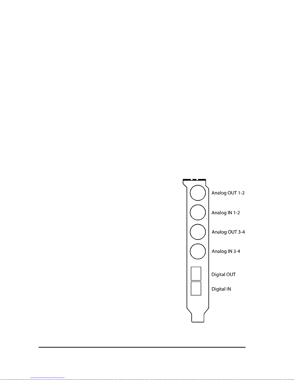
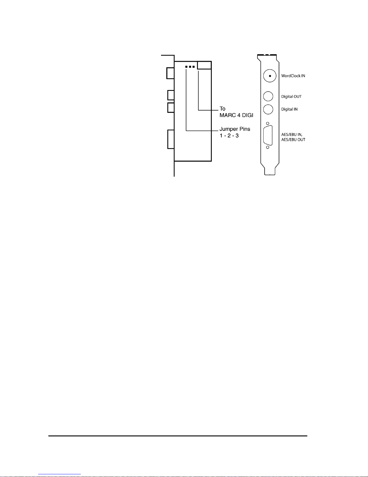
3. Connect the MARC Extender with the MARC 4 Digi by using the
provided flat cable. Please note the illustrations and hints in
Chapter "Ports" on pages 7-8.
4. If you want to use Wordclock synchronisation please refer to
chapter 5.4 first.
5. Screw the MARC Extender on the slot bracket to the case.

4
4. Driver Installation
4.1. About MME, DirectX, ASIO and GSIF
For connecting software and hardware you can use the driver
interfaces MME, DirectX or DirectSound, ASIO and the NemeSys
GigaSampler Interface (GSIF). All these interfaces are provided by the
MARC 4 DIGI driver after it is installed on Windows 95/98/ME. On
Windows NT and Windows 2000 only MME is available. This way you
can use MARC 4 DIGI with all common audio applications. If you use
an ASIO compatible audio software, you will achieve extremely higher
performance of the system as well as shorter latency periods. In an
ideal case 2 ms are possible!
For the MARC Extender no additional driver installation is necessary.
The MARC 4 DIGI driver contains all necessary components and
detects the MARC Extender automatically.
4.2. Windows 95 (Release 950 and 95a)
1. Start your PC after installing your hardware.
2. Windows automatically recognizes at startup the newly installed
device and starts the Hardware Wizard.
3. The "A new hardware component was found" window appears.
4. When selecting the driver which is to be installed, please select
the option “Driver from disk provided by hardware manufacturer”
and confirm your selection.
5. Insert the supplied CD in your CD-ROM drive.
6. Select your CD-ROM drive using the "Browse" button, change to
\marc4d\win9x\english directory and confirm your selection.
Windows copies the driver files and installs MARC 4 DIGI.
7. After finishing the installation, your MARC 4 DIGI is ready to be
operated without having to restart the system.

5
4.3. Windows 95 (Release 95b and 95c)
1. Start your PC after installing your hardware.
2. Windows automatically recognizes at startup the newly installed
device and starts the Hardware Wizard.
3. The "Wizard for device driver updates" appears.
4. Insert the supplied CD in your CD-ROM drive and click "Next".
5. Windows now searches for the updated drivers, but it cannot find
any. Click "Other position" and click "Browse" in the opening
window. Change into the \marc4d\win9x\english directory on the
CD and confirm it by clicking the "OK" button.
6. Windows copies the driver files and installs the MARC 4 DIGI.
During this process you are asked again for the driver's directory.
Select the directory as described previously in step 5.
7. After finishing the installation, your MARC 4 DIGI is ready to be
operated without having to restart the system.
4.4. Windows 98
1. Start your PC after installing your hardware.
2. Windows automatically recognizes at startup the newly installed
device and starts the Hardware Wizard.
3. During the start of Windows the Hardware Wizard searches for
new drivers. Click "Next" to start the search.
4. Enable the “Search for the best driver for your device” option and
confirm by clicking "Next".
5. Insert the supplied CD in your CD-ROM drive.
6. Select your CD-ROM drive in the next dialog, change into the
\marc4d\win9x\english directory and then click "Next". The
Hardware Wizard searches the CD-ROM for the appropriate
drivers and finally displays the names of the drivers.
7. Click "Next”; Windows copies the driver files and installs the
MARC 4 DIGI.
8. After finishing the installation click "Finish”. The driver will be
enabled and the MARC 4 DIGI is ready to be operated without
having to restart the system.

6
4.5. Windows NT 4.0
1. Start your PC after installing your hardware.
2. Log in using administrator rights.
3. Open "System Control" and choose "Multimedia", then change to
the "Devices" tab.
4. Click "Add" button and confirm the opening window by clicking
"OK".
5. Insert the supplied CD in your CD-ROM drive.
6. The "Install driver" window opens. Click "Browse", select your CD-
ROM drive and on the CD-ROM select the \marc4d\nt4\english
directory.
7. Confirm your selection by clicking "OK". Windows shows the
recognized drivers in the “Unlisted or Updated Driver” window.
8. Confirm the window by clicking "OK". The driver files are then
copied.
9. Then the MARC 4 DIGI is available without having to restart the
system.
5. Ports
5.1. External Audio Ports
The picture on the right shows the slot
bracket of your MARC 4 DIGI with its
external audio ports.
For using the analog ports you require 4
shielded cables, which are equipped with a
1/4" TRS plug at the MARC side end. The
plug and/or plugs at the other cable end
depend/s on the ports of the device, which
are to be connected.
If you want to use optical digital ports you
require optical cables, which you can
purchase at your authorised dealer.
When using optical cables, please
ensure that they are free of breaks and
damage, because this may lead to
failures.

7
5.2. Internal Ports
The picture on the right
shows the board of the
MARC 4 DIGI with its
internal ports.
For the processing of
audio signals of your
CD-ROM drive you can
either use an analog
input or an electrical
digital input.
For information which
kind of ports your CD-
ROM drive provides,
please refer to the
appropriate manual.
5.3. SyncBus Connector
If you use several MARC cards or other soundcards developed by
Marian, such as Siena, Prodif 96 PRO or Prodif Plus, you connect the
SyncBus ports of the individual cards using a cable which is available
as accessory. You can purchase a SyncBus cable from Media
Assistance, telephone +49 7946 94 16 80.
The SyncBus of your MARC 4 DIGI has two jobs: on one side it
synchronizes the digital clock and ensures that several cards run
synchronously when they are operated parallel. On the other side it
takes care of the concurrent and sample-accurate starting and stopping
of several internal audio devices. Audio devices in this sense means
either cards with SyncBus or even inputs and outputs of one and the
same card.
For details on the settings see chapter 6.4.1.

8
5.4. Extender
The pictures on the
right show the slot
bracket and the
MARC Extender's
board.
Using the Wordclock
input you can
implement the bond
consisting of MARC 4
DIGI and MARC
Extender in a
Wordclock
environment. If the
extender is connected
at the end of the
Wordclock bus, the
Wordclock input of the extender will have to be terminated. This is
ensured by setting the jumper on the pins 2 to 3 of the jumper block. If
a termination of the Wordclock is not required, you will have to set the
jumper on the pins 1 to 2 of the jumper block.
For details concerning the synchronisation settings, please refer to
chapter 6.4.1.
For the connection of external digital devices with electrical S/PDIF
inputs and outputs you can use commercially available RCA cables.
For the connection of external digital devices with AES/EBU inputs and
outputs you will have to plug the supplied break-out cable on the 9-pin
SUB-D connector. This one will provide you with an XLR socket and an
XLR plug, which you use for connecting your AES/EBU device.

9
6. MARC 4 DIGI-Manager
After successful driver installation the symbol shown on
the right appears for the MARC-Manager in the
Windows taskbar.
You open the MARC-Manager by double-
clicking the taskbar symbol. The dialog box
is displayed on the right.
By enabling the checkboxes "Analog
Inputs", "Digital Inputs", "Analog Outputs",
"Digital Outputs", and "Settings" further
windows are opened, in which you can
read and change the appropriate settings.
By enabling the checkbox "Always on Top"
you can always see the opened windows
on top of all other application windows.
In the "Analog Inputs", "Digital Inputs",
"Analog Outputs" and "Digital Outputs"
windows you have two possibilities to
change the section view of these
windows and hide or unhide the desired
section. You can either use the lowest
section with the checkboxes "Input
Signal" or "Output Signal", "Monitor",
"Level Meter", "Fader", and "Format", or
you right-click the title bar of the window
and enable or disable the hooks in front of the section titles as shown
on the right.
You can hide the section with the checkboxes for the window control by
using the "Show Window Control Area" function.

10
6.1. Analog and Digital Inputs
The settings window for the analog and digital
inputs is divided from the top to the bottom into
the sections "Input Signal", "Monitor" and "Level
Meter".
For analog inputs you can further see the
"Fader" section. Using faders you can adjust the
input level by –40 to +18 dB.
In the "Input Signal" section you determine from
which input the audio signal is processed. For
the analog inputs 3-4 you can additionally to the
external audio ports ("Line") choose the analog
internal CD-ROM input using "CD".
For digital input you can choose
between the digital internal CD-
ROM input ("CD") and "Optical".
"XLR" and "RCA" are
additionally provided only for
connected extenders.
In the "Monitor" section you
determine a situation-dependent
automatic monitoring. For details
please refer to chapter 6.3.
The level meters show the level of
the signals present at the input
between –60 and 0 dB.
The "M" button below the faders is
a mute button. It turns off the
audio signal on the appropriate channel.
The checkbox in the middle below these buttons groups
the faders of the individual channels to stereo groups.

11
6.2. Analog and Digital Outputs
The settings window for the analog outputs is
divided from the top to the bottom into the
"Output Signal", "Level Meter" and "Fader"
sections.
In the "Output Signal" section you determine,
which source signal is played on the output
independently from the situation-dependent
monitor settings. For details please refer to
chapter 6.3.
The level meters show the level of the
determined source signal.
Using the faders you have the possibility to
reduce the output level by up to -60 dB. This has
no effect on the source signal level shown by
the level meters.
The "M" button below the faders turns off the
audio signal on the appropriate channel.
The checkbox in the middle below these buttons
groups the faders of the individual channels to
stereo groups.
The settings window for the
digital outputs is divided from
the top to the bottom into the
"Format", "Output Signal" and
"Level Meter" sections.
Beside the sections of the analog outputs window, you
may perform additional settings for the digital output. In
the "Format" section you determine whether the output
signal will be an AES/EBU or S/PDIF signal.
If you use the MARC Extender together with the MARC
4 DIGI, the AES/EBU output and the S/PDIF RCA
output of the extender always carries the same signal
like the optical output of the MARC 4 DIGI.

12
6.3. Monitor Settings
The three pictures on
the right show possible
settings in the input
windows for situation-
dependent monitoring.
"OnRec"
means, that the signal at the input of the MARC 4 DIGI is switched to
the chosen output only during recording. This way you can check the
signal during recording.
"On Punch"
means, that the signal at the input of the MARC 4 DIGI is switched over
to the output during the period of a punch recording. For this the audio
software needs to provide the PunchIn and PunchOut command for the
driver.
The two pictures on the right show
examples for the monitor setting in the
output windows.
"Play"
means that you can hear the playback
signal of the audio software at the
output of the MARC 4 which uses one
of the determined playback devices of the MARC 4 DIGI. This way
"Play 1-2" in this window equals the "MARC 4 DIGI Analog Playback 1-
2" setting in the audio software.
"Rec"
means that you can hear the signal of the selected input at the output
of the MARC 4.
All these monitor settings are independent from the used audio
software and their settings. Please note that the monitor
capabilities may limit in dependence on clock settings and
number and kind of enabled inputs.

13
6.4. Driver Settings
6.4.1. "Synchronisation" Tab
In this window you perform synchronisation settings for the MARC 4
DIGI.
6.4.1.1. "SyncBus" Section
"Card is Master"
means that the MARC 4 DIGI provides the clock for the SyncBus,
which is responsible for the record and playback sample rate, and
consequently synchronises other cards.
If several cards are to be synchronised using the SyncBus,
exactly one card has to be configured as master. All other cards
have to be configured as slave.
"Internal Clock To SyncBus"
means, that the MARC 4 DIGI transfers the clock signal produced on
the card to the SyncBus.
"Digital Input Clock To SyncBus"
means, that the clock of a device connected to the digital input is
transferred to the SyncBus.

14
6.4.1.2. "Internal Clock" Section
"Default Rate"
This input field contains the frequency at which the internal clock works
provided no device of the card is used by the application. If the card is
configured as master in the SyncBus operation you determine here the
sample rate, which is used by the slave cards as reference provided no
device is used by the master card.
"Word Clock Sync."
If you enable this checkbox the MARC 4 DIGI
synchronises the internal clock to an externally
connected Wordclock and operates as slave. All
devices which were synchronised to the internal
clock before, then depend on the external
Wordclock. The label changes accordingly from
"Internal" to "Internal (Wordclock)".
The "Wordclock Sync" option is only provided
for connected extenders.
6.4.1.3. "Analog 1-2", "Analog 3-4", and "Digital" Sections
Here you can perform separate synchronisation settings for the
according inputs and outputs.
"Internal", "Digital Input" and "SyncBus" are available as clock sources.
In the chapters "Start/Stop Recording" and "Start/Stop Playback" the
following applies:
"Autonomous"
means, that the device does not evaluate any signals on the SyncBus.
It runs in independent operation.
This setting is especially of use, if several audio applications have to
access independently different inputs and outputs.
"SyncBus"
means, that the device evaluates the signals on the SyncBus and
synchronises.
Please note, that for some synchronisation settings the monitor
settings of the driver may be reset.

15
6.4.2. "DirectSound / GSIF" Tab
In this tab you determine the settings for applications which use
DirectSound or NemeSys GigaSampler Interface (GSIF) as driver
interface.
6.4.2.1. "DirectSound" Section
In this section you determine the settings for applications, which use
DirectSound as driver interface.
Here are some information in advance: the ideal settings for the
DirectSound usage depend on some factors in your PC. Because of
this we cannot recommend any ideal settings, but can only provide you
some information on what's behind the possibilities for the settings. You
will have to test yourself, what settings will suit best. Anyway, using the
standard settings will ensure a trouble-free operation.
”Adjust Latency Manually”
Moving the latency control slider changes the size of the audio buffer
on the card. If the settings for the latency period is too low, it may result
in interruptions. In this case you will have to increase the latency
period.

16
"Restrict playback format to:"
When using certain audio programs with DirectSound it may happen,
that the DirectX system attempts to open the driver using a different
sample format, than the audio programs intends to use. This results in
a real time conversion of the signal format by the DirectX system. This
conversion may have negative influence on the sound and system
performance.
If a playback using DirectSound does not sound correct, you will have
to set the signal format, which you use in the audio software. This way
the DirectX system is forced to exclusively open the driver using the set
format in the MARC Manager and the real time conversion is
inapplicable.
”Available Playback Devices limited to:”
Here you adjust the (stereo) output for DirectSound applications, which
have no selection of the output. The output of the audio signals is then
restricted to this (stereo) output.
6.4.2.2. "GigaSampler" Section
We cannot inform you about the ideal settings for GSIF but will explain
to you, what the terms stand for. In order to find the most suitable
settings you will have to test.
"Granularity" and "Latency"
The granularity specifies the size of the audio data blocks, which are
transferred to the hardware by the GigaSampler. The smaller the
latency was set, the smaller will have to be the data blocks, in order to
avoid playback disturbances (granularity: "Fine"). Though the system is
more stressed because of the larger data overhead during the transfer,
the reaction time for the sampler playback is shorter.
Larger data blocks (granularity: "Coarse") stress the system less, but
the reaction time is longer and playback disturbances easier.
For ideal results try to set the values of the two faders as low as
possible.

17
6.4.3. "Misc. / About" Tab
"Disable messages about samplerate conflicts" and "Disable messages
about device conflicts"
Here we provide you with the possibility to display error messages of
clock and sample rate problems as well as device problems. By
standard the display of error messages is suppressed.
We recommend to enable the display only when you meet
problems during the start of the recording or playback, or your
audio software outputs error messages which refer to unknown
external errors.

18
7. ASIO Settings
In the device
control of the ASIO
application you can
see the windows
shown on the right.
By enabling the
checkboxes in front
of the entries of the
inputs and outputs
you can determine
which devices can
be "seen" and be
used by the ASIO
application.
The ASIO
application can see
the devices in the
first "Names
(Aliases)" column.
These names you
can rename as
desired.
The "Execution
Priority" slider
determines in "high" position, that the transmission of ASIO data is
given a higher processor priority, in the position "low" it is given the real
time calculation of PlugIns.
If you activate the device "Marc4d Digital Record" it is essential
that the digital input gets a valid digital signal from an external
digital device. The clock of this digital signal will be used as
reference clock for the whole ASIO setup. If there is no clock
neither record nor playback of any device will work.
Should you use an ASIO compatible audio software, you may
have to perform additional settings in the ASIO configuration of
the software. For details please refer to the software manual.
Table of contents
Other MARIAN Sound Card manuals