Frigidaire PPH2RD Manual

IMPORTANT:
Read this owner information to become familiar with the capabilities and use of your
appliance. Keep this with literature on other appliances where you have easy access to
it in the future. If a problem occurs, check the instructions and follow recommendations
given. If these suggestions don’t eliminate your problem, call your installing contractor or
distributor in your area.
13 SEER
Single Package Heat Pump
USER’s MANUAL & INSTALLATION INSTRUCTIONS
Single Package Heat Pump
INTRODUCTION
Your heat pump is a unique, all weather comfort-
control system appliance. The basic operation
of the heating/cooling system is described
and illustrated on page 1 of this manual. The
surprising fact that heat exists in air even at
below-freezing temperatures is actually the
basic law of physics which the heat pump
uses to provide energy saving heating comfort.
At outdoor temperatures of 47° Fahrenheit
(or 8° Celsius), your heat pump can deliver
approximately 2 to 3 units of heat energy per each
unit of electrical energy used, as compared to a
maximum of only 1 unit of heat energy produced
with conventional heating systems. During the
cooling season, the heat pump reverses the flow
of the heat-absorbing refrigerant to become an
energy-efficient, central air conditioner.

2
SECTION 1. OWNER INFORMATION
Your heat pump will heat and cool your home
year round, saving your energy dollars.During the
summer, a heat pump performs like any normal
air conditioner. That is, the excess heat energy
inside the home is absorbed by the refrigerant
and exhausted outside the home. During the
winter months, a heat pump performs like an
air conditioner run in reverse. That is, available
heat energy outside the home is absorbed by
the refrigerant and exhausted inside the home.
This is an efficient heating means because you
only pay for “moving” the heat from the outdoors
to the indoor area. You do not pay to generate
the heat, as is the case with more traditional
furnace designs.
It is the sole responsibility of the homeowner
to make certain that the heat pump has been
correctly set up and adjusted to operate
properly.
A warranty certificate with full details is included
with the heat pump. However, the manufacturer
will not be responsible for any costs found neces-
sary to correct problems due to improper setup,
improper installation, adjustments, improper op-
erating procedure on the part of the user, etc.
Some specific examples of service calls which
are not included in the limited warranty are:
1. Correcting wiring problems in the electrical
circuit supplying the heat pump.
2. Resetting circuit breakers or other switches.
3. Adjusting or calibrating of thermostat.
To avoid misunderstandings at a later date,
carefully review these responsibilities with your
dealer or service company.
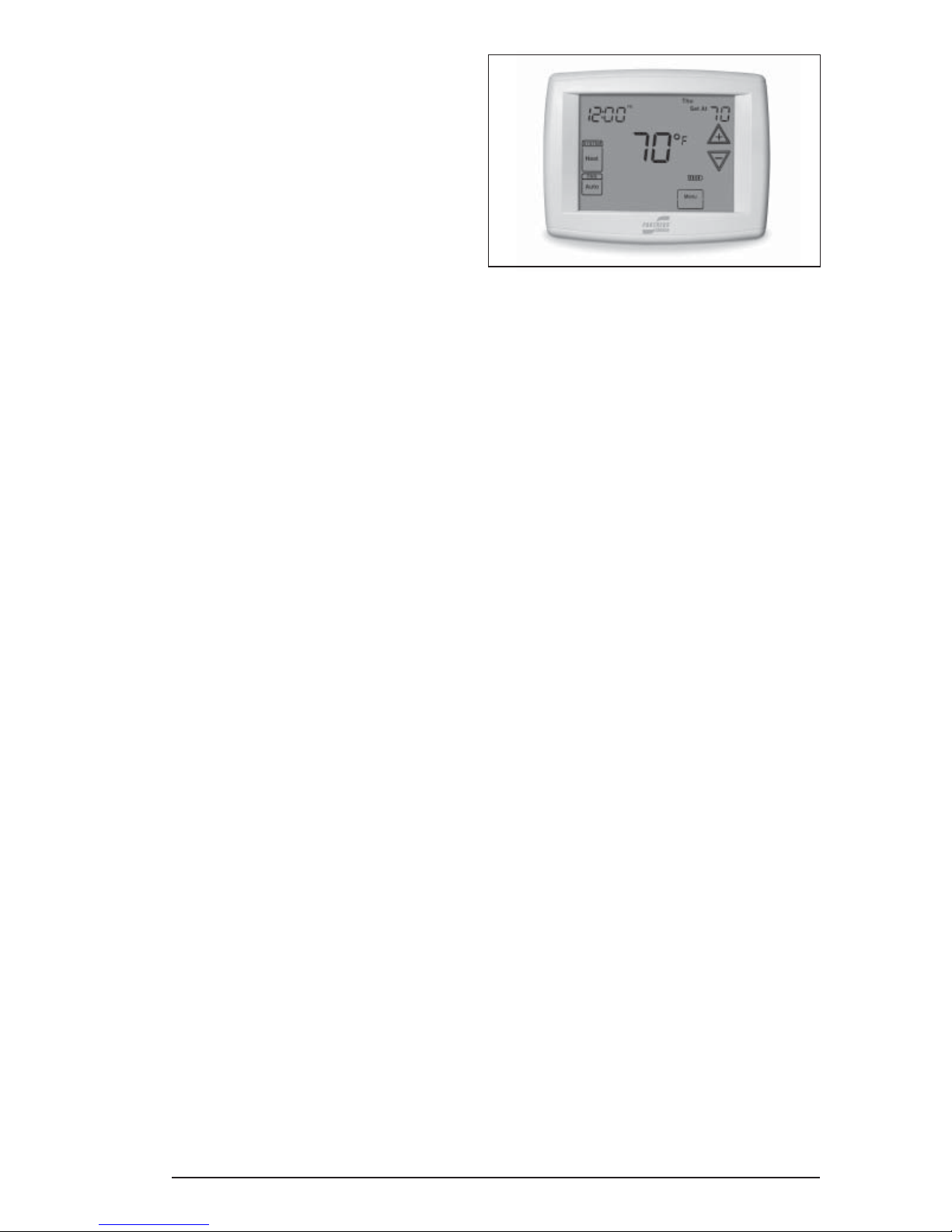
OPERATING INSTRUCTIONS
To Operate Your Heat Pump For Cooling —
1. Set the thermostat system switch to COOL
and the thermostat fan switch to AUTO. (See
Figure 1)
2. Set the thermostat temperature selector to the
desired cooling temperature.The outdoor unit
fan, the indoor blower, and the compressor
will all cycle on and off to maintain the indoor
temperature at the desired cooling level.
NOTE: If the thermostat temperature level is
re-adjusted, or if the thermostat system switch
is re-positioned, the outdoor unit fan and the
compressor may not start immediately. A
protective timer circuit holds the compressor and
the outdoor fan off for approximately five minutes
following a previous operation or the interruption
of the main electric power.
To Operate Your Heat Pump For Heating —
1. Set the thermostat system switch for HEAT
and the thermostat fan switch to AUTO. (See
Figure 1)
2. Set the thermostat temperature selector to the
desired heating temperature.The outdoor unit
fan, the indoor blower, and the compressor
will all cycle on and off to maintain the indoor
temperature at the desired heating level.
NOTE: If the thermostat temperature level is
re-adjusted, or if the thermostat system switch
is re-positioned, the outdoor unit fan and the
compressor may not start immediately. A
protective timer circuit holds the compressor and
the outdoor fan off for approximately five minutes
following a previous operation or the interruption
of the main electrical power.
Emergency Heat — Some thermostats will
include a system switch position termed EM HT
or AUX HT, etc. This is a back-up heating mode
to be used only if there is a suspected problem.
With the system switch set to EM HT, etc., the
compressor and outdoor fan will be locked off and
supplemental heat (electric resistance heating)
will be used as a source of heat. Sustained
use of electric resistance heat in place of the
heat pump will result in an increase in electric
utility costs.
Defrost — During cold weather heating opera-
tion, the outdoor unit will develop a coating of
snow and ice on the heat transfer coil. This is
normal and the unit will periodically defrost itself.
During the defrost cycle, the outdoor fan will stop,
while the compressor continues to run and heat
the outdoor coil, causing the snow and ice to melt.
During defrost, there may be some steam rise
from the outdoor unit as the warm coil causes
some melted frost to evaporate.
Figure 1. Typical Thermostat

3
SECTION 2. INSTALLER INFORMATION
GENERAL
Pressures Within The System — This equip-
ment contains R-410A refrigerant under high
pressure. Installation or servicing should only
be performed by qualified trained personnel
thoroughly familiar with this type equipment.
CAUTION:
This unit uses refrigerant R-410A. DO NOT
under any circumstances use any other re-
frigerant besides R-410A in this unit. Use of
another refrigerant will damage this unit.
Read the following instructions completely
before performing the installation.
These instructions are for the use of qualified
personnel specially trained and experienced
in the installation of this type of equipment
and related system components. Some states
require installation and service personnel to
be licensed. Unqualified individuals should not
attempt to interpret these instructions or install
this equipment.
The single packaged heat pumps are designed
for outdoor installation only and can be readily
connected into the high static duct system of a
home. The only connections needed for instal-
lation are the supply and return ducts, the line
voltage, and thermostat wiring. A complete heat
pump system typically consists of:
• Single Package Heat Pump
• Home Fittings Kit
• Unit Fittings Kit
• Thermostat
CAUTION:
To prevent personal injury and/or
equipment damage, check thermostat
manufacturer’s operation of fan relay
circuit when in EMER HEAT.When the
thermostat system switch is in the
EMER HEAT position, the thermostat
must energize the fan relay when the
fan switch is in the AUTO position.
The single package heat pump is completely
assembled, factory wired, and factory run tested.
The units are ready for easy and immediate
installation.
Use of components other than those speci-
fied may invalidate ARI Certification, Code
Agency Listing, and limited warranty on the air
conditioner.
PRE-INSTALLATION CHECK
Before any installation is attempted, the cool-
ing load of the area to be conditioned must be
calculated and a system of the proper capacity
selected. It is recommended that the area to
be conditioned be completely insulated and
vapor sealed.
The installer should comply with all local codes
and regulations which govern the installation
of this type of equipment. Local codes and
regulations take precedence over any recom-
mendations contained in these instructions.
Consult local building codes and the National
Electrical Code (ANSI CI) for special installation
requirements.
The electrical supply should be checked to de-
termine if adequate power is available. If there
is any question concerning the power supply,
contact the local power company.
Inspecting Equipment: All units are securely
packed at the time of shipment and, upon arrival,
should be carefully inspected for damage.Claims
for damage (apparent or concealed) should be
filed immediately with the carrier.
INSTALLATION
1. SELECT THE BEST LOCATION FOR THE
HEAT PUMP UNIT
IMPORTANT: DO NOT PLACE UNIT UNDER
THE HOME.
• Select a solid, level position, preferably on a
concrete slab, slightly above the grade level,
and parallel to the home.
• The hot condenser air must be discharged
up and away from the home, and if possible,
in a direction with the prevailing wind.
• Do not place the unit in a confined space.
• If practical, place the heat pump where it and
the ducts will be shaded from the afternoon
sun when the heat load is greatest.
• Try to select a site for the unit that is as close
as possible to the proposed return grille
location.
• Keep in mind that the length of the supply and
return ducts should be kept to a minimum with
no sharp radiused bends.

4
2. UNPACK THE UNIT
It is recommended that the unit be unpacked
at the installation site to minimize damage due
to handling.
CAUTION:
Do not tip the unit on its side. Oil may
enter the compressor cylinders and
cause starting trouble. If unit has been
set on its side, restore to upright posi-
tion and do not run for several hours.
Then run unit for a few seconds.Do this
three or four times with five minutes
between runs.
a. Remove the bands from around the unit.
b. Unfold the top and bottom cap flanges.
c. Carefully remove the top cap and tube.
3. CLEARANCES
Minimum clearances, as specified in Figure 2,
MUST by maintained from adjacent structures
to provide room for proper servicing and air
circulation.
Do NOT install unit in a confined or recessed
area that will allow discharge air from the unit to
re-circulate into the condenser air inlet, through
the coil.
Service Access Clearance:
Blower access panel side .......................... 24”
Electrical compartment access panel side ... 12”
Clearance between overhang and top of
unit .........................................................72”
Clearance around condenser coil area to wall
or shrubs (excludes duct panel side).......... 12”
Minimum clearance to combustible materials:
Combustible Base (Wood or Class A, B, or C
roof Covering material) ...............................0”
Supply and Return Air Ducts.......................0”
Duct Connection side..................................0”
DUCT REQUIREMENTS
The supply duct system, including the number
and type of registers, will have much more ef-
fect on the performance of an air conditioning
system then any other factor. The duct must be
sufficiently large to conduct an adequate amount
of air to each register.
4. INSTALL THE RETURN AND SUPPLY AIR
FITTINGS ON THE UNIT
The supply and return fittings are included with
select models. If supplied, the duct fittings are
shipped in the supply duct.They attach to the unit
openings with a flange and bead arrangement,
secured with two sheet metal screws. Note: For
ease of access, install fitting before positioning
unit in final location.
Figure 3. Return and Supply Air Fittings
Supply Air
14” Duct Dimples
Return Air
Transition Duct Screws
13 SEER Return Dia. (in)
2 Ton 12
2 1/2 Ton 14
3 Ton 14
3 1/2 Ton 14
4 Ton 14
5 Ton 14
6 ft.
24"
12"
12"
Figure 2. Minimum Unit Clearances

5
Figure 4. Return Air Box
SUPPLY DUCT
Position the supply duct collar, if supplied, so the
edge of the unit opening fits between the flange
and the bead.Overlap the collar ends keeping the
small screw holes underneath. Align the holes in
the crimped area and install one screw.
Note: It may be necessary to loosen the four
screws that hold the transition duct in order to
install the supply fitting. Re-tighten when instal-
lation is complete.
Tap collar as necessary to ensure engagement
with unit opening and install second screw.
Tighten first screw. Rotate collar clockwise so
joint is near three o’clock position.
RETURN DUCT
The 12” return duct is installed in the same
manner as the supply duct. If the duct has a 14”
return, follow these instructions.
Align the slots with the holes in the collar and
install two screws. Position the collar over the
opening and align the four notches in the collar
with the four dimples in the panel. Using self-
drilling screws (10-16x.5) attach the collar to the
rear panel. On some models a 14” duct collar is
provided for the return duct.
5. LOCATING AND INSTALLING THE
RETURN AIR ASSEMBLY
To avoid complications, locate and install the
return air assembly first. The return air box with
grille and filter (Figure 4) should not be located
in heavy traffic areas like hallways or center of
rooms.A good spot is in a corner or under a table,
if a minimum two inch clearance is available.
If desired, the return opening can be located
inside a closet with louvered doors that have
an open area equal to or greater than the 12” x
20” grille furnished. The return air grille can be
placed in the wall of a closet and the air ducted
into the filter box through a boxed-in area at the
closet floor level. Make sure the filter is readily
accessible.
After determining the location of the return air
opening, start the installation from under the
home by cutting a small hole in the fiber under-
board to determine how the floor joist location
will affect cutting the opening needed for the box.
Floor joists generally are located on 16” centers,
leaving 14-3/8” between joists. After measuring
the return air box (approximately 12-1/4” x 20-
1/4”), cut the hole through the floor so that the
box will fit between the floor joists. Care should
be taken when cutting through carpeting to avoid
snags.In most installations it will be necessary to
cut a similar hole in the fiberboard directly under
the hole in the floor. However, if the floor is more
than ten inches deep, it will only be necessary
to cut a hole for the collar on the return air box
or for the insulated duct.
Set the box into the opening and fasten with
screws or nails. Put the filter and return air
grille in place.
6. LOCATING AND INSTALLING THE
SUPPLY DAMPER(S)
When locating the supply damper(s), carefully
check floor joists and frame members that could
interfere with the installation of the damper
or flexible duct. Ideally, the damper should be
located in the bottom of the main duct, forward
of center of the home, at least three feet from
the nearest register. The round supply opening
in the slanted side of the damper should face
the side of the home where the heat pump is
located. To locate the center of the heat duct,
first cut a small hole in the fiberboard below the
duct at the desired location. After locating the
duct center, cut a hole approximately 3/4” larger
than the damper opening in the fiberboard. Cut
a 9-1/8” x 13-1/8” hole in the duct and bend over
Figure 5. Supply Damper
AUTOMATIC DAMPER IS CLOSED
WHEN HEAT PUMP IS OFF

6
all tabs flat on the inside of the heat duct. After
inserting the damper into the duct, bend over all
tabs flat on the inside of the heat duct. Seal the
opening between the fiberboard and damper or
flexible duct.
DUCTING SYSTEM
DUCT REQUIREMENTS
The supply duct system, including the number
and type of registers, will have much more
effect on the performance of the system than
any other factor. The duct must be sufficiently
large to conduct an adequate amount of air to
each register.
Air ducts should be installed in accordance
with the standards of the National Fire Protec-
tion Association “Standard for Installation of Air
Conditioning and Ventilation Systems” (NFPA
90A), “Standard for Installation of Residence
Type Warm Air Heating and Air Conditioning
Systems” (NFPA 90B), these instructions, and
all applicable codes.
TYPICAL APPLICATIONS
Figure 6. Drain Trap
Elbow
P-Trap
MULTIPLE DUCT APPLICATIONSINGLE DUCT APPLICATION
6
6
4
4
5
2
3
1
5
2
36
4
1
7
1
3
2
4
5
6
7
Figure 7. Typical Applications
Note: For highly resistive duct systems it may
be necessary to add an additional return air duct
and or supply to achieve maximum performance
and prevent coil icing and refrigerant flood
back.
Ref. No. Description
12” x 20” Return Air
16” x 20” Air Filter
12” x 20” Grille
Supply Damper
12” or 14” Diameter Flex Return Duct
12” Diameter Flex Supply Duct
12” x 12” x 12” “Y” Fitting

7
Figure 8. Motor Lead Connection
THE HEAT PUMP SYSTEM WILL NOT COOL
OR HEAT THE HOME IF THE AIR IS LOST
TO THE OUTSIDE THROUGH LEAKS IN THE
DUCT SYSTEM. ALSO, DUCTS WHICH ARE
COLLAPSED OR RESTRICTED BY FOREIGN
OBJECTS WILL PREVENT ADEQUATE AIR
FLOW.
CONNECTING THE RETURN AND SUPPLY
AIR FLEXIBLE DUCTS
The return duct may be 12” or 14” diameter de-
pending on unit size. (See Table on page 5)
a. The supply duct for all units is twelve inches
in diameter.
b. The flexible ducts can be connected to the
corresponding fittings with the clamps pro-
vided with the ducts. Note: All connections
should be leak tight or a loss in cooling
capacity will result.
c. The flexible ducts may be cut to the required
length, see instructions packed with duct.
Keep all ducts as short and straight as
possible. Avoid sharp bends.
d. Ducts may be spliced with sheet metal
sleeves and clamps.(See Ducting Installation
Accessories page 6.)
e. Once the inner duct is connected to the
proper fitting, the insulation and plastic sleeve
should be pulled over the connection and
clamped.
f. For homes with multiple supply ducts or for
special applications, a Y fitting is available to
divide the supply air so it can be ducted to
different areas of the home for more efficient
cooling.Note: TheY fitting should be insulated
for maximum performance.
Blower Speed For optimum system performance
and comfort, it may be necessary to change
the factory set speed. See Figure 8 for factory
settings. NOTE: The 2 Ton blower motor has
three speed taps, Low, Med, High. The 2.5 ton
standard blower motor has two speeds, Low and
High. The 3, 3.5 and 4 ton models have High
Efficiency Motors with 5 speed taps.
If Standard Motor (2 and 2.5 Ton)
1. Disconnect all electrical power to the unit
and remove the service panel.
2. The blower speed is preset at the factory
for operation at the same speed for
heating and cooling.
3. Place the desired blower speed lead on
the “COM” terminal of the blower relay.
Use another wire tie (field supplied) to
bundle the remaining motor lead up and
out of the way.
If High Efficiency Motor (3, 3.5, and 4 Ton)
1. Disconnect all electrical power to the unit
and remove the service panel.
2. Locate the orange and red wires
terminated to the blower motor. The
orange wire controls the cooling
operation and the red wire controls the
heating operation.
3. Verify the required speed from the airflow
data found in Figure 8.Place appropriate
wire on the appropriate motor speed tap
for the required airflow.
CAUTION:
To avoid personal injury or property
damage, make certain that the motor
leads cannot come into contact with
any uninsulated metal components
of the unit.
Check all factory wiring per the unit wiring
diagram and inspect the factory wiring connec-
tions to be sure none loosened during shipping
or installation.
* Denotes Factory Set Cooling Speed
** Denotes Factory Set Electric Heating Speed
† Denotes Factory Set Cooling and Electric Heating Speed
Model Q5RD Wire Color /
Speed Tap Motor Speed Air Flow
(0.3 In. WC)
024K T6 Low 490
Black/T5 Med †802
T4 High 1133
030K Red Low 770
Black High †1064
036K
T1 Low 750
Red/T2 Med/Low ** 1000
Orange/T3 Medium * 1140
T4 Medium/High 1300
T5 High 1450
042K
T1 Low 1340
Orange/T2 Med/Low * 1450
Red/T3 Medium ** 1500
T4 Medium/High 1650
T5 High 1970
048K
T1 Low 1340
Red/T2 Med/Low ** 1450
Orange/T3 Medium * 1500
T4 Medium/High 1650
T5 High 1970
060K
T1 Low 1300
T2 Med/Low 1400
T3 Medium** 1500
T4 Medium/High* 1650
T5 High 1950

8
CONDENSATE DRAIN
A 3/4” condensate fitting extends out of the side
of the unit.The drain trap, shipped in the electrical
compartment, must be installed to prevent water
from collecting inside the unit.Thread the elbow
provided with the unit into the drain connection
until hand tight. Install the trap into the fitting
making sure it is level. Route the condensate
from the trap to a suitable drain. Any tubing or
hose connected must have the outlet below trap
level for proper drainage.
WARNING:
Turn off electrical power before servic-
ing controls. Severe electrical shock
may result unless power is turned off.
Unit must be installed in compliance
with the National Electrical Code (NEC)
and local codes.
ELECTRICAL CONNECTIONS
1. ELECTRICAL SERVICE
High Voltage
a. Install a branch circuit disconnect of adequate
size per NEC. Locate the disconnect within
sight of the unit.
b. Extend leads through power wiring hole
provided. Connect L1 and L2 directly to the
contactor. (See Figure 9.)
c. Ground the heat pump unit using the green
grounding screw provided in the control
panel.
Low Voltage
a. Route 24v control wires through the sealing
grommet near the power entrance. (See
Figure 9.)
b. Connect the control wires to the defrost board
and blower relay wire. (See Figure 10.)
2. OVERCURRENT PROTECTION
In general, the best fuse or breaker for any
heat pump is the smallest size that will permit
the equipment to run under normal use and
service without nuisance trips. Such a device,
sized properly, gives maximum equipment
protection. The principal reason for specifying
atime delay type is to prevent nuisance trips
when the unit starts.
In the event that a fuse does blow or a breaker
trips, always determine the reason. Do not arbi-
trarily put in a larger fuse or breaker and do not,
in any case, exceed the maximum size listed on
the data label of the unit.
3. LOCATING THE THERMOSTAT
Locate the thermostat away from drafts and
slamming doors and place it where there is a free
flow of air.Mount on an inside wall approximately
five feet from the floor.
Do not locate near a lamp, kitchen range, direct
sunlight, or in line with air flow from supply
registers.
Connect the Heat-Cool Thermostat: The
heat-cool thermostat is equipped with a system
HEAT-COOL switch, which provides a positive
means of preventing simultaneous operation of
the heating and cooling units.The thermostat is
also equipped with an ON-AUTO fan switch which
allows the home owner to operate the indoor
blower when air circulation is desired.
Connect the low voltage wires to the respective
terminals on the thermostat base. See thermo-
stat instruction sheet for more detailed informa-
tion. (See Figure 10).
Figure 9. Power Entry
Low Voltage
High Voltage

9
Typical Wiring (Field Supplied) for 1-Stage Cool, 1 Stage Electric Heat
Typical Wiring (Field Supplied) for 1-Stage Cool, 2-Stage Electric Heat
with an Optional Outdoor Thermostat
Figure 10. Typical Heat Pump Thermostat Connections
E
O
G
R
Y1
INDOOR
THERMOSTAT
SUB-BASE
Green
W2
C
DEFROST
BOARD
1
2
3
4
5
6
7
8
9
Brown
Orange
Accessory Heat Plug
Optional 2nd Stage
Outdoor Thermostat
(Field Supplied)
Outdoor Thermostat
(Factory Option)
E
O
G
R
Y1
INDOOR
THERMOSTAT
SUB-BASE
Green
W2
C
DEFROST
BOARD
1
2
3
4
5
6
7
8
9
Brown
Orange
Accessory Heat Plug
Outdoor
Thermostat
(Factory Option)

10
If two stage heating is desired, an optional
2nd stage outdoor thermostat may be
installed:Connect the thermostat to the orange
low voltage wire and the E terminal on the
defrost board (See Figure 10 page 9). See the
thermostat instructions for details on setting
the outdoor thermostat.
4. DEFROST CYCLE CONTROL
The defrost cycle is initiated via a signal from
the defrost sensor on the outdoor coil to the
defrost control board inside the control panel
indicating the coil temperature is low enough
to start accumulating frost. The board has
interval settings of 30 minutes, 60 minutes, and
90 minutes. These time intervals represent the
time elapsed before defrosting cycle starts and
they are dependent on the climate conditions
of the installation. A 30 minute setting would
be recommended in a moist climate such as
Seattle, Washington. A 90 minute setting would
be adequate in a dry climate such as southern
Arizona. The factory time interval setting is 30
minutes.
5. OUTDOOR THERMOSTAT (Factory Option)
The outdoor thermostat prevents the electrical
auxiliary heat (if used) from operating above
a desired set point. The factory temperature
setting is at 40°F.
6. ELECTRIC HEAT PACKAGE (OPTIONAL)
The heat pumps are shipped without an
auxiliary electric heat kit installed. If electric
heat is desired, an accessory Heater Kit must
be field installed. See Specifications Sheet for
available kits and their application.
• Select the correct size heat package for the
installation.
• Follow installation instructions provided with
each heater kit.
• Installation is most easily accomplished before
making duct or electrical connections.
• Refer to figure 8 for blower speeds.
SYSTEM OPERATION
1. PRE-START CHECK LIST
The following check list should be observed prior
to starting the unit.
Is the unit level? It should be level or slightly
slanted toward the drain for proper conden-
sate drainage.
Is the unit installed with the proper clear-
ances (See Figure 2)?
Is the wiring correct according to the wiring
diagram and electrical codes?
Are all the wiring connections tight? Check
the condenser fan to make sure it turns
freely.
Is the overcurrent protection properly
sized?
Is the thermostat wired correctly? Is it
installed in a proper location?
2. START-UP PROCEDURE
The control circuit consists of an anti-short cycle
timer that will not let compressor re-start before
five (5) minutes have elapsed.
Set the thermostat system switch to OFF, and
the thermostat fan switch to AUTO. Apply power
at the disconnect switch and check the system
operations:
a. Air Circulation — Leave the thermostat
system switch at OFF, and set the thermostat
fan switch to ON. Blower should run
continuously. Check the air delivery at the
supply registers and adjust register openings
for balanced air distribution. Examine
ductwork for leaks or obstruction if insufficient
air is detected.
Set the thermostat fan switch to AUTO;the blower
should stop running.
b. System Heating — Set the thermostat
system switch to HEAT and set the thermostat
fan switch to AUTO. Position the thermostat
temperature selector above the existing room
temperature and check for the discharge of
warm air at the supply registers.
c. System Cooling — Set the thermostat
system switch to COOL and set the thermostat
fan switch to AUTO. Position the thermostat
temperature selector below the existing room
temperature. Allow the cooling system to
operate for several minutes and check for the
discharge of cool air at the supply registers.
d. Short cycle protection — The control
circuit is equipped with a time-delay feature
for protection against short cycling. With
the system operating in the cooling mode,
gradually raise the thermostat temperature
setting until the whole system de-energizes.
Immediately lower the thermostat temperature
to the original setting and verify that the indoor
blower is energized. After approximately 5
minutes the compressor and the outdoor fan
will energize.

11
e. Emergency Heat — (Available only when
Electric heat is supplied) Set the thermostat
system switch to EM HT and set the thermostat
fan switch to either AUTO (intermittent air) or
to ON (continuous air). Position the thermostat
temperature selector above the existing room
temperature and check the following:
1. The thermostat auxiliary heat light
(RED) should be on.
2. The heat pump compressor and the
fan should not run; low voltage circuit
remains energized.
3. The blower will run according to the
thermostat fan switch setting.
Refrigerant Charging — Packaged Air
Conditioners are fully charged with R410-A
refrigerant at the factory. The system refrigerant
charge can be checked and adjusted by removing
the compressor cover panel and attaching gauge
lines which have a “schrader” depression device
present to activate the valve. Draw a vacuum
on gauge lines to remove air before attaching
them to the service ports on the unit. Refrigerant
charging must be done by qualified personnel
familiar with safe and environmentally responsible
refrigerant handling procedures.
DEFROST CONTROL BOARD OPERATION
AND TESTING
1. Terminals “R”-”C” must have 24±V present
between them in order for the time delay and
defrost sequences to be operational.
2. Jumper the “T2”-”DFT” test pins. This will
indicate to the board that the defrost T-stat
is closed(if the compressor is running).
Defrost T-stat is closed at 32° or below and
is open at 68° or above. But it’s state is
unknown if the temperature is between 32°F
and 68°F. The defrost thermostat tells the
board whether a defrost cycle needs to be
started or terminated. With the DFT closed
the unit will run for 30/60/90 minutes in heat
mode and then defrost the outdoor coil. The
defrost will turn off the outdoor fan, turn on the
compressor and raise the coil temperature to
68°F. This will open the DFT and terminate
the defrost. If the DFT does not open the
defrost will end after 10 minutes.
3. Defrost board speed-up. With compressor
running in heat mode, next jump the “Test”
pin to “C” on terminal strip. This will initiate
a defrost test in 5, 10 or 15 seconds (This
is determined by the 30, 60 or 90 minute
defrost pin settings. The factory setting will
be 30 minutes). Note that this will bypass the
compressor off delay when the unit goes into
defrost test and if left in defrost test, the delay
will be bypassed when the test is terminated
by the processor. If the jumper is removed
before the test is over the processor will
perform the remainder of a normal defrost.
See step 2 above.
4. Remove the jumpers.
Note:Thedelay/no-delaypinconcernscompressor
operation during defrosts. The default setting is
delay. Reciprocating compressors should only
use this setting in conjunction with an approved
hard start kit.Scroll compressors that have noise
issues while going into or coming out of defrost
should use this 30 second delay to reduce the
defrost noise. To switch from no-delay to delay
remove the pin from the “no-delay” pin location
and shift it to the “delay” pin location.
Speed up changes:
Manually initiating a defrost will cause the
compressor to run continually when entering
defrost.
Normal defrost operation:
To test normal defrost operation when the
temperature is above 35°F, jumper “R” to
“DFT”on the 624656 board and allow the unit
to run for 30 minutes. Defrost will continue
until the “R” to “DFT” jumper is removed or
for 10 minutes. Remove the jumper.
The 5 minute time delay feature can be shortened
1 time to 1 second by jumping the “Test” to “C”
terminal. Remove the jumper and repeat as
desired.
Note: If jumper is left on the “Test” to “common”
pins permanently, the defrost cycle will become
inoperable.
Defrost Test Procedure for 624656
1. Jumper “T2” to “DFT” at the test terminals.
2. With unit running in heat mode, short the
“TEST”terminal to the common terminal near
it. This will speed up the board and cause
it to enter defrost mode in 5/10/15 seconds
depending on the defrost time selection.
Compressor delay will not function during
speed-up.
3. This test will end in 5 seconds if the “TEST”-
common short is not removed.
4. Remove both the short and the “T2” to “DFT”
jumper to terminate the defrost cycle. The
30 second compressor delay should operate
normally.
5. Test is complete, reset thermostat to home
owner preference.

12
13 SEER - Refrigerant Charging Tables for Cooling Mode of Operation
2
To n
OUTDOOR TEMPERATURE (°F)
70 75 80 85 90 95 100 105
Suct.
Press.
Liq.
Press.
Dis.
Temp.
Liq.
Press.
Dis.
Temp.
Liq.
Press.
Dis.
Temp.
Liq.
Press.
Dis.
Temp.
Liq.
Press.
Dis.
Temp.
Liq.
Press.
Dis.
Temp.
Liq.
Press.
Dis.
Temp.
Liq.
Press.
Dis.
Temp.
136 260 136
138 262 142 283 140
140 265 147 285 145 306 143
142 270 146 288 150 309 148 330 147
144 274 148 293 150 311 153 332 152 353 151
146 296 154 315 155 334 156 355 155 376 155
148 319 158 338 159 357 160 378 159 399 159
150 342 163 361 163 380 163 401 163 422 163
152 345 167 364 167 383 167 403 167 424 167
154 368 171 387 171 406 171 426 170
156 390 175 410 175 429 175
158 413 179 432 179
160 436 183
162
*
Note: All pressures are listed in psig. and all temperatures in °F.
- Shaded Boxes indicate flooded conditions
- Rated Design Values. Suction Pressure will be lower than design
value if indoor air flow, entering dry bulb, or entering wet bulb
temperatures are lower than design.
- Discharge temperatures greater than charted values indicate an
undercharged system.
Refrigerant Charging Chart Legend for Cooling Mode of Operation
2.5
To n
OUTDOOR TEMPERATURE (°F)
70 75 80 85 90 95 100 105
Suct.
Press.
Liq.
Press.
Dis.
Temp.
Liq.
Press.
Dis.
Temp.
Liq.
Press.
Dis.
Temp.
Liq.
Press.
Dis.
Temp.
Liq.
Press.
Dis.
Temp.
Liq.
Press.
Dis.
Temp.
Liq.
Press.
Dis.
Temp.
Liq.
Press.
Dis.
Temp.
139 258 115
141 260 121 281 121
143 262 126 283 126 304 126
145 266 129 285 131 306 131 327 132
147 269 131 289 134 308 136 329 136 350 137
149 292 137 312 139 331 141 352 142 373 143
151 315 143 334 145 354 146 375 147 396 148
153 338 148 357 150 377 151 398 152 419 154
155 341 152 361 154 380 155 400 156 421 157
157 364 158 384 159 403 161 423 161
159 387 163 407 165 426 166
161 410 169 430 170
163 433 175
165

13
13 SEER - Refrigerant Charging Tables
for Cooling Mode of Operation Continued
3.5
To n
OUTDOOR TEMPERATURE (°F)
70 75 80 85 90 95 100 105
Suct.
Press.
Liq.
Press.
Dis.
Temp.
Liq.
Press.
Dis.
Temp.
Liq.
Press.
Dis.
Temp.
Liq.
Press.
Dis.
Temp.
Liq.
Press.
Dis.
Temp.
Liq.
Press.
Dis.
Temp.
Liq.
Press.
Dis.
Temp.
Liq.
Press.
Dis.
Temp.
134 269 129
136 271 135 293 134
138 274 140 295 139 316 138
140 279 139 297 144 318 143 340 143
142 282 142 302 145 320 148 342 148 363 148
144 305 148 325 150 344 152 365 152 387 153
146 328 154 348 155 367 156 389 157 410 157
148 351 159 371 160 391 161 412 161 434 162
150 355 163 374 164 394 165 414 165 436 166
152 378 168 398 169 417 170 438 170
154 401 173 421 174 440 174
156 424 178 444 179
158 447 183
160
3
To n
OUTDOOR TEMPERATURE (°F)
70 75 80 85 90 95 100 105
Suct.
Press.
Liq.
Press.
Dis.
Temp.
Liq.
Press.
Dis.
Temp.
Liq.
Press.
Dis.
Temp.
Liq.
Press.
Dis.
Temp.
Liq.
Press.
Dis.
Temp.
Liq.
Press.
Dis.
Temp.
Liq.
Press.
Dis.
Temp.
Liq.
Press.
Dis.
Temp.
138 267 113
140 269 118 290 119
142 271 123 292 124 314 125
144 272 131 294 129 316 130 337 131
146 276 133 296 135 318 135 339 136 360 137
148 300 138 320 140 341 141 362 142 384 143
150 323 143 344 145 364 146 386 147 407 148
152 347 148 367 150 388 151 409 152 430 154
154 351 152 371 154 391 155 411 156 432 157
156 374 158 395 159 415 161 434 161
158 398 163 418 165 439 166
160 422 169 442 171
162 445 175
164

14
13 SEER - Refrigerant Charging Tables
for Cooling Mode of Operation Continued
4
To n
OUTDOOR TEMPERATURE (°F)
70 75 80 85 90 95 100 105
Suct.
Press.
Liq.
Press.
Dis.
Temp.
Liq.
Press.
Dis.
Temp.
Liq.
Press.
Dis.
Temp.
Liq.
Press.
Dis.
Temp.
Liq.
Press.
Dis.
Temp.
Liq.
Press.
Dis.
Temp.
Liq.
Press.
Dis.
Temp.
Liq.
Press.
Dis.
Temp.
133 280 143
135 282 149 305 147
137 285 154 307 152 330 151
139 290 153 309 157 332 156 355 155
141 293 156 314 158 334 160 357 159 380 158
143 318 161 339 163 359 164 382 163 405 163
145 342 166 363 167 384 167 407 167 430 167
147 367 170 388 171 409 171 432 171 455 171
149 370 174 391 175 412 175 434 175 457 175
151 395 179 416 179 437 179 459 178
153 419 183 440 183 461 183
155 444 187 465 187
157 468 191
159
5 Ton OUTDOOR TEMPERATURE ( deg. F )
70 75 80 85 90 95 100 105
Suc.
Press.
Liq.
Press.
Dis.
Temp.
Liq.
Press.
Dis.
Temp.
Liq.
Press.
Dis.
Temp.
Liq.
Press.
Dis.
Temp.
Liq.
Press.
Dis.
Temp.
Liq.
Press.
Dis.
Temp.
Liq.
Press.
Dis.
Temp.
Liq.
Press.
Dis.
Temp.
124
126 274 101
128 276 112 295 111
130 277 124 298 121 318 119
132 279 129 300 131 320 128 340 128 360 130
134 280 146 303 136 326 128 344 134 363 137 383 136
136 304 150 327 141 350 133 367 145 387 142 406 141
138 329 155 352 145 374 145 391 149 410 148 430 148
140 354 159 376 153 398 148 415 154 434 153
142 378 164 401 158 423 153 439 159
144 403 168 425 163 447 158
146 428 172 450 167
148 452 176
150

15
2 Ton OUTDOOR TEMPERATURE (DEG. F)
0102030405060
Suc. Liquid Disch. Suc. Liquid Disch. Suc. Liquid Disch. Suc. Liquid Disch. Suc. Liquid Disch. Suc. Liquid Disch. Suc. Liquid Disch.
Press Press. Temp. Press. Press. Temp. Press. Press. Temp. Press. Press. Temp. Press. Press. Temp. Press. Press. Temp. Press. Press. Temp.
37 209 114 51 232 121 65 254 127 78 277 133 94 292 142 110 322 154 127 353 165
38 216 112 52 238 119 66 259 125 79 281 131 95 299 140 111 329 149 128 360 159
39 223 110 53 244 117 67 264 123 80 284 129 96 306 137 112 336 145 129 367 153
40 230 108 54 250 115 68 269 121 81 288 127 97 313 134 113 343 140 130 374 147
41 237 106 55 255 113 69 274 119 82 292 125 98 320 131 114 350 136 131 381 140
42 244 104 56 261 111 70 278 117 83 295 123 99 327 128 115 357 131 132 388 134
43 251 102 57 267 109 71 283 115 84 299 121 100 334 125 116 364 127 133 395 128
13 SEER - Refrigerant Charging Tables
for Heating Mode of Operation
2.5
Ton OUTDOOR TEMPERATURE (DEG. F)
0102030405060
Suc. Liquid Disch. Suc. Liquid Disch. Suc. Liquid Disch. Suc. Liquid Disch. Suc. Liquid Disch. Suc. Liquid Disch. Suc. Liquid Disch.
Press Press. Temp. Press. Press. Temp. Press. Press. Temp. Press. Press. Temp. Press. Press. Temp. Press. Press. Temp. Press. Press. Temp.
47 226 137 55 235 134 62 245 130 69 254 126 85 260 131 109 286 143 134 313 155
48 233 135 56 241 132 63 250 128 70 258 124 86 267 128 110 293 138 135 320 149
49 240 133 57 247 130 64 254 126 71 262 122 87 274 125 111 300 134 136 327 143
50 247 131 58 253 128 65 259 124 72 265 120 88 281 122 112 307 129 137 334 137
51 254 129 59 259 126 66 264 122 73 269 118 89 288 119 113 314 125 138 341 130
52 261 127 60 265 124 67 269 120 74 273 116 90 295 117 114 321 120 139 348 124
53 268 125 61 271 122 68 274 118 75 276 114 91 302 114 115 328 116 140 355 118

16
13 SEER - Refrigerant Charging Tables
for Heating Mode of Operation (continued)
3.5 Ton OUTDOOR TEMPERATURE (DEG. F)
0 102030405060
Suc. Liquid Disch. Suc. Liquid Disch. Suc. Liquid Disch. Suc. Liquid Disch. Suc. Liquid Disch. Suc. Liquid Disch. Suc. Liquid Disch.
Press Press. Temp. Press. Press. Temp. Press. Press. Temp. Press. Press. Temp. Press. Press. Temp. Press. Press. Temp. Press. Press. Temp.
33 217 136 48 239 137 63 261 138 78 283 139 92 295 144 107 319 154 121 343 163
34 224 134 49 245 135 64 266 136 79 287 137 93 302 141 108 326 149 122 350 157
35 231 132 50 251 133 65 271 134 80 290 135 94 309 139 109 333 145 123 357 151
36 238 130 51 257 131 66 275 132 81 294 133 95 316 136 110 340 140 124 364 145
37 245 128 52 262 129 67 280 130 82 298 131 96 323 133 111 347 136 125 371 139
38 252 126 53 268 127 68 285 128 83 301 129 97 330 130 112 354 131 126 378 133
39 259 124 54 274 125 69 290 126 84 305 127 98 337 127 113 361 127 127 385 126
3 Ton OUTDOOR TEMPERATURE (DEG. F)
0102030405060
Suc. Liquid Disch. Suc. Liquid Disch. Suc. Liquid Disch. Suc. Liquid Disch. Suc. Liquid Disch. Suc. Liquid Disch. Suc. Liquid Disch.
Press Press. Temp. Press. Press. Temp. Press. Press. Temp. Press. Press. Temp. Press. Press. Temp. Press. Press. Temp. Press. Press. Temp.
34 216 127 49 234 128 63 251 129 78 269 130 93 275 135 109 294 145 124 313 154
35 223 125 50 240 126 64 256 127 79 272 128 94 282 133 110 301 140 125 320 148
36 230 123 51 246 124 65 261 125 80 276 126 95 289 130 111 308 136 126 327 142
37 237 121 52 251 122 66 266 123 81 280 124 96 296 127 112 315 131 127 334 136
38 244 119 53 257 120 67 270 121 82 283 122 97 303 124 113 322 127 128 341 129
39 251 117 54 263 118 68 275 119 83 287 120 98 310 121 114 329 122 129 348 123
40 258 115 55 269 116 69 280 117 84 291 118 99 317 118 115 336 118 130 355 117

17
13 SEER - Refrigerant Charging Tables
for Heating Mode of Operation (continued)
4 Ton OUTDOOR TEMPERATURE (DEG. F)
0 102030405060
Suc. Liquid Disch. Suc. Liquid Disch. Suc. Liquid Disch. Suc. Liquid Disch. Suc. Liquid Disch. Suc. Liquid Disch. Suc. Liquid Disch.
Press Press. Temp. Press. Press. Temp. Press. Press. Temp. Press. Press. Temp. Press. Press. Temp. Press. Press. Temp. Press. Press. Temp.
33 218 127 46 236 129 59 254 131 72 272 133 87 285 139 105 315 148 122 346 158
34 225 125 47 242 127 60 259 129 73 276 131 88 292 136 106 322 144 123 353 151
35 232 123 48 248 125 61 264 127 74 279 129 89 299 133 107 329 139 124 360 145
36 239 121 49 254 123 62 268 125 75 283 127 90 306 131 108 336 135 125 367 139
37 246 119 50 259 121 63 273 123 76 287 125 91 313 128 109 343 130 126 374 133
38 253 117 51 265 119 64 278 121 77 290 123 92 320 125 110 350 126 127 381 127
39 260 115 52 271 117 65 283 119 78 294 121 93 327 122 111 357 121 128 388 121
5 Ton OUTDOOR TEMPERATURE (DEG. F)
0 102030405060
Suc.
Press
Liquid
Press.
Disch.
Temp.
Suc.
Press.
Liquid
Press.
Disch.
Temp.
Suc.
Press.
Liquid
Press.
Disch.
Temp.
Suc.
Press.
Liquid
Press.
Disch.
Temp.
Suc.
Press.
Liquid
Press.
Disch.
Temp.
Suc.
Press.
Liquid
Press.
Disch.
Temp.
Suc.
Press.
Liquid
Press.
Disch.
Temp.
31 203 134 44 233 139 57 264 143 70 294 148 84 313 162 100 344 186 116 375 210
32 210 132 45 239 137 58 269 141 71 298 146 85 320 159 101 351 182 117 382 204
33 217 130 46 245 135 59 273 139 72 302 144 86 327 156 102 358 177 118 389 198
34 224 128 47 251 133 60 278 137 73 305 142 87 334 154 103 365 173 119 396 192
35 231 126 48 257 131 61 283 135 74 309 140 88 341 151 104 372 168 120 403 186
36 238 124 49 263 129 62 288 133 75 313 138 89 348 148 105 379 164 121 410 180
37 245 122 50 269 127 63 293 131 76 316 136 90 355 145 106 386 159 122 417 173
*Note: All pressures are listed in psig. and all temperatures in °F.
- Shaded Boxes indicate flooded conditions
- Discharge temperatures greater than charted values indicate an
undercharged system.
Refri
g
erant Char
g
in
g
Chart Le
g
end for Heatin
g
Mode of O
p
eration
- Rated Design Values. Suction Pressure will vary if indoor air flow,
entering dry bulb temperature varies.

18
7108380
OUTDOOR FAN
MOTOR
4
3
2
1
8
7
6
5
9
4
3
2
1
8
7
6
5
9
TO “G” ON
T- S TAT
3 AMP
FUSE
BLOWER
RELAY
BLOWER
MOTOR
CAPACITOR
REVERSING
VALVE
COIL
DEFROST
SENSOR
DUAL
CAPACITOR
COMPRESSOR
TRANSFORMER
240V
24V
COM
ROUTE WIRE INTO
ELEC. BOX ON UNIT.
TIE EXTRA MATERIAL
UP SO IT IS OUT OF THE
WAY.
REF; 631849 AMP
ADAPTER
YC
OW2RE
DEFROST
CONTROL
BOARD
DFTE R W2 O Y C T2 T1
DF1
DF2
C
H
C
F
R
S
NO
S
R
C
NC
COM
T1
T2
L2 L1
OUTDOOR THERMOSTAT
(ON SELECT MODELS
BROWN JUMPER
IS INSTALLED)
RED
HIGH
PRESSURE
SWITCH
LOW
PRESSURE
SWITCH
(SELECT MODELS ONLY)
BLUE
BLUE
RED
RED
RED
RED
RED
ORANGE
YELLOW
WHITE WHITE
WHITEWHITE
GREY
BROWN
BLACK
BLACK
GREEN
BROWN
ORANGE
BLUE
BLACK
BROWN
BROWN
RED
RED
RED
BLACK
BLACK
YELLOW
BLACK
YE
YE
YE
YE
YELLOW
GREY
BLACK
BLACK
VIOLET
BLACK
FIELD WIRING
LEGEND:
LOW VOLTAGE
HIGH VOLTAGE
NOTES:
208/230 VOLT
SMALL PACKAGE HEAT PUMP 60HZ/SINGLE PHASE
1. Disconnect all power before servicing.
2. For supply connections use copper conductors only.
3. Not sutiable on systems that exceed 150V to ground.
4. For replacement wires use conductors suitable for 105°C. 1. Couper le courant avant de faire letretine.
2. Employez uniquement des conducteurs
en cuiver.
3. Ne convient pas aux installations de plus
de 150V a la terre.

19
710837A
OUTDOOR FAN
MOTOR
T1
T4
T3
T2
T5
G
N
L
C
4
3
2
1
8
7
6
5
9
4
3
2
1
8
7
6
5
9
TO “G” ON
T- S TAT
3 AMP
FUSE
BLOWER
RELAY
BLOWER
MOTOR
REVERSING
VALVE
COIL
DEFROST
SENSOR
DUAL
CAPACITOR
COMPRESSOR
TRANSFORMER
240V
24V
COM
OUTDOOR THERMOSTAT
(ON SELECT MODELS
BROWN JUMPER
IS INSTALLED)
COMPRESSOR
CONTACTOR
YC
OW2RE
DEFROST
CONTROL
BOARD
DFTERW2OYC
T2 T1
DF1
DF2
BLUE
ORANGE
BLACK
RED
YELLOW
BLACK
C
H
C
F
R
S
T1
T2
L2
S
C
R
L1
RED
RED
BLACK
BLACK
HIGH
PRESSURE
SWITCH
LOW
PRESSURE
SWITCH
(SELECT MODELS ONLY)
YE YE
YE
YE
YE
YELLOW
VIOLET
SEE TABLE FOR FACTORY
SET BLOWER WIRING
BLUE
BLUE
BROWN
RED
RED
RED
RED
RED
RED
ORANGE
YELLOW
ORANGE
WHITE
WHITE
GREEN-YELLOW
WHITE
WHITEWHITE
GREY
GREY
BROWN
BLACK
BLACK
BLACK
BLACK
GREEN
ZH06TLOV032/802
4. For replacement wires use conductors suitable for 105° C.
1. Couper le courant avant de faire letretien.
2. Employez uniquement des conducteurs
en cuivre.
3. Ne convient pas aux installations de plus
de 150V a la terre.
FIELD WIRING
LEGEND:
LOW VOLTAGE
HIGH VOLTAGE
SMALL PACKAGED HEAT PUMP- SINGLE PHASE
Q5RD/GQ5RD/PPH2RD 3 TON THRU 5 TON
NOTES:
1. Disconnect all power before servicing.
2. For supply connections use copper conductors only.
3. Not suitable on systems that exceed 150V to ground.
FACTORY SET INDOOR MOTOR WIRING
ORANGE WIRE IS COOLONG/HEATING SPEED
RED WIRE IS AUX. HEATING SPEED (ELECTRIC HEAT)
REFER TO INSTALLATION INSTRUCTIONS FOR CFM DATA
MODEL
ORANGE
WIRE
RED
WIRE
036 T3 T2
042 T2 T3
048 T3 T2
060 T4 T3

INSTALLER
PLEASE LEAVE THESE INSTALLATION INSTRUCTIONS WITH THE HOMEOWNER.
709067A (Replaces 7090670)
Specifications and illustrations subject to change
without notice and without incurring obligations. (08/09)
¢709067?¤
709067A
This manual suits for next models
6
Table of contents
Other Frigidaire Heat Pump manuals
Popular Heat Pump manuals by other brands

Mitsubishi Electric
Mitsubishi Electric PKA-A18HA6 Service manual

York
York SOH-076 technical information

CALEFACTIO
CALEFACTIO CONDENSAFE CS6Box instructions

Daikin
Daikin EGSQH10S18AA9W installation manual

American Standard
American Standard 4A7B3018-060A1000A Installer's guide

York
York Predator XP Series installation manual

Riello
Riello VegA RMXA Series installation instructions

Daikin
Daikin EWAT016CZN-A1 Installation, maintenance and operation manual

Daikin
Daikin EWWQ-KC operating manual

POOLEX
POOLEX Nano Easy start guide

ECOFOREST
ECOFOREST ecogeo basic Installer manual

Heat Controller
Heat Controller VMH 09 Replacement parts