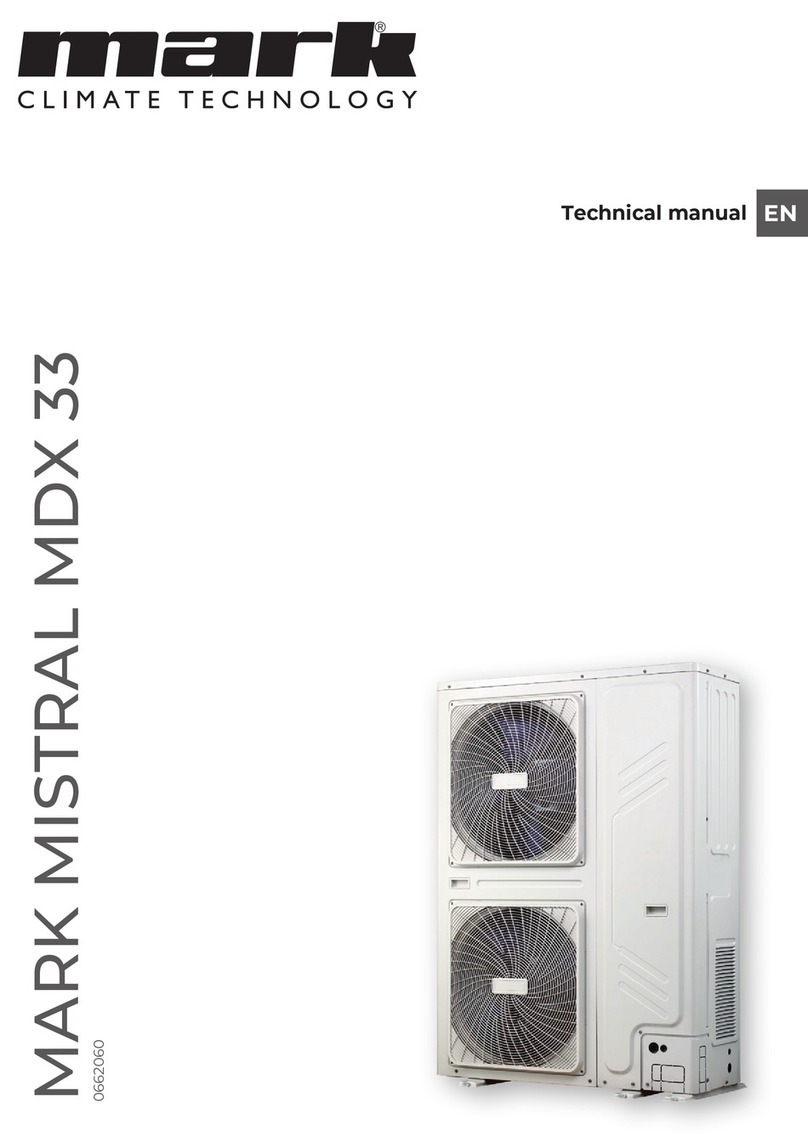
Mark MISTRAL MDX 33 User manual

MARK MISTRAL MDX 33/56
0662080
Technical manual EN

2

EN
3
READ THIS DOCUMENT BEFORE
INSTALLING THE HEATER
Warning
Incorrect installation, adjustment, alteration, repair or maintenance work may
lead to material damage or injury. All work must be carried out by certified,
qualified professionals. If the appliance is not positioned in accordance with the
instructions, the warranty shall be rendered void. This appliance is not intended
for use by children or persons with a physical, sensory or mental handicap, or
who lack the required experience or expertise, unless they are supervised or have
been instructed in the use of the appliance by somebody who is responsible for
their safety. Children must be supervised to ensure that they do not play with the
appliance.
1 General
1.1 Application
Appliance type MISTRAL MDX is solely suitable for the free and direct intake of the air to
be heated and the free discharge of heated air into the room. If areas are to be heated
in which corrosive vapours are present (chlorinated hydrocarbons in particular), which
are either produced directly in the area, or which may be drawn in from the outside by
the heater via a duct or an open connection, wall air heaters cannot be used because
of the risk of corrosion to the heat exchanger.
Subject to change
The manufacturer is committed to constantly improving its products and reserves
the right to make changes in the specifications without prior notice. The technical
details are considered correct but do not form the basis for a contract or warranty. All
orders are accepted according to the standard terms of our general sales and delivery
conditions (available upon request). The information in this document is subject to
change without notice. The most recent version of this manual is always available at
www.markclimate.com/downloads.
1.2 General warnings
Incorrect installation, adjustment, alteration, maintenance or repair of the MISTRAL
MDX may lead to material or environmental damage and/or injuries. The appliance
should therefore be installed, adapted or converted by a qualified and certified
installer, taking into account national and international regulations. Faulty installation,
adjustment, alteration, maintenance activity or repair shall render the warranty void.

4
2 Technical specifications
2.1 Technical specifications
Type MDX 33 MDX 56
Specifications indoor unit
Weight kg 94 157
Air flow max m3/h 6600 11200
Sound pressure level (5 mtr.) at max air flow dB(A) 53 56
Throw m 19 22
Pipe diameter Liquid Ø mm (inch) 12,7 (1/2”) 15,8 (5/8”)
Gas Ø mm 28 28
Power supply Ph/V/(Hz)kW 1/230/(50)0,24 1/230/(50)0,48
Temperature range Cooling °C +17 ~ +43 +17 ~ +43
Heating °C +7 ~ +25 +7 ~ +25
Condensate1kg/h 12 19
1 Indoor air temperature 27°C and 50% humidity
2.2 Dimensions
MDX 33 MDX 56
A
940
A
879
70 147
662
I
560
H
26 G26
G2626
M10
D C
F
E
180
154
61
102
B
47
n
40
J
Type A B C D E F G H I J K
MDX 33 1170 399 178 156 28 1/2” 1118 105 68 404 47
MDX 56 1800 373 206 154 28 5/8” 1748 140 33 389 47

EN
5
2.3 Assembly suggestions
3 Unit Placement and Installation
3.1 Positioning the appliance
After unpacking, check the appliance for damage. Check that the information relating
to the type/model and the electrical voltage is correct. Place the appliance and any
accessories to a sufficiently solid structure, taking into account the minimum free
space required.
3.2 Indoor units
3.2.1 Placement considerations
Placement of indoor units should take account of the following considerations:
»Indoor units should not be exposed to direct radiation from a high-temperature
heat source.
»Indoor units should not be installed in positions where dust or dirt may affect heat
exchangers.
»Indoor units should not be installed in locations where exposure to oil or to corrosive
or harmful gases, such as acidic or alkaline gases, may occur.
»Indoor units should be installed in well-drained, well-ventilated positions that are
as close as possible to the outdoor units.
»If applicable, sufficient space for drain piping and for access during servicing and
maintenance should be allowed.
»To ensure a good cooling/heating effect, short-circuit ventilation (where outlet air
returns quickly to a unit’s air inlet) should be avoided.
»To prevent excessive noise or vibration during operation, suspension rods or other
weight-bearing fixings should typically be able to bear twice the unit’s weight.
»Before installing an indoor unit, check that the model to be installed is as specified
in the construction drawings and confirm the correct orientation of the unit.
»Ensure that units are installed at the correct height.
»To allow smooth condensate drainage and to ensure unit stability (to prevent
excessive noise or vibration), ensure that units are level to within 1° of the horizontal.
If a unit is not level to within 1° of the horizontal, water leakage or abnormal vibration/
noise may occur.

6
3.2.2 Spacing
For indoor units to function properly, a sufficient air flow through the heat exchanger
must take place. The spacing of the indoor units must take into account that sufficient
air may flow through each unit. Figures 3.1 to 3.3 show spacing requirements in three
different scenarios.
Figure 3.1 Top view
A
A
45°
min
90°
max
A
min50
mm
min 1800mm
min 1000 mm
min 600 mm
min 1000 mm
TOPVIEW SIDEVIEW
Figure 3.2 Side view
A
A
45°
min
90°
max
A
min50mm
min 1800mm
min 1000 mm
min 600 mm
min 1000 mm
TOPVIEW SIDEVIEW
Figure 3.3 Front view
3.2.4 Acceptance and unpacking
»When units are delivered, check whether any damage occurred during shipment.
If there is damage to the surface or outside of a unit, submit a written report to the
shipping company.
»Check that the model, specifications and quantity of the units delivered are as
ordered.
»Check that all accessories ordered have been included. Retain the technical manual
for future reference.
3.2.5 Hoisting
»Do not remove any packaging before hoisting. If units are not packaged or if the
packaging is damaged, use suitable boards or packing material to protect the units.
»Hoist one unit at a time, using two ropes to ensure stability.

EN
7
3.3 Condensate drain (optional)
If the Mistral MDX is used for heating only, a condensate drain is not necessary.
Type MDX 33 MDX 56
Condensate1kg/h 12 19
1 Indoor air temperature 27°C and 50% humidity
3.3.1 Condensate drain with natural progression
The condensate drain must meet the criteria as described in the manual of the outdoor
unit.
Figure 3.3 Condensate drain without pump
B
n40
A
Type A B
MDX 33 404 47
MDX 56 389 47
3.3.2 Condensate drain with condensate pump
If there is a condensate drain pump in the Mistral MDX. Then the pipe to drain the
condensed water must be connected to the Mistral MDX. The drain must meet the
criteria as described in the manual of the outdoor unit.
Figure 3.4 Condensate drain with pump
A
B
Type A B
MDX 33 102 61
MDX 56 102 61

8
Figure 3.5
Discharge head (m)
Flow rate (l/h)
3.4 Outdoor units
For placement of the outdoor unit, please see the technical manual of the specific
outdoor unit.
4 Maintenance
4.1 Cleaning
For optimal performance, the Mistral MDX has to be cleaned on a regular basis.
4.2 Cleaning air diverter plate
An air diverter plate is present in the Mistral MDX. This serves to divert the blown air
over the battery. As a result, no high speed differences arise.
The air diverter plate becomes dirty over time, which affects the functioning. The plate
should be cleaned annually or more often if necessary. The Mistral MDX 33 has one
diverter plate, the Mistral MDX 56 has two diverter plates. These two diverter plates are
connected to each other shown in Figure 4.1. Take this into account while removing
and placing back the diverter plates.

EN
9
Figure 4.1 Cleaning air diverter plate
4.3 Replacing a broken condensate pump
When the condensate drain pump breaks down, it must be replaced. The location of
the pump is shown in the figure.
Figure 4.4 Replacing a broken condensate pump

10
4.3 Positioning sensors
T1 = Incoming air temperature
T2A = Average battery temperature
T2 = Incoming refrigerant temperature
T2B = Outgoing air temperature
TA = Outgoing refrigerant temperature
There are five sensors in the Mistral MDX. These are mounted in the places as shown
in the Figures 4.5-4.8. If one or more sensors fail, they must be replaced. Sensor T1 can
be replaced via the control box. To replace the other four sensors, it is first necessary
to disassemble the outlet louvre.
Figure 4.5 Position sensors
Temperature sensorExtension wire
T2B
WhiteWhiteWhite
Black BlackBlack
Red Red
White
T2A
Blue
BlackBlack
BlueBlue
Red
T1, TA
T2A, T2,
T2B
Figure 4.6 Position sensors
T2
T1
T2A
TA
T2B

EN
11
Figure 4.7 Position sensors
T1 TA
T2
T2B
When mounting the sensors, it is important that moisture cannot enter the sensors.
Figure 4.8 Position sensors

12
5 Refrigerant Piping
For information about the refrigerant piping, please see the technical manual of the
specific Mistral MDX outdoor unit.
6 Control board settings
6.1 0-10V Output control
The DIP switch numbers of ENC2, ENC3 and ENC4 correspond to different voltage
outputs. Depending on the DIP switch numbers of SW1-2, there are two control modes
available, which are gear 1 and gear 3 fan speeds, respectively.
1. SW1-2 dialled to “OFF” (factory default)
ENC2, ENC3 and ENC4 are respectively defined as low, middle and high voltage output
signals. By default, ENC2 is set to 2V, ENC3 is set to 7V, and ENC4 is set to A (A is 10V).
See the table below for their corresponding relations:
Figure 6.1 0-10V output Voltage
ENC2
(2V Factory Default)
ENC3
(7V Factory Default)
ENC4
(10V Factory Default)
Fan output voltage of Low speed Fan output voltage of Middle speedFan output voltage of High speed
Voltage(V)
Dial code 0
1
1
1
2
2
3
3
4
4
5
5
6
6
7
7
8
8
9
9
A
10
B
10
C
10
D
10
E
10
F
10
Note: ENC2<ENC3<ENC4. If not satisfied, fault H9 is reported.
6.2 Capacity settings
The capacity DIP switches for the AHU control box should be set after the box is
installed. The capacity can be set through ENC1 and SW4-2. After completing the
settings, power off and then power on the unit to apply the settings.
NOTE: Each AHU control box in parallel connection should undergo capacity settings.
Figure 6.2 Capacities of SW4-2 and ENC1
Capacity
(hp)
Capacity
(KW)
1
4
12.0 hp
20.0 hp
33.5
56.0
ON
1234
SW4-2 ENC1
1MDX 33
MDX 56

EN
13
6.3 Setting the Master/Slave AHU Control Box
1. If multiple AHU control boxes are connected in parallel, the master/slave AHU control
box needs to be set through SW2-3 and SW2-4
Figure 6.3
ON
1234
SW2-3 and SW2-4 are 00:
master AHU control box
(factory default)
SW2
6.4 Selection of Controllers
The Mistral MDX is controlled by a Pintherm Mistral. To apply the Pintherm Mistral,
SW4-3 and SW4-4 must be set as follows:
Figure 6.3 SW4-3, SW4-4
SW4-3 and SW4-4 are 01:
capacity output mode of a third
party controller
ON
1234
NOTE: After DIP switches on main board are set, remember to power off and then
power on the main board to apply the settings. Otherwise, the settings will be invalid.
When a third party controller is used, two control modes are available: capacity output
control mode and set temperature control mode.
7 Electrical Wiring
7.1 General
CAUTION!
»All installation and wiring must be carried out by competent and suitably qualified,
certified and accredited professionals and in accordance with all applicable
legislation.
»Electrical systems should be grounded in accordance with all applicable legislation.
»Overcurrent circuit breakers and residual-current circuit breakers (ground fault
circuit interrupters) should be used in accordance with all applicable legislation.
»Wiring patterns shown in this data book are general connection guides only and
are not intended for, or to include all details for, any specific installation.
»The refrigerant piping, power wiring and communication wiring are typically run in
parallel. However, the communication wiring should not be bound together with
the refrigerant piping or power wiring. To prevent signal interference, the power
wiring and communication wiring should not be run in the same conduit. If the
power supply is less than 10A, a separation of at least 300mm between power wiring
and communication wiring conduits should be maintained; if the power supply is
in the range 10A to 50A then a separation of at least 500mm should be maintained.

14
7.2 Power Supply Wiring
Power supply wiring design and installation should adhere to the following
requirements:
»Separate power supplies should be provided for the indoor unit and outdoor unit.
»Installation must comply with the relevant local and/or national regulations.
7.3 Communication Wiring
Communication wiring design and installation should adhere to the following
requirements:
»0.8mm2 three-core shielded data cable should be used for communication wiring.
Using other types of cable can lead to interference and malfunction.
»Indoor communication wiring:
- The P and Q communication wires should NOT be grounded.
- The shielding nets of the communication wires should be connected together
and grounded. Grounding can be achieved by connecting to the metal casing
adjacent to the P Q E terminals of the outdoor unit electrical control box.
»The on/off contact (connectors 10 and 11) can be used for:
- Smart grid
- Fire alarm
- External on/off
The communication wires should be connected to the outdoor unit terminals indicated
in the following paragraph.

EN
15
7.4 Wiring example

16
7.5 Electrical diagram

EN
17

18

EN
19

MARK BV
BENEDEN VERLAAT 87-89
VEENDAM (NEDERLAND)
POSTBUS 13, 9640 AA VEENDAM
TELEFOON +31(0)598 656600
FAX +31 (0)598 624584
www.mark.nl
MARK EIRE BV
COOLEA, MACROOM
CO. CORK
P12 W660 (IRELAND)
PHONE +353 (0)26 45334
FAX +353 (0)26 45383
www.markeire.com
MARK BELGIUM b.v.b.a.
ENERGIELAAN 12
2950 KAPELLEN
(BELGIË/BELGIQUE)
TELEFOON +32 (0)3 6669254
www.markbelgium.be
MARK DEUTSCHLAND GmbH
MAX-PLANCK-STRASSE 16
46446 EMMERICH AMRHEIN
(DEUTSCHLAND)
TELEFON +49 (0)2822 97728-0
TELEFAX +49 (0)2822 97728-10
www.mark.de
MARK POLSKA Sp. z o.o
UL. JASNOGÓRSKA 27
42202 CZĘSTOCHOWA POLSKA
PHONE +48 34 3683443
FAX +48 34 3683553
www.markpolska.pl
MARK SRL ROMANIA
STR. BANEASA NO 8 VIA STR. LIBERTATII
540199 TÂRGUMURES, JUD MURES
(ROMANIA)
TELFAX +40 (0)265-266.332
www.markromania.ro
CERTIFICATION N°: 17.07.011
AIRSTREAM
Other manuals for MISTRAL MDX 33
1
This manual suits for next models
1
Table of contents
Other Mark Heat Pump manuals