Marport PRO SPEED User manual


Contents
Legal 4
History 4
Copyright 4
Disclaimer 4
Introduction and
Presentation 5
Introduction 6
Applications 7
Safety Guidelines 8
Description 8
System Compatibility 8
Firmware and Features 9
Technical Specifications 10
Main Parts 12
Sensor Configuration 14
Connecting the Sensor to Mosa2 15
Battery Information 18
Diagnostic Information 19
Uploading the Sensor Firmware 20
Configuring the Trawl Node 23
Configuring the Uplink Frequency and
Power 24
Configuring the Echo Sounder 25
About the Automatic Range Mode 27
Calibrating the Sensor for Target Strength
Value 29
Calibrating the Speed 34
Checking Speed Measures with EM Log
Tester 36
Applying Osets to Measurements 38
Testing Measures 40
SD Card Recording 41
Saving a Configuration on Mosa2 43
Exporting Sensor Configuration 46
Importing a Sensor Configuration 46
System Configuration and
Display 48
Adding the Sensors to the Receiver 49
Configuring the Sensor Settings 50
Configuring Data Display in Scala2 51
Outputting Scala2 Symmetry Data to Scantrol
55
Replaying Data from A2S Files 58
Installation 60

Contents | iii
Installing the Sensor on the Trawl 61
Maintenance and
Troubleshooting 64
Identifying and Deactivating Sensor Alarms
65
Checking Noise Interference 65
Charging the Sensor with the Dock 69
Cleaning the Sensor 70
Maintenance Checklist 71
Troubleshooting 72
Mosa2 does not open due to error message 72
Sensor does not connect correctly with Mosa2
when using the Configuration Cable 73
The echogram has a lot of interference 74
Speed data is wrong 76
Support Contact 77
Appendix 78
Frequency Plan 78
Examples of Installations for a Target
Strength Calibration 83
Examples of Installations for a Speed
Calibration 87
Index a

Legal
History
V1 12/30/22 First release
Copyright
© 2022 Marport. All Rights reserved.
No part of this document may be reproduced, stored in a retrieval system or transmitted in any
form by any means; electronic, mechanical, photocopying or otherwise, without the express
written permission from Marport. “Marport”, the Marport logo and Soware Defined Sonar are
registered trademarks of Marport. All other brands, products and company names mentioned
are the trademark and property of its respective owners only. Marport is a division of Airmar
Technology Corporation.
Disclaimer
Marport endeavors to ensure that all information in this document is correct and fairly stated, but
does not accept liability for any errors or omissions.
Speed Navigator | V1 | Legal 4


Introduction and Presentation
Get a basic knowledge of the sensor.
Introduction
Marport's Speed Navigator is a high-definition net sounder, designed to operate on the
trawl headline and tunnel.
It measures the speed of the water flow in two axis: the flow along the direction of the
trawl and across it. This way, you can monitor if the trawl is moving at the right speed
and with the right geometry. It measures along speed up to 6 knots and cross currents
speed up to 3 knots. It also track pitch, roll, depth and temperature data.
The high-definition echogram images allows you to see fish passing through the trawl
and have an overview of the trawl opening.
In order to eiciently follow the trawl descent, echogram ranges are configurable from
5 to 160 meters. Moreover, the sensor includes an automatic range mode: the sensor
can automatically switch to lower ranges of 20, 10 and 5 meters to get sharper pictures,
proving to be particularly useful when fishing close to the bottom.
Optionally, the sensor can also measure the temperature, depth, pitch and roll.
Speed Navigator | V1 |
Introduction and Presentation 6

Applications
Examples of data received and displayed in Scala2 application.
Below is an example of data received from the sensor. The autorange mode is activated,
so the sounding range changes to 20, then 10 meters as the sea bottom gets closer. See
About the Automatic Range Mode (on page 27) for more details about this mode.
1. Maximum range (80 m) / 2. Switch to a 20-meter range / 3. Switch to a 10-meter range
Speed Navigator | V1 |
Introduction and Presentation 7

Example of higher quality echogram images when the range reduces automatically,
here to 10 meters.
Safety Guidelines
Important: To ensure proper and safe use of this equipment, carefully read
and follow the instructions in this manual.
Description
System Compatibility
The Speed Navigator is compatible with the following versions of Marport's soware
and equipment.
Mosa2 02.11.10 or later
Scala2 02.10.03 or later
Mx receiver firmware 08.05.03 or later
Dock 01.01.01 or later
Speed Navigator | V1 |
Introduction and Presentation 8

Firmware and Features
This section describes the firmware and features that must be configured on MASP to
set up the sensor.
To be operational, the sensor needs to be configured with two files:
•a firmware file (*.A2F): it is the firmware of the sensor,
•an application file (*.A2A): it defines the sensor features and options.
These files are generated via MASP.
See Uploading the Sensor Firmware (on page 20) for guidance on how to complete
the following items and download the firmware and application files.
Firmware
The latest version of the firmware is available for download on MASP.
Compatibility: F450-02.02.02 and aer
Features and Options
The features and options are configurable according to the type of hardware and
customer's choices.
Features •Product name: Manually entered.
•Application: Speed Navigator or Speed
Navigator Reversed
•Body: Tets
•Battery capacity (not configurable): 2-
pack
Sounding Options (non-editable) •Up
•Down
Misc. options •SD Card Log: records a log of the sen
sor activity. This option is useful for trou
bleshooting support.
Speed Navigator | V1 |
Introduction and Presentation 9

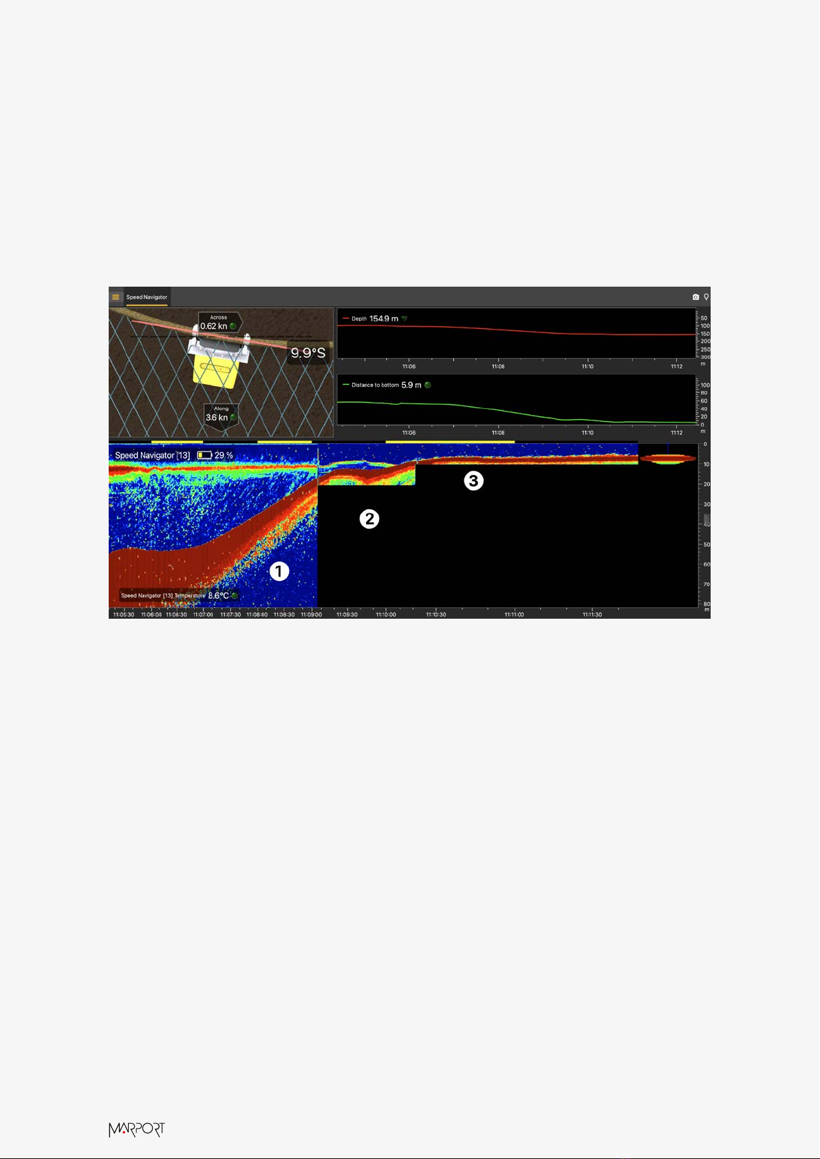
Measures •Battery (always activated)
•Across Speed (always activated)
•Along Speed (always activated)
•Pressure (depth)
•Temperature
•Pitch
•Roll
Technical Specifications
Uplink frequency 30 to 60 kHz
Range to vessel up to 2500 m*
Data update rate •5-meter range: Echogram @0.16 s - temperature, depth, pitch, roll,
battery level, along speed, across speed @8.07 s
•10-meter range: Echogram @0.31 s - temperature, depth, pitch,
roll, battery level, along speed, across speed @8.82 s
•20-meter range: Echogram @0.63 s - temperature, depth, pitch,
roll, battery level, along speed, across speed @8.79 s
•40-meter range: Echogram @0.84 s - temperature, depth, pitch,
roll, battery level, along speed, across speed @5.84 s
•80-meter range: Echogram @0.89 s - temperature, depth, pitch,
roll, battery level, along speed, across speed @6.22 s
•160-meter range: Echogram @0.99 s - temperature, depth, pitch,
roll, battery level, along speed, across speed @6.99 s
Depth range up to 1800 m
Depth resolution 0.1 m with 0.1% full scale accuracy
Echogram range 5 (auto) / 10 (auto) / 20 (auto) / 40 / 80 / 160 meters
Pitch and roll range -180° to +180°
Pitch & roll accuracy +/- 1°
Temp measurement range -5° C to +25° C
Temp accuracy ±0.1° C
Across speed range Up to ± 3 knots
Speed Navigator | V1 |
Introduction and Presentation 10

Along speed range Up to ± 6 knots
Battery type Lithium-Ion
Weight of sensor + protec
tion cage in air
22.4 kg
Weight of sensor + protec
tion cage in water
13 kg
Warranty 2 years (Sensor & Battery) **
*Reference only. Depends on communication settings and transmission conditions /
† Depends on sensor uplink power and options. Lifetime has been estimated with a
uplink power at 33%. / ‡ Based on average charging time. / **Marport Standard Marine
Limited Warranty
Dimensions
Speed Navigator | V1 |
Introduction and Presentation 11

Setup with a board for a reversed installation:
Main Parts
External View
1. Temperature sensor
2. Negative charge
3. Water switch
4. Positive charge
5. Shoulder bolts
6. Pressure-relief spring
7. Pressure sensor
8. EM log pins
9. Latch
Exploded View
1. Transducer
2. Sarah Connor PCBA
3. Battery
4. End cap
5. Sensors
6. EM log
7. PCBA
Speed Navigator | V1 |
Introduction and Presentation 12

PCBA Connectors
The Speed Navigator has two PCBAs:
•PCBA version A2S Gen 4 (P/N 25-1023-04) and aer:
1. Batteries
2. Connection to Sarah Connor
PCBA
3. Water-switch
4. Down (A)
5. Up (B)
6. Uplink (C)
7. Temperature and pressure
(T&D)
•Sarah Connor PCBA:
1. Connection to
A2S PCBA
2. Electromagnetic
coil
3. EM log pins
Speed Navigator | V1 |
Introduction and Presentation 13


Sensor Configuration
Learn how to configure the sensor settings.
To be able to change the settings of the sensor: Press command + A or click Menu
and click User Mode > Advanced.
Connecting the Sensor to Mosa2
To configure the sensor, you need to connect it to Mosa2 application, using either the
Dock or the Configuration Cable.
Using a Dock Charger Plug
Speed Navigator | V1 | Sensor Configuration 15

1. Connect one Dock charging plug to the sensor's endcap.
2. Mosa2 discovery page opens. The sensor is displayed.
◦Click to open the sensor
configuration page.
◦Click to show the deploy
animation on the charger plug
for 30 seconds.
Using the Configuration Cable
Simply connect the Configuration Cable from the computer to the sensor to display the
sensor configuration page on Mosa2.
Tip: Refer to the Configuration Cable Quick Reference Guide for more details
about the use of this product.
1. Move other electrical devices minimum 1 m away from the computer.
2. Connect the USB connector directly to the computer.
Speed Navigator | V1 | Sensor Configuration 16

Mosa2 opens automatically and the startup wizard is displayed. The LED on the
plug is solid blue.
3. Connect the three-pin plug to the sensor.
The LED on the plug blinks alternatively blue and green.
4. Wait a few seconds. The configuration page of the sensor is displayed on Mosa2.
The LED on the plug is solid green.
You can now configure the sensor.
Note: You can keep the Configuration Cable continuously connected by
USB, and virtually eject or connect it. When no sensor is connected to
the Configuration Cable, click Menu > Eject Config Plug or Connect
Config Plug. When ejected, you come back to the discovery page. It stays
disconnected until you virtually connect to it or manually disconnect then
connect it.
Speed Navigator | V1 | Sensor Configuration 17

Battery Information
The battery lifetime is displayed on the first page.
Speed Navigator | V1 | Sensor Configuration 18

You can also check the battery level at anytime from the top bar:
Note: When you change settings such as the uplink power or sounding
range, it aects the battery consumption and remaining lifetime. The battery
information will update aer the sensor has been switched on and operating
for 10 minutes.
Diagnostic Information
Scala2 and Mosa2 applications warn the user in case of water ingress in the sensor.
Note: Diagnostic information is available for Marport Pro sensors (A2S and A2H
PCBA versions), from the firmware version F450-02.02.00 or later and Mosa2
version 02.11.08.
Speed Navigator | V1 | Sensor Configuration 19

In case of water ingress in the sensor, alarms are displayed in Scala2 Virtual Charger
Room, in Mosa2 and on the charger plug when connected to the sensor.
•Mosa2 displays a dialog at the start of the application and warning icon in the
toolbar and diagnostic page:
•The charger plug displays a warning icon:
When the alarm appears, the sensor needs to be taken out of water immediately,
checked and repaired. Once repaired, complete the procedure explained in Identifying
and Deactivating Sensor Alarms (on page 65).
Warning: In case of water ingress in the product, do not charge it: battery may
vent or rupture, causing product or physical damage.
Uploading the Sensor Firmware
When preparing the sensor for the first time, you need to upload firmware and
application files into it.
You need to have the following files:
•a firmware file (*.A2F): it is the firmware of the sensor,
•an application file (*.A2A): it defines the sensor features and options.
Aerward, when new improved versions of firmware are released, you will only have to
upload the firmware file. If you need to change the options of the sensor (e.g. pitch &
roll, temperature), only upload the application file.
Speed Navigator | V1 | Sensor Configuration 20
Table of contents
Other Marport GPS manuals