Marquis 3000 SM User manual

OWNERS’ MANUAL
3000 SM
4000 SM
4500 SM
5500 SM
6500 SM
CIRCLE THE MODEL OF YOUR
COOLER AND RECORD THE SERIAL
NUMBER BELOW.
READ CAREFULLY ALL OF THIS
MANUAL BEFORE INSTALLING THE
UNIT
ENCIERRE CON UN CIRCULO EL
MODELO DE SU ENFRIADOR Y ESCRIBE
EL NUMERO DE SERIE ABAJO.
LEA CON CUIDADO TODO ESTE MANUAL
ANTES DE INSTALAR LA UNIDAD
SERIAL #
NUMERO DE SERIE
SAFETY RULES
1. Read instructions carefully.
2. Electrical hook up should be done by a qualified electrician,
so that all electrical wiring will conform to your local
standards.
3. Always turn OFF POWER and UNPLUG motor and pump
inside the cooler before installing or performing any
maintenance.
4. Your cooler will run on 120 volt A.C., 60 Hz (cycle) current
only.
5. Motor and pump have a grounded, molded plug and an
automatic thermal overload switch which will shut motor off
whenitoverheats. Themotorwillrestartautomaticallywhen
it cools down.
WARNING:To reduce the risk of fire or electric shock,
do not use this fan with any “solid-state fan speed control
device.”
READ AND SAVE THESE INTRUCTIONS EVAPORATIVE COOLING
With this unit being a fresh air system, you are not trapped
with recirculating air that can become stale, laden with smoke
and odors, as happens with refrigerated air conditioning
systems. Instead, you are completely replacing the air every
2 to 4 minutes by either opening doors or windows or a
combination of both to exhaust the air continually.
VEA EL ESPAÑOL EN EL INTERIOR.
110520 4-01
OPERATION
To eliminate delivery of hot air when starting cooler, turn on
pump only for the first few minutes, then turn on the blower
motor.
These coolers may be used without water for ventilation
purposes. When outside air is cool (for example, at night) or
when humidity is high the water pump can be turned off.
A cooler can also be installed with a thermostat and attic
exhaust dampers to provide completely automatic operation.
www.championcooler.com

2110520
INSTALLATION
NOTE: The pump and float are installed in the cabinet. The
belt, motor pulley, and motor cord are included in the cabinet,
the motor is shipped separately.
CAUTION: Make sure that the mounting surface is
strong enough to support the operating weight of the
cooler when in use. (For operating weight, see
Specification Table.)
CAUTION: Never plug in cooler until installation is
complete and unit has been tested for rigidity.
MOTOR INSTALLATION
•Install motor cord. Connect motor cord to motor using the
following color code: Black - Hi, Red - Low, White - Com.,
Green - Ground.
BLOWER
HOUSING
MOTOR
PULLEY
BLOWER
PULLEY
FIG. 2
•Mount motor. Installblower motor in the motor mount yokes,
adjusting the yoke if necessary. Fasten with the provided
mounting clips (see Fig. 1).
•Install pulley. Install the adjustable motor pulley so that it
aligns with the blower drive pulley (see Fig. 2) and tighten
set screw.
ELECTRICAL INSTALLATION
WARNING: Disconnect all electrical service that will
be used for this unit before you begin the installation.
•Remove junction box.
The electrical junction
box is located in the up-
per inside corner of the
coolercabinet. Remove
thetwoscrews and slide
cover down for access
to plug wiring (Fig. 3).
•Hook up electrical. Electrical hook up should be done by a
qualified electrician, so that all electrical wiring will conform
to your local standards. See Fig. 4 for the wiring diagram.
IMPORTANT: When a single speed motor is used, do not
use the red lead on the receptacle and motor plug wiring.
Tape off end of both of the red leads.
WARNING: Make sure that cooler cabinet is properly
grounded to a suitable ground connection for maximum
safety.
SCREWS
FIG.3
JUNCTION
BOX
OPEN WINDOWS TO EXHAUST AIR
An often misunderstood concept of evaporative cooling is the
amount of air that should be exhausted. How much should
you open your windows? The fact is that most people do not
open their windows enough. The following two methods will
help you determine the amount to open your windows.
FIRST METHOD
You should allow an opening of at least 2 square feet (288
square inches) for each 1000 CFM rating of your unit.
Example: At 2973 CFM, model 4000 SM requires 6 square
feet (856 square inches) of opening (2973/1000 * 2 = 6).
Multiply the number of windows by window width in inches
and divide this into the number of square inches required for
your size unit. This will give you the height to open windows.
In this example, four 36 inch wide windows should be opened
6 inches each.
CHAMPION AIR BALANCING METHOD
1. Take a piece of tissue paper and cut it lengthwise into 3
equal strips.
2. Turn your cooler on high cool.
3. Open one window at least six inches wide in each room
that you want to cool.
4. Take the piece of tissue paper and put it up against the
screen of the open window furthest from the cooler dis-
charge opening. Let go of it. It will do one of three things.
IF It falls down.
THEN CLOSE all of the windows one inch and try step 4
again.
IF It plasters itself to the screen.
THEN OPEN all of the windows one inch and try step 4
again.
IF It stays on the screen lightly.
THEN PERFECT. You are done. Enjoy your cooler.
NOTES:
• When switching to low cool, you must rebalance your home.
Repeat step 4.
• Onceyou balance your home you cancool some areas more
than others by opening those windows more and closing the
others by the same amount. Repeat step 4 to make sure
your home is still air balanced.
MOTOR
CLIPS
ADJUSTABLE
YOKE
FIG. 1
WATER CONNECTION
•Install overflow assembly. Remove nut and place nipple
through the hole in the pan, with the rubber washer between
the pan and the head of the drain nipple (Fig. 5). Screw on
nut and draw up tight against bot-
tom of pan. Insert overflow pipe in
nipple to retain water. Overflow
pipe may be removed to drain pan
when necessary. A garden hose
may be screwed on the drain
nipple to drain water away from
your unit.
RUBBERWASHER
OVERFLOW PIPE
NIPPLE
BOTTOM PAN
NUT
FIG. 5
BLACK
RED
GREEN
WHITE
BLACK/BLUE
HI
LO
COM.
PUMP
GROUND
TO SWITCH
WHITE
GREEN
GROUND 115 VOLTS
60 HERTZ
FIG. 4

3
110520
•Connect water supply line.
Find the closest supply of wa-
ter. Use a saddle valve (Fig. 6)
to connect 1/4” tubing to the
cold water supply or use a
Sillcock and water valve con-
nected to an outside faucet
(Fig. 7). Place the nut and fer-
rule on the tubing and tighten
the nut until water tight. IM-
PORTANT: Donotconnectthe
water supply to any soft water
applications. Soft water will
cause corrosion and de-
crease the life of the cooler.
•Attach water line to float.
Attach the water supply line
to the float in the same man-
ner as above. The float may
be installed in either the cor-
ner post or bracket (Fig. 8).
•Fill pan. Allow water to fill to
within1”oftopofpanandad-
just float to maintain this
water level. This can be ac-
complished by bending the
float rod.
•Adjust water amount. Your
cooler is equipped with a unique
water metering valve (Fig. 9). The amount of water deliv-
ered to the pads may be decreased by pressing the plastic
valve as the arrows indicate. If wa-
ter is splashing out of water troughs,
you may need to decrease the
amount of water delivery. Check to
see that all pads are saturated with
water and that there are no dry spots
or openings in the pads.
INCREASE
DECREASE
FIG.9
FAUCET
WATER SUPPLY
VALVE
SILLCOCK
FERRULE
NUT
FIG. 7
COLD
WATER
PIPE
SADDLE
VALVE
1/4” TUBING
FIG. 6
DEPRESSHERE
TO REMOVE
FIG. 12
be done for your safety. Adjust pulley
to a larger diameter and readjust belt
tension, plug motor in, install pad
frame, and retest amperage draw.
Repeat this process until correct
amperagedraw is attained. Increas-
ing motor pulley diameter increases
amperage draw. Decreasing motor
pulley diameter decreases amperage
draw (see Fig. 10).
CAUTION: Do not operate cooler with larger amper-
age draw than specified on motor plate.
NOTE: No attempt should be made to completely install this
unit without the aid of an electrician or someone familiar with
testing amperage draw. Failure to comply with these instruc-
tions may void your warranty.
FIG. 11
3 LB.
3/4 INCHES
MAINTENANCE
WARNING:Before doing any maintenance be sure
power is off. At the time you remove a pad frame be sure
to unplug motor and pump. This is for your safety.
SPRING START-UP
•Oil bearings. The blower bearings and cooler motor in this
unit should be oiled with a few drops of non-detergent 20/30
weight oil once each year. The motor does not need oil if it
has no oil lines for oiling. Motors that have no oil lines are
lifetime oiled at the factory and require no further oiling for
the life of the unit.
CAUTION:Do not over oil. Over oiling can cause motor
burnout,due to excessive oil getting into
motor winding.
•Check belt tension. A 3 lb.
force should deflect the belt 3/
4 inches (see Fig. 11). Read-
just belt if needed.
•Change Pads. The pads should be replaced once or twice
a season, depending upon the length of the season. At the
beginning and at mid season a clean pad is more absorbent
and efficient and will deliver substantially more cool air.
•Clean pump. Clean-
ing the pump is
necessary once a year
at start-up. For your
safety, turn unit off and
unplug motor and
pump. Remove the
pump from the mount
slot. Remove the base
of the pump as shown
in Fig. 12. Clean the
pump and turn the impeller to ensure free operation. Re-
move the pump spout and check for any blockage. After
cleaning, reinstall the base onto the pump. Reattach the
pump to the mount in the cooler using the plastic retainer to
ensure that the pump will not overturn. Do not forget to re-
placethespout and water delivery tube ontothepump outlet.
The pump has automatic reset thermal protection.
AMPERAGE DRAW AND BELT TENSION
This unit is equipped with an adjustable motor drive sheave
for adjusting the blower wheel speed to the proper loading on
different duct systems. It is important that the motor drive pul-
ley is adjusted to correct size to assure maximum air delivery
without damage to the motor. Be sure to follow these instruc-
tions carefully.
•Adjust drive pulley. After the unit is completely installed,
adjust the drive pulley to the least diameter and adjust belt
tension. See the maintenance section for adjusting belt ten-
sion.
•Start cooler. Install all pad frames, start pump, and allow to
operate until pads are wet.
•Check amperage. With pads wet and unit started, check
amperage draw with an amperage meter.
•Adjust pulley if necessary. If amperage draw is less than
motor rating, turn off electrical power and remove pad frame.
Unplug motor inside cooler, this will protect you from some-
oneturning on unit whileyou are working inside. Thisshould
DECREASE
AMPERAGE
FIG. 10
FLOAT
CORNER
POST BRACKET
FIG. 8

4110520
WINTER SHUT DOWN
•Drain water. Always drain all of the water out of the cooler
and water supply line when not in use for prolonged periods,
and particularly at the end of the season. Keep the water
line disconnected from boththe unit and water supply so that
it does not freeze.
•Unplug motor and pump. When cooler is not used for
extended periods, unplug the motor and pump from inside
cooler.
•Cover unit. To protect the life of the finish, a cover for the
unit is suggested in extended periods of non use.
By following the operating, installation, and maintenance
suggestions as outlined, you can get many years of efficient
and satisfactory service from your cooler. In the event addi-
tional information is desired,your dealer will be more than glad
to assist you in every possible way.
PROBLEM POSSIBLE CAUSE REMEDY
Failure to start or no
air delivery
Inadequate air
delivery with cooler
running
Inadequate cooling
Motor cycles on and
off
Noisy
Excessive humidity in
house
Musty or unpleasant
odor
Water draining onto
roof
1. No electrical power to unit
• Fuse blown
• Circuit breaker tripped
• Electric cord unplugged or damaged
2. Belt too loose or tight
3. Motor overheated
• Belt too tight
• Blower bearings dry
• Motor pulley diameter too large
4. Motor locked
1. Insufficient air exhaust
2. Belt too loose
3. Pads plugged
4. Motor underloaded
1. Inadequate exhaust in house
2. Pads not wet
• Pads plugged
• Open spots in pads
• Trough holes clogged
• Pump not working properly
1. Low voltage
2. Excessive belt tension
3. Blower shaft tight or locked
4. Bearings dry
5. Motor pulley diameter too large causing
motor overload
1. Bearings dry
2. Wheel rubbing blower housing
3. Loose parts
1. Inadequate exhaust
1. Stale or stagnate water in cooler
2. Pads mildewed or clogged
3. Pads not wetting properly
• Trough holes clogged
• Pump not working properly
1. Float arm not adjusted properly
2. Overflow assembly leaking
1. Check power
• Replace fuse
• Reset breaker
• Plug in cords or replace if damaged
2. Adjust belt tension
3. Determine cause of overheating
• Adjust belt tension
• Oil blower bearings
• Adjust pulley to correct diameter
4. Replace motor
1. Open windows or doors to increase air flow
2. Adjust belt tension or replace if needed
3. Replace pads
4. Adjust pulley to full load ampere rating of motor
1. Open windows or doors to increase air flow
2. Check water distribution system
• Replace pads
• Repack pads
• Clean trough and unplug holes
• Replace or clean pump (Unplug unit)
1. Check voltage
2. Adjust belt tension
3. Oil or replace bearings (Unplug unit)
4. Oil bearings
5. Adjust pulley so full load ampere rating of motor
is not exceeded
1. Oil bearings
2. Inspect and realign (Unplug unit)
3. Tighten loose parts
1. Open doors or windows
1. Drain pan and clean pads
2. Replace pads
3. Check water distribution system
• Clean
• Replace or clean pump (Unplug unit)
1. Adjust float
2. Tighten nut and overflow pipe.
TROUBLESHOOTING

5
110520
SNOITACIFICEPSROTOM /ROTOMLEDSENOICACIFICEPSE
.oNledoM oledoM #traProtoM °N-rotoM PHPH deepS dadicoleV stloV soitloV #traPyelluProtoM* °N-rotoMleDaeloP #traPdroClacirtcelE °N-ocirtcélEelbaC #traPtleBevirD °N-adnaB
MS0003 200-444011 200-544011 3/1 1
2511772011463011)054-L4(112011
MS0004 200-444011 200-544011 3/1 1
2511872011463011)075-L4(212011
MS0054 200-644011 200-744011 2/1 1
2511872011463011)075-L4(212011
MS0055 200-644011 200-744011 2/1 1
2511872011463011)076-L4(312011
MS0056 200-844011 200-944011 4/3 1
2511872011463011)076-L4(312011
/.D.OelbatsujdAxeroB"2/1* .elbatsujAonretxEortemáiDxsadaglup2/1edordalaT
SNOITACIFICEPSLARENEG /SELARENEGSENOICACIFICEPSE
.oNledoM oledoM
).sbl(thgieW )sarbil(oseP ).ni(snoisnemiDtenibaC )sadaglup(ajaCaLeDsenoisnemiD ).ni(gninepOtcuD )sadaglup(otcuDeDarutrebA
yrD oceS gnitarepO onelL thgieH arutlA htdiW aruhcnA htpeD dadidnuforP htdiW aruhcnA thgieH arutlA
MS000301130261/7338/1828/1828/5318/531
MS000454157261/31938/1438/1434/3714/371
MS005454167261/31938/1438/1434/3714/371
MS005559116361/72493934/3914/391
MS005659156361/72493934/3914/391
LIMITED WARRANTY
This warranty is extended to the original purchaser of an evaporative cooler installed and used under normal conditions. It
does not cover damages incurred through accident, neglect, or abuse by the owner. We do not authorize any person or
representative to assume for us any other or different liability in connection with this product.
TERMS AND CONDITIONS OF WARRANTY
For Eight Years from date of installation, we will replace the original base assembly if water leakage should occur due to rust
out.
For One Year from date of installation, we will replace any original component provided by Champion Cooler Corporation
which fails due to any defect in material or factory workmanship only.
EXCLUSIONS FROM THE WARRANTY
We are not responsible for replacement of cooler pads. These are disposable components and should be replaced periodi-
cally. We are not responsible for any incidental or consequential damage resulting from any malfunction.
We are not responsible for any damage received from the use of water softeners, chemicals, descale material, plastic wrap,
or if a motor of a higher horsepower than what is shown on the serial plate is used in the unit.
We are not responsible for the cost of service calls to diagnose cause of trouble, or labor charge to repair and/or the replace-
ment of parts.
HOW TO OBTAIN SERVICE UNDER THIS WARRANTY
Contact the Dealer where you purchased the evaporative cooler. If for any reason you are not satisfied with the response
from the dealer, contact the Customer Service Department: Champion Cooler Corporation, 5800 Murray Street, Little Rock,
THIS LIMITED WARRANTY APPLIES TO ORIGINAL PURCHASER ONLY

6110520
No. 4000SM 5500SM
N° Description / Descripción 3000SM 4500SM 6500SM
1. Top Pan / Tapa -------------------------------------------------------------------------------222903-002 220901-001 220903-001
2. Bottom Pan / Base De La Caja ------------------------------------------------------------222904-002 220902-001 220905-003
3. Louvered Side /Reja Lateral -------------------------------------------------------------- 324006-103 324007-103 324008-103
4. Aspen Pads / Filtros De Paja ------------------------------------------------------------- 110091 110090 110092
5. Pad Retainers / Soporte Para El Filtro -------------------------------------------------- 3PW-4 3PW-5 3PW-6
6. Corner Post, With Float Hole / Poste De Esquina, Con Agujero Para Flotador -224003-004 224003-005 224003-006
7. Corner Post, No Float Hole / Poste De Esquina, Sin Agujero Para Flotador-----224003-004 224003-005 224003-006
8. Front Panel / Panel De Frente -------------------------------------------------------------324106-001 324107-005 322108-004
9. Cut-Off Plate / Placa Externa -------------------------------------------------------------- 224002-001 224004-001 324108-005
10. Blower Housing / Caja De La Rueda -----------------------------------------------------324106-102 324107-006 324108-004
11. Blower Wheel / Rueda ---------------------------------------------------------------------- 12BW 16BW 20BW
12. Shaft, Blower Wheel / Eje De La Rueda-------------------------------------------------110182 110183 110183
14. Bearings, Blower Wheel Shaft / Cojinetes Del Eje De La Rueda -------------------110351 110351 110351
15. Pulley, Blower Wheel / Polea De La Rueda --------------------------------------------110274 110275 110276
16. Drive Belt / Banda De Transmisión-------------------------------------------------------- 110211 110212 110213
17. Motor / Motor --------------------------------------------------------------------------------- ***
18. Pulley, Motor / Polea Del Motor-----------------------------------------------------------110277 110278 110278
19. Motor Mount / Montura Del Motor --------------------------------------------------------314003-006 314003-004 314003-004
20. Motor Mount Clips / Seguros Para Montar Motor--------------------------------------314005-001 314005-001 314005-001
21. Electrical Cord, Motor / Cable Eléctrico Del Motor -----------------------------------110364 110364 110364
22. Float Valve / Válvula Del Flotador-------------------------------------------------------- FL-C FL-C FL-C
23. Pump Mount / Montura De La Bomba ---------------------------------------------------216003-001 216003-001 216003-001
24. Pump Screen / Malla Para La Bomba ---------------------------------------------------281001-001 281001-001 281001-001
25. Pump Assembly / Bomba ------------------------------------------------------------------NOR-120P NOR-120P NOR-120P
26. Pump Retainer / Sujetador De La Bomba ----------------------------------------------- 110866B 110866B 110866B
27. Connector, Pump Mount / Unión Para La Montura De La Bomba -----------------3PM-1 3PM-1 3PM-1
28. Tube, Water Delivery / Tubo De Agua --------------------------------------------------- 310716 310716 310716
29. Water Flow Control Valve / Válvula Reguladora Del Flujo De Agua --------------281013-001 281013-001 281013-001
30. Over Flow Assembly / Montaje De Desagüe ------------------------------------------- 3OA-1 3OA-1 3OA-1
31. Water Distributor Assembly / Sistema Del Distribuidor De Agua ------------------ 3D-2 3D-10 3D-9
32. Holder, Water Distributor / Soporte Para El Distribuidor De Agua----------------- 110574 110574 110574
33. Electrical Junction Box / Caja De Empalme --------------------------------------------320106-001 320106-001 320106-001
34. Receptacle, Motor / Tomacorriente Del Motor ----------------------------------------- 110369 110369 110369
35. Receptacle, Pump / Tomacorriente De La Bomba------------------------------------- 110370 110370 110370
36. Float Bracket / Soporte Del Flotador -----------------------------------------------------216001-003 216001-003 216001-003
* See motor specification table. / Vea la tabla de especificaciones del motor.
NOTE: Standard hardware items may be purchased from your local hardware store.
NOTA: Artículos de uso corriente pueden comprarse en la ferretería de su localidad.
REPLACEMENT PARTS LIST / LISTA DE PIEZAS DE REPUESTO
All parts may be ordered from your dealer, but not directly from the factory. Be sure that you furnish the following information on all
orders. /
Todas las partes pueden ser pedidas con su concesionario, pero no directamente a la fábrica. Incluya toda la información siguiente con su
pedido:
1. Cooler serial number / Número de serie de la unidad
2. Description and part number / Descripción y número de parte
3. Cooler size / Tamaño de la unidad
4. Date of purchase / Fecha de compra
Failure to supply all of this information will delay your order. / El no proporcionar toda esta información resultará en una demora.

7
110520
REPLACEMENT PARTS / PIEZAS DE REPUESTO

8110520
LEA Y CONSERVE ESTAS INSTRUCCIONES
REGLAS DE SEGURIDAD
1.Lea las instrucciones con cuidado.
2.Las conexiones eléctricas deben ser hechas por un electri-
cistacompetente, para que todoelcableadoeléctricocumpla
con los requisitos establecidos en su localidad.
3.Siempre CORTE LA CORRIENTE y DESCONECTE el
motor y la bomba en el interior del aparato antes de instalar
o realizar cualquier labor de mantenimiento.
4.Su enfriador funciona sólo con corriente alterna de 120 vol-
tios, 60 Hz. (ciclos).
5.El motor y la bomba están provistos de clavijas moldeadas,
contoma de tierra, y seapagaránautomáticamente en caso
de sobrecalentamiento. Los motores volverán a funcionar
cuando se enfrían.
ADVERTENCIA: Para reducir el riesgo de incendio o
toques eléctricos, no use este ventilador con ningún “dis-
positivo de estado sólido para controlar la velocidad del
ventilador.”
ENFRIAMIENTO POR EVAPORACION
Este enfriador evaporativo funciona circulando el aire fresco;
Usted no tiene aire recirculado que esté viciado, cargado de
humo y olores como ocurre con los sistemas de aire
acondicionado a base de refrigeración. En cambio, se
reemplazaelairecompletamentecada2a4minutos, abriendo
las puertas o las ventanas o una combinación de ambas para
agotar el aire continuamente.
OPERACION
Para que no salga aire caliente al principio, prenda sólo la
bomba durante unos cuantos minutos; luego prenda también
el motor del ventilador.
Su unidad puede ser utilizada sin agua para proporcionar
ventilación solamente. Cuando hace fresco (por ejemplo, de
noche)o cuando la humedad esalta, la bomba de aguapuede
ser apagada.
La unidad puede ser instalada también con termostato y
reguladores de escape en el ático para obtener un
funcionamiento totalmente automático.
INSTALACION
NOTA: Los enfriadores vienen con la bomba y el flotador
instalados. La banda, la polea del motor, y el cable del motor
están incluidos en la unidad. El motor se envía por separado.
PRECAUCION: La superficie en que ha de colocarse
el enfriador deberá aguantar el peso completo de la uni-
dad cuando ésta está en funcionamiento. (Para saber este
peso, vea la tabla de especificaciones.)
PRECAUCION: No conecte el enfriador hasta que la
instalación esté completa y se haya comprobado la esta-
bilidad del mismo.
INSTALACION DEL MOTOR
•Instale el cable del motor. Conecte el cable al motor usan-
do las claves de colores siguientes: Negro - Alto, Rojo -
Bajo, Blanco - Común, Verde - Tierra.
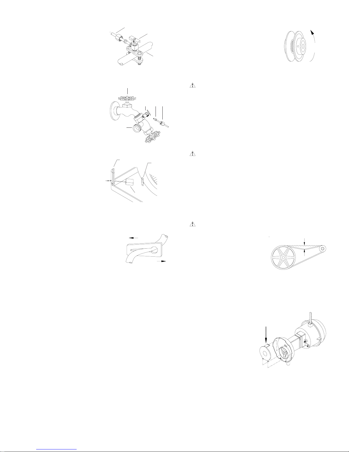
•Monte el motor. Instale el
motor del ventilador en las
horquillas de la montura.
Ajuste la horquilla ajustable
si es necesario y sujete el
motor con los seguros (véa-
se fig. 1).
¿CUANTO DEBE ABRIR LAS VENTANAS?
Un concepto a menudo entendido mal de enfriamiento por
evaporación es la cantidad de aire que debe ser agotada.
Cuánto debe usted abrir sus ventanas? El hecho es que la
mayoría de la gente no abre sus ventanas bastante. Los dos
métodos siguientes le ayudarán.
EL METODO PRIMERO
Usted debe dejar una abertura de dos pies cuadrados por
cada 1000 P.C.M. (pies cúbicos por minuto), según la capaci-
dad de su modelo. Ejemplo: Un Modelo 4000 SM de 2973
P.C.M. requiere 6 pies cuadrados (856 pulgadas cuadradas)
de abertura (2973/1000 * 2 = 6). Ahora, multiplique el número
de las ventanas por el ancho de las mismas; luego divida esta
cantidad entre el número de pulgadas cuadradas requeridas
para su unidad. El resultado le dice hasta qué altura hay que
abrir las ventanas. En este ejemplo, cuatro ventanas que
miden 36 pulgadas (0,9 m) de ancha se deben abrir 6 pulga-
das por cada una.
EL METODO DE EQUILIBRAR EL AIRE
1. Tome un pedazo de papel de seda y córtelo a lo largo en 3
tiras iguales.
2. Ponga en marcha a su enfriador a “High-Cool”.
3. Abra una ventana por lo menos seis pulgadas de ancho en
cada sitio que usted desee refrescar.
4. Tome un pedazo de papel de seda y póngalo contra la
pantalla de la ventana abierta más lejos de la apertura del
enfriador. Suéltalo al papel de seda. Hará una de tres
cosas:
SI: Se caiga.
ENTONCES: CIERRE todas las ventanas una pulgada e in-
tente el paso 4 otra vez.
SI: Se queda contra la pantalla con fuerza.
ENTONCES: ABRA todas las ventanas una pulgada e in-
tente el paso 4 otra vez.
SI: Se queda ligeramente contra la pantalla.
ENTONCES: PERFECTO. Se ha acabado. Goce del aire
refrescante.
NOTAS:
• Al poner el enfriador a “low-cool”, usted debe reequilibrar el
aire de su hogar. Repita el paso 4.
• Al equilibrar el aire de su hogar usted puede refrescar algu-
nas áreas más que otras abriendo esas ventanas más y
cerrando las otras por la misma cantidad. Repita el paso 4.
Asegurarse de que el aire de su hogar sea equilibrado.
SEGUROS
HORQUILLA
AJUSTABLE
FIG. 1

9
110520
CONECTAR EL AGUA
• Instale el montaje de desagüe. Quite la tuerca y pase la
boquilla por el agujero de la bandeja, colocando la arandela
de hule entre la bandeja y la cabeza de la boquilla (véase
fig. 5). Coloque la tuerca en la boquilla y atorníllela hasta
que quede apretada contra la parte inferior de la bandeja.
Inserte el tubo de desagüe en la
boquilla para retener el agua. El
tubo de desagüe se puede quitar
paradesaguar el agua de la ban-
deja cuando sea necesario. Se
puede conectar una manguera
de jardín a la boquilla para des-
aguar el agua hacia otra parte.
ARANDELA DE HULE
TUBO DE DESAGÜE
BOQUILLA ROSCADA
BANDEJA
TUERCA
FIG. 5
•Instale la polea del motor.
Instale la polea ajustable del
motor para que queda ali-
neada con la polea del
ventilador (véase fig. 2) y
apriete el tornillo.
TORNILLOS
FIG.3
CAJA DE
EMPALME
• Conecte el tubo de
abastecimiento de
agua. Encuentreelabas-
tecimiento de agua más
cercano. Utilice la válvu-
la de la montura (fig. 6)
para conectar la tubería
del cobre de 1/4 pulgada
con el abastecimiento de
agua fría de la casa, o utilice
una llave de paso y la válvula
de agua conectada con un gri-
fo exterior (fig. 7). Coloque la
tuerca y la férula en el tubo y
apriete bien la tuerca para im-
pedir que gotee el agua.
IMPORTANTE: No conecte el
abastecimiento de agua con nin-
guna aplicación de agua blanda.
Elaguablanda disminuirá la vida
del enfriador.
• Conecte el tubo de agua al
flotador. Conecte el tubo de
agua en la misma manera de
arriba. Puede instalar el flo-
tador en el poste de esquina o
en el soporte (fig. 8).
• Llene la bandeja con agua.
Permita que se llene la bandeja con agua hasta una altura
de una pulgada por debajo del borde superior de la bandeja
y ajuste el flotador para que mantenga este nivel. Esto se
puede lograr torciendo la varilla del flotador para arriba o
para abajo.
• Ajuste la cantidad de agua. Su enfriador viene equipado
con una válvula especial que mide el agua (fig. 9). La can-
tidad de agua que llega a los filtros puede ser disminuida
presionando la válvula de plástico en
el sentido indicado por las flechas.
Si el agua se desborda de los cana-
les, puede ser necesario disminuir el
flujo de agua. Revise y vea que to-
dos los filtros estén empapados de
aguay no tengan partes secaso agu-
jeros en los filtros.
INSTALACION ELECTRICA
ADVERTENCIA: Desconecte todos los servicios eléc-
tricos que serán usados en esta unidad antes de instalar
el enfriador.
•Quite la caja de empal-
me. Lacaja deempalme
se encuentra en el rin-
cón superior del interior
del enfriador. Quite los
dos tornillos de la caja y
deslice la caja hacia
abajo para tener acceso
al cableado (fig. 3).
•Conecte el cableado eléctrico. Las conexiones eléctricas
deben ser hechas por un electricista competente, para que
todo el cableado eléctrico cumpla con los requisitos esta-
blecidos para su localidad. Vea la figura 4 para el esquema
del cableado.
IMPORTANTE: Con un motor de una sola velocidad, no
use la línea roja en el cableado del enchufe y la clavija del
motor. Envuelva el extremo de ambas líneas rojas con cinta
eléctrica.
ADVERTENCIA: Compruebe que la caja del enfriador
tenga la debida conexión a tierra para proveer máxima
seguridad.
CAJA DE
LA RUEDA
POLEA
DEL
MOTOR
POLEA DEL
VENTILADOR
FIG. 2
AUMENTAR
DISMINUIR
FIG.9
LLAVE
VALVULA
DE AGUA
LLAVE DE
PASO
FERULA
TUERCA
FIG. 7
FLOTADOR
POSTE DE
ESQUINA SOPORTE
FIG. 8
ABASTECIMIENTO
DE AGUA FRIA
VALVULA DE
LA MONTURA
TUBERIA
DEL COBRE
FIG. 6
AMPERIO Y TENSION DE LA BANDA
Esta unidad viene equipada de una polea ajustable que per-
mite ajustar la velocidad del ventilador segun la capacidad
del motor en diferentes sistemas de conductos. Es importan-
te que la polea del motor sea ajustada al tamaño correcto,
paraasegurar el máximorendimiento sin dañar el motor. Siga
cuidadosamente estas instrucciones.
•Ajuste la polea del motor. Después de instalar el enfria-
dor completo, ajuste la polea al diámetro mínimo y ajuste la
tensión de la banda. Vea la sección de mantenimiento para
ajustar la polea.
•Poner en marcha la unidad. Instale todas las rejas con los
filtors,prendalabomba y permita que siga funcionando hasta
que todos los filtros estén mojados.
NEGRO
ROJO
VERDE
BLANCO
NEGRO/AZUL
ALTO
BAJO
COMUN
BOMBA
TIERRA
A INTERRUPTOR
BLANCO
VERDE
TIERRA 115 VOLTIOS
60 HZ
FIG. 4

10 110520
DISMINUIR
AMPERIO
FIG. 10
•Revise el amperio. Con los filtros mojados y la unidad en
funcionamiento, revise el amperio del motor con un medidor
de amperio.
•Ajuste la polea si es necessario. Si la lectura de amperio
es menos del valor especificado del motor, apague la uni-
dad y quite la reja con el filtro. Desconecte el motor dentro
de la caja para protegerse en caso de que alguien intente
poner en marcha el enfriador mientras usted está trabajan-
do. Esto hay que hacerlo por su propia seguridad. Ajuste la
polea a un diámetro mas grande y vuelva a ajustar la ten-
sión de la banda. Conecte el motor,
coloque la reja y compruebe de nue-
vo el amperio. Repita estos pasos
hasta obtener la lectura da amperio
correcta. El incrementar el diáme-
tro de la polea, incrementa también
el amperio; el disminuir el diámetro
de la polea, disminuye también el am-
perio (véase fig. 10).
PRECAUCION: No permita que funcione esta unidad
si toma mas amperio del que se indica la placa del motor.
NOTA: No se debe intentar la instalación completa de esta
unidad sin la ayuda de un electricista o alguien que sepa
medir el amperio. Si usted no sigue esta instrucción, podrá
ser anulada su garantía.
FIG. 12
3 LIBRAS
3/4 PULGADAS
APRIETE AQUI
PARA QUITAR
FIG.11
MANTENIMIENTO
ADVERTENCIA: Antes de hacer cualquier manteni-
miento, compruebe que la corriente esté apagada. Al
quitar una reja, desconecte el motor y la bomba dentro de
la caja. Esto es por su seguridad.
PUESTA EN MARCHA EN LA PRIMAVERA
•Cambie los filtros. Debe cambiar los filtros de paja una o
dos veces durante cada temporada, según la duración de
ésta. Al principio y a mediados de la temporada, un filtro
limpio es más absorbente y eficiente y producirá un mayor
volumen de aire frío.
•Limpie la bomba. Es necesario limpiar la bomba una vez
al principio de cada año. Por su propia seguridad, apague
la unidad y desconecte el motor y la bomba. Quite el sujeta-
dor de plástico de la montura y jale la bomba, deslizándola
hacia usted. Quite la parte de abajo según se muestra en la
figura 11. Limpie la bomba. Dé le vuelta a la hélice para
verificar que se mueve libremente. Quite el pico de la bom-
ba y vea si está obstruido. Vuelva a colocar la bomba en la
unidad y fíjela en su montura con el sujetador de plástico.
Esto impedirá que se
caiga la bomba al
agua,lo que dañaría el
motor. No se olvide de
volvera conectar el tubo
deagua a la bomba. La
bombacontiene protec-
ción en caso de
sobrecalentamiento (se
apagará automática-
mente).
•Lubrique los cojinetes. Los cojinetes de la rueda y el mo-
tor del ventilador deben ser lubricados usando unas gotas
de un aceite no detergente de densidad 20/30 una vez al
año. No obstante, los motores sin tuberías para aceite no
necesitan ser lubricados. Estos motores son lubricados en
la fábrica de por vida y no requieren nunca ninguna lubrica-
ción.
PRECAUCION: No lubrique demás. El agregar dema-
siadoaceite puede ocasionar quesequemeelmotor, a causa
del aceite entrando al interior del
motor.
•Compruebe la tensión de
la banda. Una fuerza de 3
libras debe desviar la ban-
da 3/4 pulgadas (véase fig.
12). Ajuste la banda si es
necesario.
PREPARAR LA UNIDAD PARA EL INVIERNO
•Drene el agua. Drene siempre toda el agua de la unidad y
del tubo de abastecimiento de agua cuando no use el en-
friador durante períodos prolongados, especialmente al fin
de la temporada. El tubo debe quedarse desconectado del
enfriador y del abastecimiento de agua para que no lo con-
gele.
•Desconecte el motor y la bomba. Cuando no se utiliza el
enfriador por períodos extendidos, desconecte el motor y la
bomba dentro del enfriador.
•Cubra la unidad. Para proteger y alargar la vida útil del
acabado, se sugiere cubrir el enfriador durante períodos lar-
gos cuando no sea utilizado.
Siusted sigue estas sugerencias encuantoa instalación, ope-
ración y mantenimiento, podrá disfrutar de muchos años de
servicio eficiente y satisfactorio de este enfriador. Si desea
más información, su concesionario tendrá mucho gusto en
ayudarle con respecto a cualquier duda o pregunta.

11
110520
1. No llega corriente
• Fusible fundido
• Cortacircuito desactivado
• Cable eléctrico dañado
2. Banda muy floja o apretada
3. Motor recalentado
• Banda muy apretada
• Cojinetes de la rueda están secos
• Diámetro de la polea del motor
demasiado grande
4. Motor parado
1. Insuficiente abertura para que salga el
aire
2. Poca tensión en la banda
3. Filtros obstruidos
4. Agua insuficiente en los filtros
1. El agotamiento del aire es inadecuado
2. Los filtros no están mojados
• Filtros obstruidos
• Filtros agujereados
• Agujeros de los canales obstruidos
• Bomba no funciona
1. Voltaje deficiente
2. Demasiada tensión en la banda
3. Eje del ventilador atorado
4. Cojinetes secos
5. Diámetro de la polea del motor
demasiado grande dando por resultado
sobrecarga del motor
1. Cojinetes secos
2. Rueda roza contra caja de la rueda
3. Partes sueltas
1. Insuficiente salida de aire
1. Agua estancado en la unidad
2. Los filtros tienen moho o son obstrui-
dos.
3. Los filtros son secos
• Agujeros del canal tapados
• Bomba no trabaja adecuada
1. El flotador no se ajusta correctamente
2. El montaje de desagüe se está
escapando
1. Revise la corriente
• Cambie el fusible
• Restablecer el cortacircuito
• Reemplace el cable
2. Ajuste la tensión de la banda
3. Determine la causa
• Ajuste la tensión de la banda
• Lubrique los cojinetes
• Ajústela al diámetro correcto
4. Cambie el motor
1. Abra las ventanas o las puertas para aumen-
tar el flujo de aire
2. Ajuste la tensión o cambie la banda
3. Cambie los filtros
4. Limpie el sistema de distribución y los
agujeros del canal
1. Abra más las ventanas o puertas
2. Revise la distribución de agua
• Cambie los filtros
• Acomode la paja en el filtro
• Límpielos
• Cámbiela o límpiela (Desconecte la unidad)
1. Compruebe el voltaje
2. Ajuste la tensión de la banda
3. Lubrique o cambie los cojinetes (Desconecte
la unidad)
4. Lubrique los cojinetes
5. Ajuste la polea para no exceder el grado a
carga plena del amperio del motor
1. Lubrique los cojinetes
2. Inspeccione y alinee (Desconecte la unidad)
3. Apriételas
1. Abra las puertas o las ventanas
1. Desagüe y limpie los filtros
2. Cambie los filtros
3. Revise la distribución de agua
• Límpielos
• Reemplace o limpie la bomba (Desconecte
la unidad)
1. Ajuste el flotador
2. Apriete la tuerca y el tubo de desagüe
PROBLEMA CAUSA POSIBLE REMEDIO
LA LOCALIZACION DE AVERIAS
No arranca o no sale
aire
Sale poco aire
cuando la unidad está
funcionando
Enfriamiento inade-
cuado
Motor se apaga y se
enciende
Hace Ruido
Demasiada humedad
en la casa
Olor a encerrado, olor
desagradable
El agua está drenando
sobre el tejado.

12 110520
GARANTIA LIMITADA
La presente garantía se extiende al comprador original de un enfriador evaporativo instalado y utilizado bajo condiciones
normales. No cubre daños ocurridos por accidente, descuido o abuso por parte del propietario. No autorizamos que ninguna
otra persona o representante asuma por nosotros cualquier otra o diferente responsabilidad en relación con este producto.
TERMINOS Y CONDICIONES DE LA GARANTIA
Durante Ocho Años a partir de la fecha de instalación, nosotros reemplazaremos la base original del enfriador en caso de que
goteara agua debido a oxidación.
DuranteUnAñoapartir de la fecha de instalación, reemplazaremos cualquier componenteoriginalproporcionadoporChampion
Cooler Corporation que falle debido a cualquier defecto de material o mano de obra en la fábrica solamente.
EXCLUSIONES DE LA GARANTIA
No somos responsables por reemplazar los filtros del enfriador. Estos son componentes desechables y deben cambiarse
periódicamente. No somos responsables por daños que resulten a consecuencia de alguna falla de funcionamiento.
No somos responsables por cualquier daño producido por el uso de suavizadores de agua, productos químicos, materiales
desincrustantes, envolturas de plástico, o si se usa en esta unidad un motor de mayor potencia de la que se indica en la placa
de número de serie.
No somos responsables por el costo del servicio por diagnosticar la causa del problema ni por la mano de obra necesaria para
reparar y/o reemplazar partes.
COMO OBTENER SERVICIO BAJO ESTA GARANTIA
Póngase en contacto con el Concesionario que le vendió el enfriador. Si por alguna razón usted no queda satisfecho con la
respuestapor parte del Concesionario, comuníqueseconel departamento de servicio alcliente: ChampionCooler Corporation,
ESTA GARANTIA LIMITADA SE APLICA AL COMPRADOR ORIGINAL SOLAMENTE
This manual suits for next models
4
Table of contents
Languages:
Other Marquis Freezer manuals
Popular Freezer manuals by other brands

Miele
Miele KFN 8701 SE ed-1 Operating and installation instructions

Husky
Husky HUS-CN161 owner's manual

Zanussi
Zanussi ZFT10210WA user manual

NABO
NABO GN 1752 user manual

GEAppliances
GEAppliances FCM5 Owner's Manual & Installation Instructions

Thermo Scientific
Thermo Scientific TSX Series Installation and operation