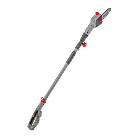
MasterCraft 054-0370-0 User manual

IMPORTANT:
Read and understand this instruction manual
thoroughly before using the product.
INSTRUCTION
MANUAL
8” (20 CM) POLE SAW
054-0370-0

headline bars
continuation tabs
notes
warnings
headline bars
continuation tabs
notes
warnings
headline bars
continuation tabs
notes
warnings

headline bars
continuation tabs
notes
warnings
headline bars
continuation tabs
notes
warnings
headline bars
continuation tabs
notes
warnings
3
TABLE OF CONTENTS
Technical Specifications 4
Safety Guidelines 5
Key Parts Diagram 9
Operating Instructions 11
Maintenance 18
Troubleshooting 22
Parts List 23
Warranty 26
NOTE:
If any parts are missing or damaged, or if you have any questions, please
call our toll-free helpline at 1-800-689-9928.
SAVE THESE INSTRUCTIONS
• This manual contains important safety and operating instructions. Read all
instructions and follow them with use of this product.
TABLE OF CONTENTS

headline bars
continuation tabs
notes
warnings
headline bars
continuation tabs
notes
warnings
headline bars
continuation tabs
notes
warnings
model no. 054-0370-0 | contact us 1-800-689-9928
4
TECHNICAL SPECIFICATIONS
Rated Voltage 20 V d.c. max*
Guide Bar Length 8’’ (20 cm)
*Maximum battery voltage without workload; with workload nominal voltage is 18 V.

headline bars
continuation tabs
notes
warnings
headline bars
continuation tabs
notes
warnings
headline bars
continuation tabs
notes
warnings
5
SAFETY GUIDELINES:
WARNING!
Safety symbols in this Instruction Manual are used to flag possible dangers. The safety
symbols and their explanations require your full understanding. The safety warnings do
not, by themselves, eliminate any danger, nor are they substitutes for proper accident
prevention measures.
WARNING!
This Safety Alert Symbol indicates caution, warning, or danger. Failure to obey a safety
warning can result in serious injury to yourself or others. To reduce the risk of injury, fire,
or electric shock, always follow the safety precautions.
KNOW YOUR TOOL
To operate this tool, carefully read this Instruction Manual and all labels affixed to the pole saw before
using. Keep this instruction manual available for future reference.
IMPORTANT
This tool should only be serviced by a qualified service technician. For more information, call the toll free
helpline at 1-800-689-9928.
GENERAL POWER TOOL SAFETY WARNINGS
INSTRUCTIONS PERTAINING TO A RISK OF FIRE, ELECTRIC SHOCK, OR INJURY
TO PERSONS
WARNING!
When using electric gardening appliances, basic safety precautions should always be
followed to reduce the risk of fire, electric shock, and personal injury.
READ ALL INSTRUCTIONS THOROUGHLY.
WARNING!
Do not operate near electrical power lines. The unit has not been designed to provide
protection from electric shock in the event of contact with overhead electric lines. Consult
local regulations for safe distances from overhead electric power lines and ensure that the
operating position is safe and secure before operating the pole saw.
WARNING!
Wear appropriate personal hearing protection during use. Under some conditions and
durations of use, noise from this product may contribute to hearing loss.
• Avoid dangerous environment. Don’t use appliances in damp or wet locations.
• Don’t use in rain.
SAFETY GUIDELINES

headline bars
continuation tabs
notes
warnings
headline bars
continuation tabs
notes
warnings
headline bars
continuation tabs
notes
warnings
6
model no. 054-0370-0 | contact us 1-800-689-9928
SAFETY GUIDELINES
• Keep children away. All visitors should be kept at a distance away from work area.
• Dress properly. Do not wear loose clothing or jewellery. They can be caught in moving parts.
Use of rubber gloves and substantial footwear is recommended when working outdoors. Wear
protective hair covering to contain long hair.
• Use safety glasses. Always use face or dust mask if operation is dusty.
• Use right appliance. Do not use appliance for any job except that for which it is intended.
• Don’t grasp the exposed cutting blades or cutting edges when picking up or holding
the appliance.
• Don’t force appliance. It will do the job better and with less likelihood of a risk of injury at the
rate for which it was designed.
• Don’t overreach. Keep proper footing and balance at all times.
• Stay alert. Watch what you are doing. Use common sense. Do not operate appliance when you
are tired.
• Keep all parts of the body away from the saw chain. Do not remove cut material or hold
material to be cut when blades are moving. Make sure the switch is off when clearing jammed
material. Saw chain continues to move after the switch is turned off. A moment of inattention
while operating the pole saw may result in serious personal injury.
• Carry the pole saw by the handle with the saw chain stopped. When transporting or
storing the pole saw, always fit the saw chain device cover. Proper handling of the pole saw will
reduce possible personal injury from the saw chain.
• Hold the pole saw by insulated gripping surfaces only because the saw chain may
contact hidden wiring. A saw chain contacting a “live” wire may make exposed metal parts of
the pole saw “live” and could give the operator an electric shock.
• Do not use the pole saw in bad weather conditions, especially when there is a risk of
lightning. This decreases the risk of being struck by lightning.
• To reduce the risk of electrocution, never use near any electrical power lines. Contact
with or use near power lines may cause serious injury or electric shock resulting in death.
• Always use two hands when operating the pole saw. Hold the pole saw with both hands to
avoid loss of control.
• Always use head protection when operating the pole saw overhead. Falling debris can
result in serious personal injury.
• Store idle appliances indoors. When not in use, appliances should be stored indoors in a dry
and high or locked-up place with the battery pack removed−out of reach of children.
• Maintain appliance with care. Keep cutting edge sharp and clean for best performance and
to reduce the risk of injury. Follow instructions for lubricating and changing accessories. Keep
handles dry, clean, and free from oil and grease.

headline bars
continuation tabs
notes
warnings
headline bars
continuation tabs
notes
warnings
headline bars
continuation tabs
notes
warnings
7
SAFETY GUIDELINES
• Check damaged parts. Before further use of the product, a guard or other part that is damaged
should be carefully checked to determine that it will operate properly and perform its intended
function. Check for alignment of moving parts, binding of moving parts, breakage of parts,
mounting, and any other condition that may affect the tool’s operation. A guard or other part
that is damaged should be properly repaired or replaced by an authorized service centre unless
indicated elsewhere in this manual.
• Prevent unintentional starting. Ensure the switch is in the off-position before connecting to
battery pack, picking up or carrying the appliance. Carrying the appliance with your finger on the
switch or energizing appliance that have the switch on invites accidents.
• Disconnect the battery pack from the appliance before making any adjustments,
changing accessories, or storing appliance. Such preventive safety measures reduce the
risk of starting the appliance accidentally.
• Recharge only with the charger specified by the manufacturer. A charger that is suitable
for one type of battery pack may create a risk of fire when used with another battery pack.
• Use appliances only with specifically designated battery packs. Use of any other battery
packs may create a risk of injury and fire.
• When battery pack is not in use, keep it away from other metal objects, like paper clips, coins,
keys, nails, screws or other small metal objects, that can make a connection from one terminal to
another. Shorting the battery terminals together may cause burns or a fire.
• Under abusive conditions, liquid may be ejected from the battery; avoid contact. If contact
accidentally occurs, flush with water. If liquid contacts eyes, additionally seek medical help.
• Liquid ejected from the battery may cause irritation or burns.
• Do not use a battery pack or appliance that is damaged or modified. Damaged or modified
batteries may exhibit unpredictable behavior resulting in fire, explosion or risk of injury.
• Do not expose a battery pack or appliance to fire or excessive temperature. Exposure to fire or
temperature above 130°C (265°F) may cause an explosion.
• Follow all charging instructions and do not charge the battery pack or appliance outside of the
temperature range specified in the instructions. Charging improperly or at temperatures outside
of the specified range may damage the battery and increase the risk of fire.
• Have servicing performed by a qualified repair person using only identical replacement parts. This
will ensure that the safety of the product is maintained.
• Do not modify or attempt to repair the appliance or the battery pack (as applicable) except as
indicated in the instructions for use and care.
SAVE THESE INSTRUCTIONS.

headline bars
continuation tabs
notes
warnings
headline bars
continuation tabs
notes
warnings
headline bars
continuation tabs
notes
warnings
headline bars
continuation tabs
notes
warnings
headline bars
continuation tabs
notes
warnings
headline bars
continuation tabs
notes
warnings
8
model no. 054-0370-0 | contact us 1-800-689-9928
SAFETY GUIDELINES
ADDITIONAL SAFETY GUIDELINES
• The label on your tool may include the following symbols. The symbols and their definitions are as
follows:
V ..................... Volts
A ..................... Amperes
min ................. Minutes
or d.c .............. Direct current
n0……………….......No-load speed
…/min or …min-1…...Revolutions or reciprocations per minute
E490727
........................The logo of UL certification.
.............. WARNING–To reduce the risk of injury, user must read instruction manual.
.............. WARNING–To reduce the risk of injury, always wear eye protection.
.............. WARNING–To reduce the risk of injury, always wear ear protection.
............... WARNING–Wear head protection.
.............. WARNING–Keep sufficient distance away from electrical power lines.
.............. WARNING–Wear protective gloves.
.............. WARNING–Wear safety footwear.
WARNING!
To reduce the risk of electric shock or damage to the charger and battery, use only the
Mastercraft®batteries and chargers listed.
BATTERY PACK CHARGER
054-3124-0, 054-7553-4,
054-7557-6, 054-2434-8
054-3126-6,
054-7559-2
• For best results, your battery and tool should be charged, stored and used in a location
where the temperature is more than 5°C (41°F) but less than 40°C (104°F). Do not store
outside or in vehicles.

headline bars
continuation tabs
notes
warnings
headline bars
continuation tabs
notes
warnings
headline bars
continuation tabs
notes
warnings
9
headline bars
continuation tabs
notes
warnings
headline bars
continuation tabs
notes
warnings
headline bars
continuation tabs
notes
warnings
PACKAGE CONTENTS:
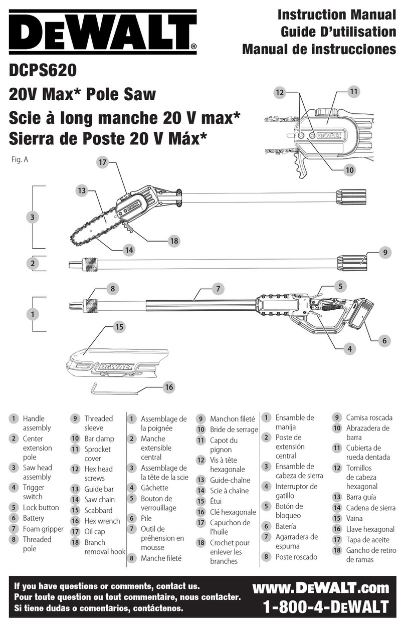
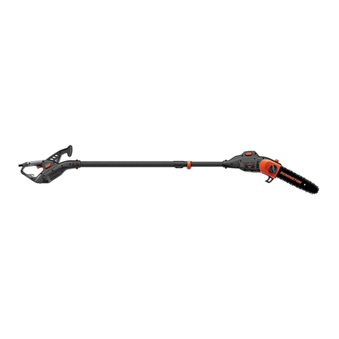
Pole saw, saw chain, guide bar, strap, chain sheath, wrench and instruction manual
KEY PARTS DIAGRAM
12345
11
19 18 15 14 13 1216
17
20
10
6 7
8
9
KEY PARTS DIAGRAM

headline bars
continuation tabs
notes
warnings
headline bars
continuation tabs
notes
warnings
headline bars
continuation tabs
notes
warnings
headline bars
continuation tabs
notes
warnings
headline bars
continuation tabs
notes
warnings
headline bars
continuation tabs
notes
warnings
10
model no. 054-0370-0 | contact us 1-800-689-9928
KEY PARTS DIAGRAM
No. Description No. Description
1 Guide bar 11 Threaded sleeve
2 Saw chain 12 Threaded connection
3 Oil tank cap 13 Screw sleeve
4 Side cover 14 Rear pole
5 Front pole 15 Foam handle
6 Threaded sleeve 16 Strap hole
7 Side-cover knob 17 Lock-off button
8 Chain sheath 18 Trigger switch
9 Threaded connection 19 Rear handle
10 Extension pole 20 On-board wrench
WARNING!
• Remove the pole saw from the package and examine it carefully. Do not discard the carton or any
packaging material until all parts have been examined.
• If any part of the pole saw is missing or damaged, do not attach the tool to a power source or use the tool
until the part has been repaired or replaced. Failure to heed this warning could result in serious injury.
• Do not allow familiarity with the pole saw to cause a lack of alertness. A fraction of a second of
carelessness is enough to cause severe injury.
FPO

headline bars
continuation tabs
notes
warnings
headline bars
continuation tabs
notes
warnings
headline bars
continuation tabs
notes
warnings
11
headline bars
continuation tabs
notes
warnings
headline bars
continuation tabs
notes
warnings
headline bars
continuation tabs
notes
warnings
OPERATING INSTRUCTIONS
INSTALL THE GUIDE BAR AND CHAIN
(
fig. 1
)
1. Rotate the side-cover knob counter-clockwise and
then remove the side cover (fig. 1a).
2. Lay the new saw chain in a loop on a flat surface and
straighten any kinks. The cutter should face in the
direction of chain rotation; if they face backwards,
turn the loop over (fig. 1b). The direction of the cutter
should be in consistent with the directions marked on
the guide bar and the enclosure.
3. Place the chain drive links into the guide bar groove.
Position the chain so there is a loop at the back of the
guide bar (fig. 1c).
4. Hold the chain in position on the bar and place the
loop around the sprocket. Fit the bar against the
mounting surface so that the bar stud is in the long
slot of the bar and the adjusting pin is in the chain-
tension pin hole (fig. 1d).
OPERATING INSTRUCTIONS
fig. 1a Side-cover knob
Side cover
fig. 1b
Chain rotation
Chain drive link
Cutter
fig. 1c
Loop
fig. 1d
Bar stud
Sprocket
Chain-tension pin hole Adjusting pin

headline bars
continuation tabs
notes
warnings
headline bars
continuation tabs
notes
warnings
headline bars
continuation tabs
notes
warnings
12
model no. 054-0370-0 | contact us 1-800-689-9928
5. Replace the side cover onto the saw head. Rotate
the side-cover knob clockwise to slightly tighten the
side cover, but leave the bar free to move for tension
adjustment (fig. 1e).
6. Rotate the side-cover knob clockwise to completely
tighten the side cover.
fig. 1e
Side-cover knob
Side cover
OPERATING INSTRUCTIONS
WARNING!
• Always wear protective gloves when handling the bar and chain; these components are sharp and may
contain burrs.
FPO
NOTICE:
• When you first purchase your pole saw, the chain and bar will not be attached to the saw.
• The chain is correctly tensioned when there is no sag on the underside of the guide bar; the chain is snug, but can be
rotated by hand without binding. For more information on chain tensioning, see the maintenance section.
• If the chain is too tight, it will not rotate. Loosen the side cover slightly and turn the chain tensioner 1/4 turn counter-
clockwise (fig. 1f).Lift the tip of the guide bar up and retighten the side cover. Ensure that the chain can be rotated by
hand without binding.
fig. 1f
Chain tensioner
Loosen the chain tension
Wrench

headline bars
continuation tabs
notes
warnings
headline bars
continuation tabs
notes
warnings
headline bars
continuation tabs
notes
warnings
13
OPERATING INSTRUCTIONS
CONNECT THE POLES (
fig. 2
)
ATTACH WITHOUT THE EXTENSION POLE
(
fig. 2a
)
1. Remove the battery pack.
2. Align the rib on the front pole with the arrow slot on
the rear pole and push the front pole into the rear
pole.
3. Rotate the threaded sleeve to the thread on the
threaded connection securely.
4. Pull on the front pole to verify that it is securely locked in place.
ATTACH WITH THE EXTENSION POLE (
fig. 2b
)
The extension pole extends the cutting range. It should be connected between the front pole and the
rear pole.
Follow the previous instructions to connect the front pole to one end of the extension pole, and then
connect the rear pole to the other end of the extension pole the same way.
NOTICE:
• Do not grasp the screw sleeve during operation.
FPO
WARNING!
• Never attach or adjust the pole assembly with the battery installed. Failure to stop the motor and remove
the battery may cause serious personal injury. It’s also recommended to attach the chain sheath when
handling the pole assembly.
• Be certain that the threaded sleeve is fully tightened before operating the tool; check it periodically for
tightness during use to avoid serious personal injury.
fig. 2a
Arrow slotRib
Front pole Threaded
sleeve
Threaded
connection
Rear pole
Screw sleeve
fig. 2b
Rear pole Extension pole Front pole

headline bars
continuation tabs
notes
warnings
headline bars
continuation tabs
notes
warnings
headline bars
continuation tabs
notes
warnings
14
model no. 054-0370-0 | contact us 1-800-689-9928
ATTACH THE SHOULDER STRAP (
fig. 3
)
1. If needed, attach the shoulder strap to the bracket on
the rear pole with the carabiner hook.
2. Adjust the length of the strap to attain a comfortable
working position.
FILLING OIL TANK WITH BAR AND CHAIN
LUBRICANT (
fig. 4
)
The pole saw is not filled with oil at the time of
purchase. It is essential to fill the tank with oil before
use. Operating the pole saw without chain oil or when the oil level is below the minimum mark will
result in damage to the saw. Chain life and cutting
capacity depend on optimum lubrication. The chain
is automatically lubricated with chain oil from the
tank during operation.
1. Remove the battery pack from the pole saw.
2. Clean the oil tank cap and the area around it to
ensure that no dirt falls into the oil tank.
3. Position the pole saw on its side on a firm, flat
surface, so that the oil tank cap is facing upwards.
Rotate the oil tank cap counter-clockwise to remove
it.
4. Carefully pour the oil into the tank. Fill to the bottom of the fill neck. Wipe off any excess oil.
5. Replace the cap, place the saw upright, and view the level through the oil inspection window. Oil should fill
the window.
fig. 4 Oil tank cap
Oil tank
OPERATING INSTRUCTIONS
WARNING!
• Do not smoke or bring any fire or flame near the oil or the saw. Oil may spill and cause a fire.
FPO
NOTICE:
• Never use oil or other lubricants not specifically designed for use on the bar and chain. This can lead to a clogged oil
system, which may cause premature wear of the bar and chain.
• Check the oil level frequently and fill when the oil level falls below the minimum line. Never operate the pole saw if the oil
is not visible.
• Do not use dirty, used, or otherwise contaminated oil. Damage may occur to the bar or chain.
• It is normal for oil to seep from the saw when it is not in use. To prevent seepage, empty the oil tank after each use, and
then run the saw for one minute. When storing the tool for a long period of time, be sure the chain is lightly lubricated; this
will prevent rust on the chain and bar sprocket.
fig. 3
Bracket
Carabiner hook

headline bars
continuation tabs
notes
warnings
headline bars
continuation tabs
notes
warnings
headline bars
continuation tabs
notes
warnings
15
TO ATTACH THE BATTERY (
fig. 5
)
1. Make sure that the sander is switched off.
2. Align the raised rib on the battery pack with the
grooves on the pole saw, and then slide the battery
pack onto the pole saw.
TO DETACH THE BATTERY (
fig. 5
)
1. Make sure that the pole saw is switched off.
2. Depress the battery-release button located on the
front of the battery pack to release the battery pack.
3. Pull the battery pack out and remove it from the pole saw.
START/STOP THE TOOL (
fig. 6
)
1. To turn the saw on, grasp the foam and rear handles
firmly, using both hands.
2. Press the lock-off button, and then squeeze the
trigger switch.
3. To turn the saw off, release the trigger switch and
allow the chain to come to a complete stop.
OPERATING INSTRUCTIONS
FPO
WARNING!
• Make sure that no objects or obstructions are in the immediate vicinity and could come in contact with
the bar and chain.
fig. 5
Battery-release button
fig. 6
Lock-off button
Trigger switch

headline bars
continuation tabs
notes
warnings
headline bars
continuation tabs
notes
warnings
headline bars
continuation tabs
notes
warnings
16
model no. 054-0370-0 | contact us 1-800-689-9928
BASIC CUTTING (
fig. 7
)
1. Take the proper stance in front of the tree with the
saw off. The most typical cutting application is to
position the unit at an angle of 60° or less depending
on the specific situation. As the angle of the pole saw
shaft to the ground increases, the difficulty of making
the first cut increases.
2. Start the tool to make a shallow first cut (1/4 of the
limb diameter) on the underside of the limb, close to
the main limb or trunk.
3. Make a second cut from the top side of the limb,
outboard from the first cut. Continue the cut through
the limb until the limb separates from the tree. Be
prepared to balance the weight of the tool when the
limb falls.
4. Make a final cut close to trunk.
5. Release the trigger switch as soon as the cut is
completed.
fig. 7a
OPERATING INSTRUCTIONS
• Never cut near power lines, electric cords, or other electric sources. If the bar and chain jams on any
electrical cord or line, DO NOT TOUCH THE BAR, CHAIN OR THE ALUMINUM POLE! THEY CAN BECOME
ELECTRICALLY LIVE AND MAY BE VERY DANGEROUS. Continue to hold the pole saw by the insulated
rear handle or lay it down and away from you in a safe manner. Disconnect the electrical service to the
damaged line or cord before attempting to free the bar and chain from the line or cord. Contact with the
bar, chain, other conductive parts of the pole saw, or live electric cords or lines will result in death by
electrocution or serious injury.
FPO
NOTICE:
• Practice cutting a few small logs to get the “feel” of using your saw before you begin a major sawing operation.
• For second and final cuts (from the top of the limb or branch), hold the bucking spikes against the limb being cut
(fig. 7c). This will help to steady the limb and make it easier to cut. Allow the chain to cut for you; exert only light,
downward pressure. If you force the cut, damage to the bar, chain, or motor can result.
fig. 7b LOAD
Second cut
First cut
Final cut
fig. 7c
Bucking spikes

headline bars
continuation tabs
notes
warnings
headline bars
continuation tabs
notes
warnings
headline bars
continuation tabs
notes
warnings
17
LIMBING AND PRUNING (
fig. 8
)
This pole saw is designed for trimming
small branches and limbs up to 8” (20 cm)
in diameter. For best results, observe the
following precautions.
1. Plan the cut carefully. Be aware of the
direction in which the branch will fall.
2. Remove long branches in several stages.
3. Cut lower branches first to allow the top
branches more room to fall.
4. Work slowly, keeping both hands on the saw with a firm grip. Maintain secure footing and balance.
5. Keep the tree between you and the chain while limbing. Cut from the side of the tree opposite the
branch you are cutting.
6. Do not make a flush cut next to the main limb or trunk until you have cut off much of limb to reduce
the weight.
7. To prevent electrocution, do not operate within 50’ (15 m) of overhead electrical lines.
8. Keep bystanders at least 50’ (15 m) away.
OPERATING INSTRUCTIONS
50’
(15 m)
fig. 8 Minimum
50’ (15 m)

headline bars
continuation tabs
notes
warnings
headline bars
continuation tabs
notes
warnings
headline bars
continuation tabs
notes
warnings
headline bars
continuation tabs
notes
warnings
headline bars
continuation tabs
notes
warnings
headline bars
continuation tabs
notes
warnings
model no. 054-0370-0 | contact us 1-800-689-9928
18
MAINTENANCE
CLEANING
1. After each use, clean debris from the chain and guide bar with a soft brush. Wipe the pole saw surface with
a clean cloth moistened with a mild soap solution.
2. Remove the side cover, and then use a soft brush to remove debris from the guide bar, saw chain, sprocket
and side cover.
3. Always clean out wood chips, saw dust, and dirt from the guide-bar groove when replacing the saw chain.
ADJUST THE CHAIN TENSION (
fig. 9
)
1. Stop the saw and remove the battery pack before
adjusting the chain tension.
2. Loosen the side-cover knob, insert the wrench into
the chain tensioner to adjust the guide bar and
retighten the side-cover knob securely. Ensure that
the chain will rotate without binding.
• During normal saw operation, the temperature
of the chain will increase. The drive links of
a correctly tensioned warm chain will hang
approximately 3/64’’ (1.3 mm) out of the bar
groove.
• A cold chain is correctly tensioned when there
is no slack on the underside of the guide bar
and the chain is snug, but it can be turned by
hand without binding. The chain must be re-
tensioned whenever the flats on the drive links
do not sit in the bar groove.
MAINTENANCE
NOTICE:
• New chains tend to stretch; check chain tension frequently.
• A chain tensioned while it is warm may be too tight upon cooling. Check the cold tension before next use.
fig. 9a
3/64” (1.3 mm)
fig. 9b
Flats on drive link

headline bars
continuation tabs
notes
warnings
headline bars
continuation tabs
notes
warnings
headline bars
continuation tabs
notes
warnings
19
headline bars
continuation tabs
notes
warnings
headline bars
continuation tabs
notes
warnings
headline bars
continuation tabs
notes
warnings
CHAIN MAINTENANCE
SHARPEN THE CUTTERS
(fig. 10a−fig. 10d
)
Be careful to file all cutters (fig. 10a) to the specified
angles and to the same length, as fast cutting can be
obtained only when all cutters are uniform.
1. Remove the battery pack. Wear gloves for protection.
2. Use a 5/32” (4.0 mm) diameter round file and holder
(available separately). Do all of your filing at the
middle position of the guide bar.
3. Keep the file level with the top plate of the tooth. Do
not let the file dip or rock.
4. Keep a correct sharpening angle of 30° between the
file and the saw chain; see figures 10b and 10c.
Always use a file holder (available separately) when
sharpening saw chains by hand. File holders have
markings for the sharpening angle.
5. Using light but firm pressure, stroke towards the front
corner of the tooth. Lift the file away from the steel on
each return stroke.
6. Make a few firm strokes on every tooth. File all left-hand cutters in one direction. Then move to the other
side and file the right-hand cutters in the opposite direction. Occasionally remove filings from the file with a
wire brush (fig. 10d).
fig. 10a
Depth gauge
Side plate
Top plate
MAINTENANCE
fig. 10c
FPO
WARNING!
• Improper chain sharpening increases the potential of kickback.
• Failure to replace or repair a damaged chain can cause serious injury.
fig. 10d
Left-hand cutters Right-hand cutters
fig. 10b
Filing
direction
Sharpening
angle: 30°
Cutter tooth
5/32”(4.0 mm)
round file

headline bars
continuation tabs
notes
warnings
headline bars
continuation tabs
notes
warnings
headline bars
continuation tabs
notes
warnings
20
model no. 054-0370-0 | contact us 1-800-689-9928
TOP-PLATE SHARPENING ANGLES
(
fig. 10e
)
CORRECT 30°- This optimal angle can be obtained
only when the specified files and proper setting are
used. File holders are marked with guide marks to
align the file properly to produce the correct top-plate
angle.
LESS THAN 30°- The tooth is too dull for cutting.
MORE THAN 30°- The edge of the cutting tooth is
feathered and dulls quickly.
SIDE-PLATE ANGLE (
fig. 10f
)
CORRECT 55°- The optimal angle can be produced
automatically if the correct diameter file is used in
the file holder.
HOOK- “Grabs” and dulls quickly. Increases potential
of KICKBACK. Results from using a file with a diam-
eter that is too small, or a file held too low.
BACKWARD SLOPE- Needs too much feed pressure,
causes excessive wear to bar and chain. Results from
using a file with a diameter too large, or a file held
too high.
DEPTH-GAUGE CLEARANCE
(
fig. 10g−fig. 10h
)
1. The depth gauge should be maintained at a
clearance of 1/32” (0.6 mm), as shown in fig. 10g.
Use a depth-gauge tool (available separately) to
check the depth-gauge clearances.
2. Check the depth-gauge clearance every time the
chain is filed.
Use a flat file and a depth-gauge jointer (both
available separately) to lower all gauges uniformly
(fig. 10h). Use a 1/32” (0.6 mm) depth-gauge jointer.
Depth gauges must be adjusted with the flat file in
the same direction that the adjoining cutter was filed
with the round file. Use care not to contact the cutter
face with the flat file when adjusting depth gauges.
MAINTENANCE
30°
fig. 10e
Correct
Top-plate sharpening angles
Less than 30° More than 30°
Incorrect Incorrect
fig. 10f
55°
Correct Incorrect Incorrect
Side-plate angle
Hook Backward Slope
fig. 10g
Depth-gauge clearance
1/32’’ (0.6 mm)
fig. 10h
Depth-gauge jointer
Flat file
Table of contents