matev MOW-H 160 CM Installation instructions

matev GmbH
Nürnberger Str. 50
90579 Langenzenn, Germany
T +49 9101 9087 -0
F +49 9101 9087 -20
www.matev.eu
Version 09/2017
Original Operating Manual
MOW-H/M 160 CM Combination Mower

Contents
Page 2
Table of contents
1 About this operating manual ................................................................................................................... 3
2 Safety ......................................................................................................................................................... 4
2.1 Intended use ............................................................................................................................................... 4
2.2 Qualifications of personnel ......................................................................................................................... 4
2.3 General safety notices ................................................................................................................................ 5
2.4 Special safety notices ................................................................................................................................. 5
2.5 Basic rules .................................................................................................................................................. 7
3 Task and use ............................................................................................................................................. 8
3.1 Task ............................................................................................................................................................ 8
3.2 Function ...................................................................................................................................................... 8
3.3 General instructions for mowing ................................................................................................................. 8
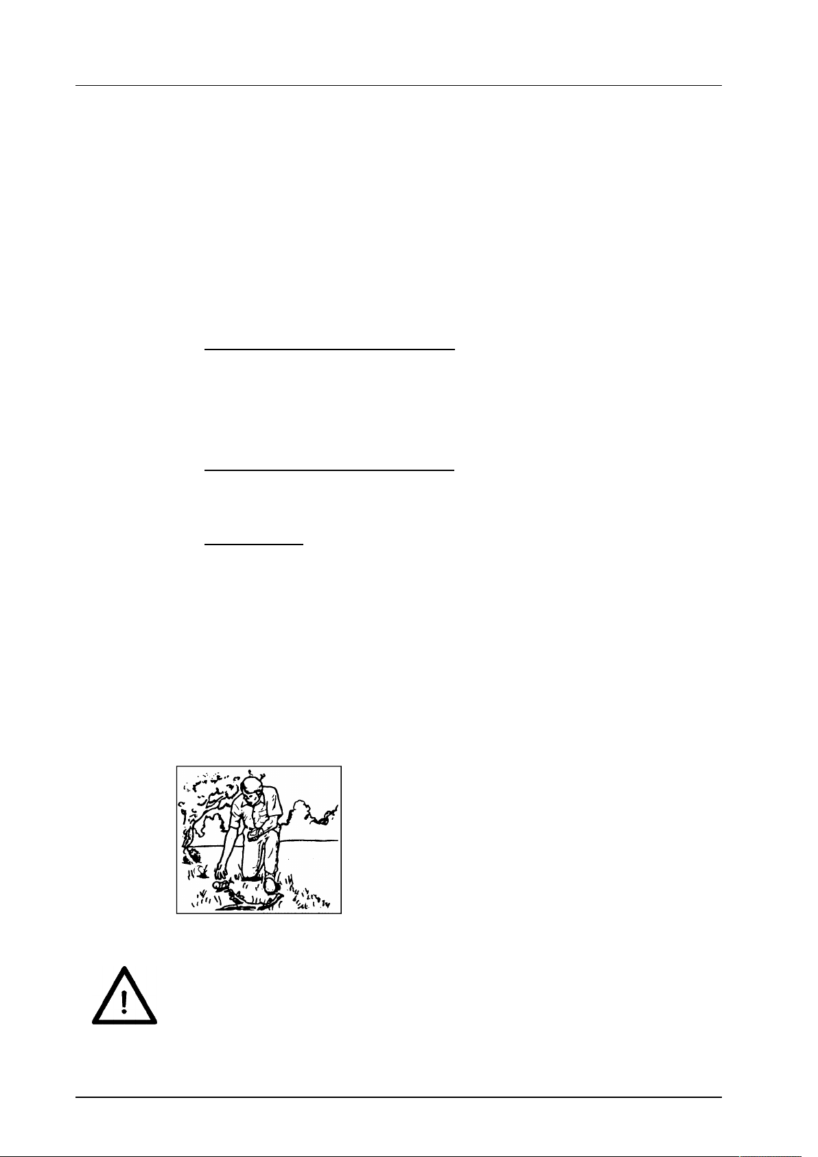
3.3.1 Clean the work terrain before mowing ........................................................................................................ 8
3.3.2 Mowing irregular areas ............................................................................................................................... 9
3.3.3 Mowing large areas .................................................................................................................................... 9
3.3.4 Mowing small areas .................................................................................................................................... 9
4 Delivery and transport ........................................................................................................................... 10
5 Mounting the implement ........................................................................................................................ 10
5.1 Mounting the front mower on the carrier vehicle ....................................................................................... 11
5.2 Mowers with mechanical drive .................................................................................................................. 11
5.2.1 Mounting the universal joint shaft ............................................................................................................. 13
5.2.2 Dismounting the PTO shaft....................................................................................................................... 13
5.3 Mowers with hydraulic drive...................................................................................................................... 14
5.4 Mounting the suction port ......................................................................................................................... 14
6 Operation................................................................................................................................................. 15
6.1 Securing the mower for road travel ........................................................................................................... 16
6.1.1 Via shut-off valves .................................................................................................................................... 16
6.1.2 Via locking pin .......................................................................................................................................... 17
6.2 Adjusting the cutting height on the rigid frame .......................................................................................... 17
6.3 Adjusting the cutting height on the hydraulic frame .................................................................................. 18
6.4 Swing up the mower into maintenance position and swing it back down .................................................. 19
6.5 Lawn harrow ............................................................................................................................................. 21
6.5.1 Changing the plunge depth of the tines .................................................................................................... 22
6.5.2 Move lawn harrow to transport position .................................................................................................... 23
6.5.3 Changing the inclination angle of the tines ............................................................................................... 24
7 Maintenance ............................................................................................................................................ 26
7.1 General information .................................................................................................................................. 26
7.2 Service ..................................................................................................................................................... 26
7.2.1 Maintenance schedule .............................................................................................................................. 27
7.2.2 Mower blades ........................................................................................................................................... 27
7.2.3 Mounting the V-belt .................................................................................................................................. 27
7.2.4 Lubricating schedule ................................................................................................................................. 28
7.2.5 Adjusting the mower deck ........................................................................................................................ 30
7.2.6 Tire pressure ............................................................................................................................................ 31
7.3 Faults ........................................................................................................................................................ 31
7.4 Repair ....................................................................................................................................................... 31
8 Disposal .................................................................................................................................................. 31
9 Guarantee ................................................................................................................................................ 32
10 Technical data and accessories ............................................................................................................ 32
11 List of illustrations ................................................................................................................................. 33
12 EG – Declaration of Conformity ............................................................................................................ 34

About this operating manual
Page 3
1 About this operating manual
Dear customer! Dear customer!
Thank you for purchasing this implement, we appreciate your trust.
Prior to using this implement for the first time, read this operating manual carefully and
conscientiously all the way through.
Keep this operating manual where it is easily accessible. This will enable you to refer to
important
information and handling instructions as needed.
Listings with bullet points are marked as follows:
Text
Text
Text . . .
Handling instructions are marked in the sequence, in which they should be executed, as
follows:
1. Text
2. Text
3. Text . . .
The implement is subject to change in the interest of technical progress. All
information, illustrations, and technical specifications represent the latest
status at the time this manual was published. The manufacturer reserves the
right to make changes at any time in the interest of technical progress.

Safety
Page 4
2 Safety
Note!
Must be read.
Guidelines and instructions that you must comply with are presented in this section.
Persons who install, operate and maintain the mower must have read and understood
this
operating manual.
2.1 Intended use
The mower is designed for municipal tractors or carrier vehicles with the following power
ratings:
MOW-H/M 160 FM for tractors from 17 kW (23 hp) to 35 kW (48 hp)
It may only be operated on a machine in this power range.
All other uses are excluded.
The implement is designed exclusively for mowing green areas.
Any use extending beyond the intended use cited above is considered non-intended
use.
The manufacturer bears no liability whatsoever for resulting damage; the risk asso-
ciated with non-intended use is borne solely by the operator.
Intended use also includes compliance with the operating, service, and
maintenance conditions prescribed by the manufacturer.
The implement should only be used, maintained, and repaired by persons who are
familiar with these tasks and who have been instructed in the hazards.
Moreover, intended use includes exclusive
use of original spare parts and supplemental equipment, or use of such parts and
equipment that meet the technical requirements specified by the manufacturer.
Unauthorized modifications to the machine result in exclusion of liability on the part
of the manufacturer.
To avoid accidents and to reduce the risk of accidents, the
relevant accident prevention regulations and the other generally
acknowledged occupational health and safety and road traffic regulations apply
without limitation.
Non-intended use causes:
Health hazards for the operator or for third parties
Damage to the vehicle and the implements
Environmental damage
2.2 Qualifications of personnel
Only authorized or instructed personnel should install, operate, and maintain the imple-
ment. The operator must have read and understood this operating manual.

Safety
Page 5
2.3 General safety notices
General safety notices are explained in this section. These safety notices are used in the
subsequent sections. In addition to the safety aspect, you will save money and work time
if you comply with these notices.
Comply with these safety notices to ensure safe operation and to save work time and
costs.
In addition to the instructions in this operating manual, also comply with the generally
valid safety and accident prevention regulations! Young persons under the age of 16
are not allowed to operate the implement!
Comply with the respective regulations for use on public traffic routes!
Prior to commencing work, become familiar with all features and activation elements,
and their function. Ensure that all protective
devices are properly attached.
The user is responsible to third persons in the work area!
Do not enter the danger zone of the machine!
Check the immediate vicinity of the implement before start-up. Ensure sufficient visi-
bility!
Fluids (hydraulic oil) escaping under high pressure can penetrate the skin and cause
severe injuries! Seek medical attention immediately – danger of infection!
Always execute repair, maintenance, and cleaning tasks, as well as rectification of
malfunctions with the drive switched off and the engine at a standstill. Remove the
ignition key! After execution of these
tasks re-attach all protective devices!
For maintenance tasks with the implement lifted, always ensure that the lifted im-
plement is secured with
suitable support elements!
These safety notices are used in the subsequent sections.
Danger!
Severe injury to the operator or third parties occurs.
Comply with the safety notice.
Attention!
Minor injury to the operator or third parties
can occur. The vehicle, the mower or the environment can be damaged.
Comply with the safety notice.
Note!
Important, helpful tips or information for the operator.
Read this note. It facilitates your work.
2.4 Special safety notices
Safety notices are listed in this section that are also affixed as stickers on the implement.

Safety
Page 6
Attention!
Prior to performing maintenance and repair tasks, turn off the engine and
remove the key!
Attention!
Prior to commissioning, read and comply with the operating manual and
safety notices!
Attention!
Injuries due to fluid escaping under high pressure.
Comply with the notice in the operating manual.
Attention!
Danger due to ejected parts when the engine is running – maintain a safety
distance!
Attention!
Only touch machine parts after they have come to a complete standstill!
Attention!
Do not open or remove protective devices when the engine is running.
Attention!
During operation, maintain a sufficient distance to the mowing blade!

Safety
Page 7
Attention!
Implement is only suitable for a PTO shaft speed of 2000 rpm!
Attention!
Implement is only suitable for a PTO shaft speed of 1000 rpm!
Attention!
Implement is only suitable for clockwise PTO shaft rotation!
Attention!
Implement is only suitable for counterclockwise PTO shaft rotation!
Attention!
Do not allow the mower to run without discharge guard or suction port!
Lubricating point
2.5 Basic rules
Each time before starting up, check the machine for operational reliability!!!
Cleaning tasks, e.g. with a high-pressure cleaner, should be executed in such
a manner that the water jet is not held directly on bearing parts and turned
parts (shaft seals, lubricating nipples, etc.). Otherwise, check the moving parts
for ease of movement, regrease if necessary!
Failure to comply with these instructions invalidates the guarantee claim

Task and use
Page 8
3 Task and use
3.1 Task
The mower is used for mowing green areas. The area of application extends from mani-
cured lawns, to matted grass to uncultivated land.
3.2 Function
The mower works with three rotating blades, these blades are powered by the tractor via
the working hydraulics.
Use as rotary mower with side discharge:
Through the rotating blades the grass is cut and the cuttings are laterally accelerated
out of the rotary mower.
If the mower is operated in conjunction with a suction turbine and collection contain-
er the cuttings can be simultaneously collected.
Appropriate devices are available on request.
Use as rotary mower with rear discharge:
Through the rotating blades the grass is cut and the cuttings are accelerated out of
the rotary mower to the rear.
Use as mulcher:
Through the rotating blades the grass is cut, whereby the
closed mulching insert prevents the cut grass from exiting the mower.
The air supply on the bearing brackets must be completely closed.
The cutting height must be selected so that a maximum of one third of the grass
height is cut. The finely cut grass remains in the remaining 2/3 grass height and
serves as a nutrient for the soil through decomposition.
3.3 General instructions for mowing
3.3.1 Clean the work terrain before mowing
Fig. 1: Clean the work terrain
Prior to mowing, remove objects on the work terrain that could be tossed up
by the implement.

Task and use
Page 9
3.3.2 Mowing irregular areas
Fig. 2: Irregular area
Divide irregular areas into smaller sections.
Change the mowing pattern frequently; do not always work in the same pattern.
3.3.3 Mowing large areas
Fig. 3: Large area
Mow large free areas as shown on Fig. 3.
3.3.4 Mowing small areas
Fig. 4: Small area
If you do not use a collection container, mow small areas as shown in Fig. 4 – two to
three rounds clockwise, the rest counterclockwise. Thus you prevent the mower from re-
peated clogging due to accumulated cuttings.

Delivery and transport
Page 10
4 Delivery and transport
The mower is delivered lashed on a pallet.
Lifting the mower off of the pallet
1. Remove the protective packaging and the transport safeguard.
2. Lift the mower off of the pallet with a suitable device (crane or forklift) and set it
down.
Long-distance transport
If you want to transport the mower over longer distances (e.g. shipping via freight for-
warder), you must lash the mower onto a pallet, as it was when it was originally delivered.
5 Mounting the implement
Switch off the vehicle and remove the ignition key before mounting or dis-
mounting the implements.
Enter the chassis number of the mower in section 7.4 of this operating man-
ual.
Prior to mounting on the tractor, ensure that the PTO shaft rpm, and the PTO
shaft direction of rotation agree with the information on the mower.

Mounting the implement
Page 11
5.1 Mounting the front mower on the carrier vehicle
Fig. 5: Mounting the mower on the carrier vehicle
The following optional attachment possibilities are available for the mower:
Attachment – cat. 0
Cat 1 attachment
Attachment – cat. 1 quick-catch hooks
Attachment – ScanFrame
For cat. 0, cat. 1 and ScanFrame the mower is hooked into the coupling triangle and fas-
tened on the coupling support with the aid of the fastening screw.
For cat. 1 quick-catch hook the lower link of the front power system is positioned relative
to the mower in such a manner that when lifting out the quick-catch hooks take up the
lower links of the attachment. Subsequently the upper link is fastened on the mower.
5.2 Mowers with mechanical drive
Adapting the universal joint shaft
When mounting and dismounting, pay particular attention to the following:
switch off the tractor and remove the ignition key.
Only use the provided material.
Comply with the instructions in the operating manual provided by the manu-
facturer of the universal joint shaft.
Mount the universal joint shaft as described in the original manual supplied
by the manufacturer of the universal joint shaft.

Mounting the implement
Page 12
Depending on tractor type the supplied universal joint shaft may be too
long.
Carry out the steps described below to shorten the PTO shaft.
1. Mount the mower on the tractor
2. Pull the two halves of the universal joint shaft apart
3. Mount one half of the universal joint shaft on the tractor and mount the other half on
the mower.
4. In the shortest operational work position, mark the piece that will be sawn off on one
half of the universal joint shaft (see Fig. 6).
Fig. 6: Mark the piece that will be sawn off
5. Dismount the marked half of the universal joint shaft.
6. Cut off the profile tube (see Fig. 7).
Fig. 7: Saw off profile tube
7. Deburr the sawn edges (see Fig. 8).
Fig. 8: Deburr cut edges

Mounting the implement
Page 13
8. Repeat steps 6 to 8 on the other half of the universal joint shaft.
9. Grease the profile tubes (see Fig. 9).
Fig. 9: Grease the profile tubes
10. Slide the profile tubes together.
5.2.1 Mounting the universal joint shaft
1. Press the locking pin on the outer fork and keep it depressed.
2. Slide the outer fork onto the profile stub of the PTO shaft on the tractor.
3. Release the locking pin.
4. Slightly move the universal joint shaft back and forth until the locking pin audibly locks
in place.
5. Repeat steps 1 to 5 to attach the PTO shaft to the mower deck.
6. Hook the universal joint shaft safety chains to a stationary part on the tractor and on
the mower (see Fig. 10).
Fig. 10: Safety chain on the PTO shaft
5.2.2 Dismounting the PTO shaft
1. Detach the safety chain on both sides.
2. Press the locking pin on the outer fork and keep it depressed.
3. Pull the outer fork down from the profile stub of the PTO shaft on the tractor.
4. Release the locking pin.
5. Repeat steps 2 to 4 to dismount the universal joint shaft on the CLS.

Mounting the implement
Page 14
5.3 Mowers with hydraulic drive
1. Connect the 3 hydraulic hoses (flow, return, and leak oil line) to the vehicle.
2. Place the front hydraulics in float position.
3. Switch the mower on briefly.
4. Check the direction of rotation of the blades. The blades must rotate clockwise (as
viewed from above).
Never reach into the mower when the blades are rotating.
Switch off the tractor and remove the ignition key before you reach into the
mower. Attention: The mower blades continue to rotate after the engine is
switched off. Wait until the blades have come to a complete standstill before
you reach into the mower unit.
You can detect the direction of rotation if you observe the lubricating nipple
through the bore in the plastic cover.
5. If necessary swap out the flow and return lines.
5.4 Mounting the suction port
The suction port is only required if a grass collection device is used.
Fig. 11: Suction port mounted
1. Hold the suction port with the hinge strip on the mower discharge.
2. Connect the suction port to the port connector on the mower.
3. Secure the port connector with the provided stop nut.
The suction port simultaneously serves as protection against rock impact.
In accordance with the Machinery Directive, it must not be possible to de-
tach the protective devices without tools. Do not forget to secure the port
connector with aid of the stop nut.
Port plug
Hinge strip
Suction port
Stop nuts

Operation
Page 15
If you use the side discharge without suction port, you must mount the rock
impact guard on the mower, secure it with the stop nuts and swing it down.
Do not use the side discharge without rock impact guard.
Fig. 12: Rock impact guard on side ejection
6 Operation
Before starting up the implement, read the instructions on safety and han-
dling for operation of the entire implement and connection to the vehicle.
Note!
The cutting pattern depends on many factors:
- Grass characteristics: Grass height, grass density, grass types and
wetness of the grass.
- Mower factors: Drive speed and cutting height
For a clean cutting pattern and good take-up characteristics the drive speed
and the cutting height must be adapted to the grass characteristics.
Never reach into the mower when the blades are rotating.
You must switch off the engine and remove the ignition key before you
reach into the mower. Attention: The mower blades continue to rotate after
the engine is switched off. Wait until the blades have come to a complete
standstill before you reach into the mower unit.
When lowering the mower via the front power system, always ensure that
there are no other persons in the danger zone.
Operation of the mower includes securing for road travel, the hydraulic lift-out into
maintenance position, and the hydraulic cutting height adjustment.
Rock
impact
guard

Operation
Page 16
6.1 Securing the mower for road travel
For longer road travel to the implementation site the mower can be safeguarded against
oscillation. There are two possibilities for this; via the shut-off valves and via the locking
pin.
The safeguard must be removed for mowing!
6.1.1 Via shut-off valves
(Only included for the option: Lift-out in maintenance position)
As shown on the next Fig., set the shut-off valves to "Transport".
Fig. 13: Transport position
Fig. 14: Cylinder with shut-off valves

Operation
Page 17
6.1.2 Via locking pin
The mower deck can also be secured via the depicted locking pin.
Fig. 15: Locking pin
6.2 Adjusting the cutting height on the rigid frame
Attention!
Adjust the four wheels uniformly.
Fig. 16: Caster on the rotary mower
1. Lift out the mower with the aid of the front power system.
2. Hold the caster firmly and remove the linch pin.
3. Pull the wheel downward slightly.
4. Pull out the required number of spacer rings from the lower flattened surface, and fit
them on again on top. Or remove the required number of spacer rings from above
and slide them back in at the flattened position.
5. Re-secure the wheel with the linch pin.
6. Repeat the instructions 1 – 5 on the other three wheels.

Operation
Page 18
6.3 Adjusting the cutting height on the hydraulic frame
Caution – moving parts.
Prior to changing the cutting height, ensure that no one is on the mower.
The mower can be adjusted in height via the hydraulic cylinder.
Fig. 17: Hydr. height adjustment
Fig. 18: Scale on the cylinder

Operation
Page 19
6.4 Swing up the mower into maintenance position and swing it back down
Do not switch on the mower in maintenance position. Switch off the engine
and remove the ignition key, after the mower has been brought into mainte-
nance position.
Caution – moving parts.
Prior to lifting out or lowering the mower deck ensure that no one is on the
mower.
1. Pull the suction hose off of the mower, via quick-release fastener
2. Place the shut-off valves in position for "Turning into maintenance position".
Fig. 19: Position of the shut-off valves
3. Move back a short distance so that the wheels turn 180°
Fig. 20: Rear wheels in position for maintenance position

Operation
Page 20
4. Swing up the mower hydraulically
Fig. 21: Mower in maintenance position
5. Place the shut-off valves in position for "Securing in maintenance position".
Fig. 22: Position of the shut-off valves
6. Executing maintenance tasks
After maintenance tasks
7. Place the shut-off valves in position "Turning into maintenance position".
8. Swing the mower back in place
9. Return the shut-off valves to the "Mowing" or "Transport" position
This manual suits for next models
1
Table of contents
Other matev Lawn Mower manuals