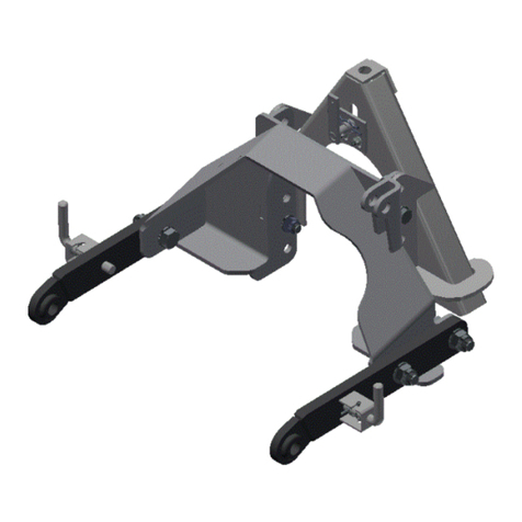
matev MOW-H/M 140 FM Installation instructions

matev GmbH
Nürnberger Str. 50
90579 Langenzenn
T +49 (0) 9101 9087 -0
F +49 (0) 9101 9087 -20
www.matev.eu
Version 06/2014
Original Operating Manual
MOW-H/M 140 FM Front Mower
MOW-H/M 160 FM Front Mower
MOW-H/M 190 FM Front Mower

Contents
Page 2
Table of contents
1About this operating manual....................................................................................3
2Safety.........................................................................................................................4
2.1 Intended use ...............................................................................................................4
2.2 Qualifications of personnel ..........................................................................................4
2.3 General safety instructions..........................................................................................4
2.4 Special safety notices .................................................................................................4
3Task and use .............................................................................................................7
3.1 Task............................................................................................................................7
3.2 Function ......................................................................................................................7
3.3 General instructions for mowing ..................................................................................7
4Mounting the implement...........................................................................................8
4.1 Mounting the front mower on the tractor vehicle..........................................................9
4.2 Mowers with mechanical drive ....................................................................................9
4.2.1 Adapting the universal joint shaft.................................................................................9
4.2.2 Mounting the universal joint shaft..............................................................................11
4.2.3 Dismounting the universal joint shaft.........................................................................12
4.3 Mowers with hydraulic drive ......................................................................................12
4.4 Mounting the suction port..........................................................................................12
5Operation.................................................................................................................14
5.1 Adjusting the cutting height .......................................................................................14
5.2 Adjusting the air intake..............................................................................................15
6Maintenance ............................................................................................................16
6.1 Maintenance after 50 operating hours or after a longer standstill period....................16
6.2 Mounting the V-belt...................................................................................................16
6.3 Sharpening the mower blades...................................................................................17
6.4 Faults........................................................................................................................18
6.5 Repair .......................................................................................................................18
7Disposal...................................................................................................................19
8Guarantee ................................................................................................................19
9Technical data .........................................................................................................19
10 List of illustrations..................................................................................................20
11 EC Declaration of Conformity ................................................................................22

About this operating manual
Page 3
1 About this operating manual
Dear customer! Dear customer!
Thank you for purchasing this implement, we appreciate your trust.
Prior to using this implement for the first time, read this operating manual carefully and
conscientiously all the way through.
Keep this operating manual where it is easily accessible. This will enable you to refer to
important information and handling instructions as needed.
Listings with bullet points are marked as follows:
Text
Text
Text . . .
Handling instructions are marked in the sequence in which they should be executed, as
follows:
1. Text
2. Text
3. Text . . .
The device is subject to change in the interest of technical progress. All
information, illustrations, and technical specifications represent the latest
status at the time this manual was published. The manufacturer reserves the
right to make changes at any time in the interest of technical progress.

Safety
Page 4
2 Safety
Guidelines and instructions with which you must comply, are summarized in this section.
2.1 Intended use
The implements are developed for municipal tractors, or carrier vehicles with the following
power ratings:
MOW-H/M 140 FM for tractors from 12 kW to 23 kW
MOW-H/M 160 FM for tractors from 17 kW to 35 kW
MOW-H/M 190 FM for tractors from 25 kW to 50 kW
Do not operate these implements on any other types of machines.
All other uses are excluded.
Non-intended use causes:
Health hazards for the operator or for third parties
Damage to the tractor and the implements
Environmental damage
2.2 Qualifications of personnel
Only authorized or instructed personnel should install, operate, and maintain the imple-
ments. The operator must have read and understood this operating manual.
2.3 General safety instructions
General safety instructions are explained in this section. These safety instructions are
used in the subsequent chapters. In addition to the safety aspect, you will save money
and work time if you follow these instructions.
Danger!
Severe injury to the operator or third parties occurs.
Comply with the safety instruction.
Attention!
Minor injury to the operator or third parties
can occur. The tractor, the grass collection device or the environment can
be damaged.
Comply with the safety instruction.
Note!
Important, helpful tips or information for the operator.
Read this note. It facilitates your work.
2.4 Special safety notices
Safety instructions are specified in this chapter that are also affixed as stickers on the im-
plements.

Safety
Page 5
Attention!
Prior to performing maintenance and repair tasks,
turn off the engine and remove the key!
Attention!
Do not position yourself in the area of the drive shaft.
Danger of injury!
(For mowers with mechanical drive)
Attention!
Injuries due to fluid escaping under high pressure.
Comply with the instruction in the operating manual.
(For mowers with hydraulic drive)
Attention!
Prior to start-up read and comply with the operating manual
and the safety instructions!
Attention!
Danger due to parts being thrown out
when the engine is running - maintain a safety
distance!
Attention!
Only touch machine parts,
after they have come to a complete standstill!
Attention!
Do not open or remove protective devices
when the engine is running.

Safety
Page 6
Attention!
During operation, maintain a sufficient distance
to the mowing blade!
Attention!
Implement is only suitable for a PTO shaft speed of 2000 rpm!
Attention!
Implement is only suitable for a PTO shaft speed of 1000 rpm!
Attention!
Implement is only suitable for a PTO shaft speed of 540 rpm!
Attention!
Implement is only suitable for clockwise PTO shaft rotation!
Attention!
Implement is only suitable for counterclockwise PTO shaft rotation!
Attention!
Do not allow the mower to run without discharge guard or suction port!
Lubricating point

Task and use
Page 7
3 Task and use
3.1 Task
The rotary mower is used for mowing green areas. The area of application extends from
manicured lawns, to matted grass to uncultivated land.
3.2 Function
The front mower works with three rotating blades and it is powered by the tractor via the
front PTO shaft or the hydraulic system. When the mower is used as a rear mower, it is
powered by the rear PTO shaft.
Use of the rotary mower with side discharge: Through the rotating blades the grass
is cutting and the cuttings are laterally accelerated out of the rotary mower. If the
mower is operated in conjunction with a suction turbine and collection container the
cuttings can be simultaneously collected. Appropriate devices are available on requ-
est.
Use as a mulcher: Through the rotating mulch blades the grass is cut and the closed
mulch insert prevents the cut grass from exiting the mower. The air supply on the
bearing brackets must be completely closed. The grass remains on the ground at the
point where it was cut. The cutting height must be selected so that a maximum of
one third of the grass height is cut. The finely cut grass must remain in the 2/3 of the
grass height that is uncut, and through rotting processes serve as a nutrient for the
soil.
3.3 General instructions for mowing
Fig. 1: Clean the work terrain
Prior to mowing, remove objects on the work terrain that could be tossed up
by the implement.
Always mow around trees and bushes counterclockwise so that the cuttings are not
thrown toward the obstruction.

Mounting the implement
Page 8
Fig. 2: Irregular area
Divide irregular areas into smaller sections.
Change the mowing pattern frequently; do not always work in the same pattern.
Fig. 3: Large area
Mow large free areas as shown on Fig. 3.
Fig. 4: Small area
If you do not use a collection container, mow small areas as shown in Fig. 4 - two to three
rounds clockwise, the rest counterclockwise. Thus you prevent the mower from getting
jammed with accumulated cuttings.
4 Mounting the implement
Switch off the tractor and remove the ignition key before mounting or dis-
mounting the implements.
Prior to mounting on the tractor, ensure that the PTO shaft rpm, and the PTO
shaft direction of rotation agree with the information on the mower.

Mounting the implement
Page 9
Enter the vehicle chassis number of the rotary mower in section 6.5 of this
operating manual.
4.1 Mounting the front mower on the tractor vehicle
Fig. 5: Mount the mower on the tractor vehicle
The following optional attachment possibilities are available for the mower:
Attachment - cat. 0
Attachment - cat. 1
Attachment - cat. 1 quick-catch hooks
Attachment - ScanFrame
1. For cat. 0, cat. 1 and ScanFrame the mower is hooked into the coupling triangle and
fastened on the coupling support with the aid of the fastening screw. For cat. 1
quick-catch hook the lower link of the front power system is positioned relative to the
mower in such a manner that when lifting out the quick-catch hooks take up the low-
er links of the attachment. Subsequently the upper link is fastened on the mower.
4.2 Mowers with mechanical drive
4.2.1 Adapting the universal joint shaft
Depending on tractor type the supplied universal joint shaft may be too
long.
Execute the steps described below to shorten the universal joint shaft.
To check whether the universal joint shaft is the correct length for your tractor you must
attach the mower to the tractor. In this regard, proceed as described in section 4.1.
Fastening screw on the
coupling support.

Mounting the implement
Page 10
When attaching and detaching particularly note: Switch off the tractor en-
gine and remove the ignition key.
Only use the supplied material.
Comply with the instructions specified in the operating manual provided by
the manufacturer of the universal joint shaft.
Mount the universal joint shaft as described in the original manual supplied
by the manufacturer of the universal joint shaft.
1. Pull the two halves of the universal joint shaft apart.
2. Mount one half of the universal joint shaft on the tractor and mount the other half on
the mower.
To do this proceed as described in section 4.2.2.
3. In the shortest operational work position, mark the piece that will be sawn off on one
half of the universal joint shaft (see Fig. 6).
Fig. 6: Mark the piece that will be sawn off
4. Dismount the marked half of the universal joint shaft.
To do this proceed as described in section 4.2.3.
5. Cut off the universal joint shaft guard to the marking (see Fig. 7).
Fig. 7: Cut off the universal joint shaft guard
6. Saw off the profile tube (see Fig. 8).

Mounting the implement
Page 11
Fig. 8: Saw off the profile tube
7. Deburr the sawn edges (see Fig. 9).
Fig. 9: Deburr the sawn edges
8. Repeat steps 4 to 7 on the other half of the universal joint shaft.
9. Grease the profile tube (see Fig. 10).
Fig. 10: Grease the profile tubes
10. Slide the profile tubes together.
4.2.2 Mounting the universal joint shaft
1. Press the locking pin on the outer fork and keep it depressed.
2. Slide the outer fork onto the profile stub of the PTO shaft on the tractor.
3. Release the locking pin.
4. Slightly move the universal joint shaft back and forth until the locking pin audibly
locks in place.
5. Repeat steps 1 to 4 to attach the universal joint shaft on the mower.
6. Hook the universal joint shaft safety chains to a stationary part on the tractor and on
the mower (see Fig. 11).

Mounting the implement
Page 12
Fig. 11: Safety chain on the universal joint shaft
4.2.3 Dismounting the universal joint shaft
1. Detach the safety chain on both sides.
2. Press the locking pin on the outer fork and keep it depressed.
3. Pull the outer fork down from the profile stub of the PTO shaft on the tractor.
4. Release the locking pin.
5. Repeat steps 2 to 4 to dismount the universal joint shaft on the CLS.
4.3 Mowers with hydraulic drive
1. Connect the 3 hydraulic hoses (flow, return, and leak oil line) to the vehicle.
2. Place the front hydraulics in float position.
3. Switch the mower on briefly.
4. Check the direction of rotation of the blades. The blades must rotate clockwise (as
viewed from above).
Never reach into the mower when the blades are turning.
Switch off the tractor and remove the ignition key before you reach into the
mower. Ensure: The mower blades continue to rotate after the engine is
switched off. Wait until the blades have come to a complete standstill before
you reach into the mower.
You can detect the direction of rotation if you observe the lubricating nipple
through the bore in the plastic housing.
5. If necessary swap out the flow and return lines.
4.4 Mounting the suction port
The suction port is only required if a grass collection device is used.

Mounting the implement
Page 13
Fig. 12: Suction port mounted
1. Hold the suction port with the hinge strip on the mower discharge.
2. Connect the suction port with the port plug on the mower.
3. Secure the support plug with the provided stop nut.
The suction port simultaneously serves as protection against rock impact.
In accordance with the Machinery Directive, the protective devices must not
be capable of being detached without tools. Do not forget to secure the port
connector with aid of the stop nut.
If you use the side discharge without suction port, you must mount the rock
impact guard on the mower, secure it with the stop nuts and flip it down. Do
not use the side discharge without rock impact guard.
Fig. 13: Rock impact guard on the side discharge
Port plug
Hinge strip
Rock impact guard
Suction port
Stop nuts

Operation
Page 14
5 Operation
Before starting up the implement, read the instructions on safety and han-
dling for operation of the entire implement and connection to the tractor.
To get a clean cutting pattern, the speed and the direction of rotation of the
PTO shaft of the tractor must agree with the information on the mower, see
chapter 2.4.
The cutting pattern depends on many factors: Drive speed, grass height,
grass density, grass type, wetness, and rpm. For a clean cutting pattern you
should drive at walking speed at full engine rpm.
Never reach into the mower when the blades are turning.
Switch off the tractor and remove the ignition key before you reach into the
mower. Ensure: The mower blades continue to rotate after the engine is
switched off. Wait until the blades have come to a complete standstill before
you reach into the mower.
When lowering the mower via the front power system, always ensure that
there are no other persons in the danger zone.
For operation with side discharge, without extraction, prior to switching on
the PTO shaft, ensure that on one is closer than 5 m to the side discharge.
5.1 Adjusting the cutting height
Attention!
Adjust the four wheels uniformly.
1. Lift out the mower with the aid of the front power system.

Operation
Page 15
Fig. 14: Caster on the rotary mower
2. Hold the caster firmly and remove the linch pin.
3. Pull the wheel downward slightly.
4. Pull out the required number of spacer rings from the lower flattened surface, and fit
them on again on top. OR
Take off the required number of spacer rings from the top and slide them on again
on the flattened point on the bottom.
5. Secure the wheel with the linch pin.
6. Repeat the instructions 2 - 5 on the other three wheels.
5.2 Adjusting the air intake
For clean grass flow it is important that sufficient air can flow into the mower. The intake
air is accelerated to through the mower discharge together with the cut grass. This is the
only to exclude the possibility of clogs in the mower or in the suction port. As a rule, air is
supplied through the gap between the ground and the mower. For extremely dense grass
and low cutting height, the gap between the turf and the mower is small. In this case little
air can flow into the mower and the grass flow worsens. In order to optimally mow with
dense grass and low cutting height, the mower has three air regulating disks. These are
arranged centrally around the blade units. When opening the air regulating disks air from
above can flow into the mower and thus ensure a better grass flow.
Fig. 15: Adjusting the air intake
1. Remove the plastic covers on the mower.
2. Unscrew the fastening nuts of the air regulating disks.
Air regulating disk
Fastening nut

Maintenance
Page 16
3. Turn the air regulating disks in such a manner that the air openings on the disk
agree with the air openings on the bearing block.
4. Tighten the fastening nuts of the air regulating disks.
5. Mount the plastic covers.
Do not operate the mower without the protective cover over the belt drive.
When mulching the air openings must be completely closed
6 Maintenance
Attention!
Before each use of the machine check all safety-relevant parts.
6.1 Maintenance after 50 operating hours or after a longer standstill period
Lubricate the following parts with the grease gun:
Casters
Blade bearing arrangement
Bearing arrangement of the belt tensioner
At regular intervals, and always at the beginning and end of the season, the moving parts
of the implement must be greased or oiled.
If there is no lubricating nipple at these points, then the area must be greased with a
brush or lubricated with oil.
Check the air pressure in the tires. The tire pressure must be 1.5 bar.
6.2 Mounting the V-belt
If you must replace the V-belt, when mounting, ensure correct mounting of the V-belt:

Maintenance
Page 17
Fig. 16: MOW-H/M 140 FM - mounting the V-belt
Fig. 17: MOW-H/M 160 FM - mounting the V-belt
Fig. 18: MOW-H/M 190 FM - mounting the V-belt
Attention!
The springs of the tension pulley are tensioned. Ensure that both ends of
the springs are hooked in correctly. The V-belt is attached by unscrewing a
belt pulley. It may be necessary to tension the springs of the tension pulley
at the same time.
6.3 Sharpening the mower blades
The special mower blades are made of hardened, yet ductile steel. These blades ensure
an optimal cut and at the same time are resistant to breakage and splintering. The blades
are wear parts and must be resharpened regularly.

Maintenance
Page 18
The fastening screw of the mower blade must be lightly oiled and tightened with a torque
wrench as specified below:
MOW-H/M 140 FM - 115 Nm
MOW-H/M 160 FM –250 Nm
MOW-H/M 190 FM –250 Nm.
Attention!
Wear suitable protective equipment for attachment and removal, or when
sharpening the blades: Protective work gloves, protective goggles.
If a blade becomes deformed, e.g. through striking larger rock or piece of iron, then the
blade must be replaced.
6.4 Faults
Fault
Possible cause / correction
Suction port blocked
Driving too fast for the given conditions /
select an appropriate working speed
Mower does not start up
Heavy clogging in the mower / switch off the machine
immediately, remove the ignition key and clean the
mower
Poor cutting pattern
Driving too fast for the given conditions /
select an appropriate working speed
Blade dull / sharpen blade
Insufficient rpm / drive at full throttle
Insufficient blade speed / check whether the PTO shaft
of the tractor agrees with the rpm and the direction of
rotation specification on the mower
For dense grass and low cutting height insufficient air
supply / adjust air regulating disks, see 5.2
6.5 Repair
If there are faults, problems, or other indications of malfunction,
contact your sales consultant or contact the manufacturer directly:
matev GmbH
Nürnberger Str. 50
90579 Langenzenn
Tel.: +49 (0) 9101 9087 -0
Enter the article number and the chassis number here.
This information is on the type plate of the implement.
Article number: ........................................................................
Chassis number: .....................................................................

Disposal
Page 19
7 Disposal
The implements must be disposed of in accordance with the applicable regulations of the
municipality or the country.
Take the parts to the collection points for residual waste, special waste, or recycle them
depending on material.
Matev GmbH does not provide any disposal services.
8 Guarantee
The General Terms & Conditions of matev GmbH provide information on the guarantee
conditions.
matev GmbH
Nürnberger Str. 50
90579 Langenzenn
9 Technical data
Dimensions
MOW-H/M 140 FM
MOW-H/M 160 FM
MOW-H/M 190 FM
Width (overall)
1,668 mm
1,865 mm
2,164 mm
Height (overall)
535 mm
535 mm
535 mm
Depth (overall)
1,343 mm
1,452 mm
1,564 mm
Cutting width
1,370 mm
1,570 mm
1,870 mm
Number of blades
3
3
3
Drive type
Hydraulic or me-
chanical
Hydraulic or me-
chanical
Hydraulic or me-
chanical
Weight without accessories
162 kg
206 kg
236 kg
Safety test executed in accordance with EN 836:1997
Thrown object test
*
*
*
Strength test
*
*
*
Impact test
*
*
*

List of illustrations
Page 20
10 List of illustrations
Fig. 1: Clean the work terrain ........................................................................................................................7
Fig. 2: Irregular area ......................................................................................................................................8
Fig. 3: Large area ..........................................................................................................................................8
Fig. 4: Small area...........................................................................................................................................8
Fig. 5: Mount the mower on the tractor vehicle .............................................................................................9
Fig. 6: Mark the piece that will be sawn off................................................................................................. 10
Fig. 7: Cut off the universal joint shaft guard .............................................................................................. 10
Fig. 8: Saw off the profile tube .................................................................................................................... 11
Fig. 9: Deburr the sawn edges ................................................................................................................... 11
Fig. 10: Grease the profile tubes ................................................................................................................ 11
Fig. 11: Safety chain on the universal joint shaft ........................................................................................ 12
Fig. 12: Suction port mounted .................................................................................................................... 13
Fig. 13: Rock impact guard on the side discharge ..................................................................................... 13
Fig. 14: Caster on the rotary mower ........................................................................................................... 15
Fig. 15: Adjusting the air intake .................................................................................................................. 15
Fig. 16: MOW-H/M 140 FM - mounting the V-belt...................................................................................... 17
Fig. 17: MOW-H/M 160 FM - mounting the V-belt...................................................................................... 17
Fig. 18: MOW-H/M 190 FM - mounting the V-belt...................................................................................... 17
This manual suits for next models
2
Table of contents
Other matev Lawn Mower manuals
Popular Lawn Mower manuals by other brands

California Trimmer
California Trimmer Mower Maintenance manual

Husqvarna
Husqvarna 917.375350 owner's manual

American Lawn Mower Co.
American Lawn Mower Co. 1815-18 owner's manual

Troy-Bilt
Troy-Bilt 13AP91KT563 Operator's manual

Worx
Worx Landroid owner's manual

Poulan Pro
Poulan Pro 96042007000 Operator's manual