manuals.online logo
Brands
  1. Home
  2. •
  3. Brands
  4. •
  5. Matsushima
  6. •
  7. Switch
  8. •
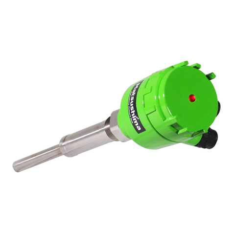
  9. Matsushima MWFS-SW-02C User manual

Matsushima MWFS-SW-02C User manual

MMWFS-002E
Rev3:May.28,2014
Contents
Safety Precautions・・・・・・・・・・・・・・1
1.Outline ・・・・・・・・・・・・・・・・・・・2
2.Specifications ・・・・・・・・・・・・・・・・2
3.Name of each part ・・・・・・・・・・・・・・3
4.Environment in erection location (Condition)・・・5
5.Example of installation ・・・・・・・・・・・・5
6.Wiring・・・・・・・・・・・・・・・・・・・・6
7.Adjustment ・・・・・・・・・・・・・・・・・7
8.Maintenance・・・・・・・・・・・・・・・・・7
INSTRUCTION MANUAL
FOR
MICROWAVE FLOW SWITCH
TYPE
MWFS-SW-02C
※An operator should read carefully this instruction manual and conduct
correct handing.
1-8-18Norimatsu-Higashi,Yahatanishi-ku,Kitakyushu807-0837Japan
PhoneNo.(8193)691-3731FaxNo.(8193)691-3735
http://www.matsushima-m-tech.com
E-mailsales@matsushima-m-tech.com
− −1
Safety Precautions
Be sure to thoroughly read the instruction manual before using the products.
Keep the instruction manual in a safe, convenient location for future reference.
All or part of the contents described in this manual may be changed without any notice.
Due to our constant striving for further improvement of products, parts or products that differ from those
described in this manual may be substituted.
WARNING (Failure to observe this WARNING may cause a fatal or serious injury.)
・Be sure to confirm that any peripheral equipment does not move before installation work.
In addition, observe safety requirements for installation work where high-place work is expected.
・Be sure to turn off the power source before wiring, mounting and transportation work. (Failure to
observe this WARNING may result in an electric shock/ injury or equipment damage due to short-circuit.)
・Carry out wiring work correctly with reference to a proper drawing.
・Never disassemble the equipment. (Failure to observe this WARNING may result in an electric shock.)
・Do not open the cover under an explosive environmental condition when power is entered.
(Failure to observe this WARNING may result in an injury or equipment damage.)
・Do not place or store the equipment in any hostile environmental place where it will be subjected to
direct sunlight, rain, water droplet, hazardous gas/water, etc..
CAUTION (Failure to observe this CAUTION may cause a moderate injury or equipment damage.)
・Do not use the equipment for any purpose other than the original purpose of use.
・Be sure to confirm the specification of equipment and use the equipment within the range of specification.
(Mounting conditions such as temperature, power source, frequency, etc.)
・Make sure a correct wiring before applying power source.
・Do not have a shock or strong impact to the equipment.
(Failure to observe this CAUTION may result in equipment damage.)
・Be sure to connect necessary terminals (grounding, etc.).
・Remove all wiring to the equipment before doing electrical welding work near the equipment.
・Do not forcedly bend or pull the lead wire also do not use unnecessarily long wire.
・Tighten the cover, lead outlet, etc. properly so that dust, rainwater, etc. do not enter inside the equipment.
・Do not use the equipment under a corrosive condition (NH3, SO2, CI2, etc.).
・Be sure to tighten the cable grand so that outer air does not enter inside the equipment.
・When applying piping connection such as conduit, etc. instead of cable grand, apply putty or
equivalents on the cable entry so that outer air does not enter inside the equipment.
IMPORTANT (indicates notes or information to help customers.)
Limitations of Warranty:
・Warranty period shall be one year from the date of delivery (ex-factory).
・Any damage of any other products that have occurred for use of the equipment is not covered by
this warranty. Also any loss induced by failure or malfunction of the equipment is not covered by
this warranty.
・Failure or malfunction caused by following are not covered by this warranty:
a. Modification or repair by a party other than MATSUSHIMA’s authorized personnel,
or replacement of parts not recommended by MATSUSHIMA.
b. Inadequate storage, installation, use, inspection or maintenance that does not comply
with specifications.
c. Cause for any peripheral equipment or device.
d. Accident beyond control and force majeure (fire, earthquake, flood, riots, etc.).
Lack of instructions to MATSUSHIMA for information or safety requirements that can be predicted only
by customers’ side.
This warranty conditions do not limit customers’ legal right.
Price for the equipment does not include any charge for services such as commissioning,
supervising, etc..
!
!
!
− −2
1.Outline
This Flow Switch is used to detect whether the solid material is flowing or not by utilizing
the high-level penetration ability of microwave and the Doppler effect.
When the microwave from the Flow Switch is reflected off the flowing solid material,
the frequency of the transmitted wave and that of the reflected wave differ according to
the Doppler effect.
If the solid material is not flowing, there is no frequency difference.
To detect whether the solid material is flowing or not, the Flow Switch judges whether there is
a frequency difference or not.
Also the microwave is not affected by any foreign matter adhering to the transmitter face of
the Flow Switch, vapor, floating dust due to the strong penetration ability.
Therefore the Flow Switch can detect the flow through the insulated pipe.
2.Specification
2- 1. Type MWFS-SW-02C
2- 2. Power supply AC 90〜230V 50/60Hz(Max. 5.5W)
2- 3. Operating distance 2m(The operating distance shall change
according to the grain size, speed, reflectance.)
2- 4. Frequency Approx. 24GHz
2- 5. Sending output 7mW typ.
2- 6. Control output It outputs it with the solid flows.
1-SPDT (AC 250V 3A)
【Operation】
Detection : It turns it on while flowing.
ON DELAY : It turns it on with it flows more than set time.
OFF DELAY : It turns it off with it doesn't flow more than
2- 7. Self-diagnosis output Do the self-diagnosis of the transmission decrease and
the power failure of the micro wave and it outputs it.
1-SPDT (AC 250V 3A)
【Operation】
When it is normal : ON (COM-NC)
Abnormal circumstances: Decrease and about six seconds of
transmitting power or, after it
blacks out, it turns it off.
2- 8. Integration 0.1 〜10s (It is possible to adjust it. ON/OFF DELAY)
2- 9. Permissible temperature -10 〜+55℃(Ambient temperature)
2-10. Permissible pressure −980kPa 〜 +980kPa
2-11. Material Housing :ADC
Boss :SUS304
Sending side:PTFE
2-12. Installation method G1 (Attachment : Lock nut , Packing)
2-13. Enclosure IP65
2-14. Coating color Munsell 7.5GY6/10
2-15. Weight Approx. 2.0kg
− −3
3.Name of each part
Figure 1 Panel detailed chart
Table 1.Name and substance
No. Name Substance
1COARSE Volume
It is a volume for the adjustment to match it to the
measurement environment.
Volume to adjust rough of receiving wave. (0:Fine〜10:Coarse)
2FINE Volume
It is a volume for the adjustment to match it to the
measurement environment.
Volume to adjust sensitivity of receiving wave.(0:Low〜10:High)
3ON DELAY Volume
Set the time of ON DELAY in the range of 0.1 and 10s.
The Flow Switch doesn’t output for the set time even when the material is
flowing and the detection is being made.
4OFF DELAY Volume
Set the time of OFF DELAY in the range of 0.1 to 10 sec.
The Flow Switch keeps the output detected before the material stops
flowing for the set time.
5POWER Lamp (Green) Lights up when power-supply voltage is applied.
6FAULT Lamp (Red) When transmitting power decreases or sending and the reception module
break down, it lights.
7FLOW Lamp (Yellow)
Lights up when the Flow Switch detects the flow of the object.
Continuously lighted while the object is flowing, and turned off
when the flow stops.
8Lead outlet Cable seize : 7〜13mm
9Terminal Figure 2. shows the terminal array.
Figure 1 Panel
(The lead drawing out mouth was seen forward)
COARSE Volume
ON DELAY
Volume
OFF DELAY
Volume
FLOW Lamp
(Yellow)
FAULT Lamp
(Red)
Terminal ※Volume increases by
turning clockwise.
FINE
Volume
POWER Lamp
(Green)
− −4
FLOW Side FAULT Side
Power OFF
Power ON
No flow
Power ON
Flow
Power ON
Fault
Figure 2. Terminal array
Power supply
AC90〜230V 50/60Hz
Figure 3. Functionchart
Flow detection
(No flow)
Failure alert
(When it is normal)
AC
L
AC
NCOM NO NC COM NO NC
POWER FLOW FAULT
CO
NO
NC
CO
NO
NC
CO
NO
NC
CO
NO
NC
CO
NO
NC
CO
NO
NC
CO
NO
NC
CO
NO
NC
− −5
4.Environment in erection location (Condition)
4-1. Temperature -10℃〜+55℃
(It is not possible to use it in the place with the fear of freezing.)
4-2. Humidity 90%or less
(Transmitting part and receiving part is non condensing)
4-3. Pressure -980kPa〜+980kPa(-10〜+10kgf/cm2)
4-4. Vibration If resonance occurs because of the vibration resulting from the
application structure, the flow switch may malfunction.
Be sure to install the flow switch in a location free from vibration.
5.Example of installation
Figure 4 and 5 show the details of a typical installation.
Mount the flow switch with G1 screws.
The mounting part and the main body can be separated.
Use a sealant such as liquid gasket to fill the gap between the screw and the packing.
Use the accessory lock nut to install the flow switch on the pipe.
Flow switch
Packing
Lock nut
Fill the gap between the screw
and the packing with liquid
gasket.
Then attach the flow switch.
Pipe wall
Fig
ure
5
.
Details
of installation
Figure 4. Example of installation
Lead outlet
Pipe wall
Housing case
Housing cover
G1
Please tighten the M5-Bolt and Nut
when you install it.
− −6
Installation that considers adhesion and piling up
Please install it referring to Figure 6.
Please install the cover board of teflon with a low
permittivity or a material ceramic etc. when this installation
is difficult and give to me as an installation that penetrates
the micro wave.
Important:The cover board of physical
properties of electroconductive
cannot be used.
Especially, when the measurement
thing that contains moisture
adheres, it becomes a false detection.
6.Wiring
・Use cables of Max. 1.5mm2in diameter that are suitable for the operational environment when wiring.
(Size of recommended cable:1.25sq)
Important:The diameter of the cable for the lead out connector of the terminal box
should be between 7 mm to 13 mm.
Caution :Please execute it in the state of power supply OFF when you connect wires.
There is a possibility that the electric shock, the leak, and the ignition,
etc. happen.
Important:The state of the point of contact in Figure 7 is in the state of "Power ON ,
NoFlow".
Power supply OFF or undetection : It becomes excitation between COM-NC.
!
Figure 6. Example of installation
!
!
!
Figure 7. Terminal
− −7
7.Adjustment
Important:・When the flow intermittently becomes interrupted.
Please adjust 'ON DELAY' and the 'OFF DELAY' volume to the optimum value.
(ON/OFF DELAY setting range: 0.1-10s)
『ON DELAY』:
The Flow Switch doesn’t output for the set time even when the material
is flowing and the detection is being made.
『OFF DELAY』:The Flow Switch keeps the output detected before the material stops
flowing for the set time.
7-1. Please turn on the power supply after confirming wiring after installing Flow Switch.
The POWER lamp (green) lights when the power supply is turned on.
7-2. Turn the ON-DELAY and OFF-DELAY volumes counterclockwise at each minimum value.
(Volume : Counterclockwise)
7-3. Turn the COARSE and the FINE volumes clockwise at each maximum value.
(Volume : Clockwise)
7-4. Check the operation point of the Flow Switch at the ambient noise level.
Confirm that the FLOW lamp (left, Yellow) lights when no material is flowing.
Slowly turn the Fine volume counterclockwise and verify where the FLOW lamp turns off.
At this time, if the FLOW lamp does not turn off even when the FINE volume is turned to the middle
position, stop at the middle and turn the COARSE volume counterclockwise until the FLOW lamp
turns off.
7-5. Check the operation point of the flow switch at the signal level.
The FLOW lamp lights up when the specified amount of material flows at the specified speed.
Slowly turn again the COARSE volume counterclockwise while the material is flowing and verify
where the FLOW lamp turns off.
7-6. Set the COARSE volume to the middle between the flow switch’s operation point at the ambient
noise level confirmed in 7.4 and that at the signal level confirmed in 7.5.
7-7. If the flow is intermittent, use the ON-DELAY volume to set the no-detection and use the
OFF-DELAY volume to set the continuous-detection time.
8.Maintenance
Maintenance is not needed for the Flow Switch. Confirm the following items in periodical inspections.
8-1.Tightness of the bolts for the housing cover.
If these bolts are loose, rainwater or dust can enter from the space between the housing cover and
the case, resulting in a malfunction or failure.
8-2.tness of the lock nuts.
If these lock nuts are loose, the application facility may be affected.
8-3.Cleanliness of the transmitting face.
As aforementioned, microwaves have excellent penetration ability.
But on excessive amount of adhered matter may affect normal operations.
So the face must be periodically cleaned.
Note: Please note that the specifications or appearance may be changed without notice due to
modification of the Flow Switch.
Note: Matsushima does not take responsibility for any changes or modifications of the Flow Switch
made by the user or unauthorized personnel.
!

Other Matsushima Switch manuals

Matsushima MVL-110 User manual

Matsushima

Matsushima MVL-110 User manual

Matsushima PFM-DWS10 User manual

Matsushima

Matsushima PFM-DWS10 User manual

Popular Switch manuals by other brands

Indu-Sol PROmesh P9+ Quick start user guide

Indu-Sol

Indu-Sol PROmesh P9+ Quick start user guide

L&J TECHNOLOGIES DELAVAN MICROWAVE 320 Series manual

L&J TECHNOLOGIES

L&J TECHNOLOGIES DELAVAN MICROWAVE 320 Series manual

Sybility Easy SP-Switch quick start guide

Sybility

Sybility Easy SP-Switch quick start guide

3Com CoreBuilder 6000 supplementary guide

3Com

3Com CoreBuilder 6000 supplementary guide

Novus NVS-3104SP user manual

Novus

Novus NVS-3104SP user manual

Emerson Avocent SV 220 Quick installation guide

Emerson

Emerson Avocent SV 220 Quick installation guide

Dell EMC PowerSwitch S4810-ON installation guide

Dell EMC

Dell EMC PowerSwitch S4810-ON installation guide

LevelOne IES-0842 user manual

LevelOne

LevelOne IES-0842 user manual

ATEN CL5708IM user manual

ATEN

ATEN CL5708IM user manual

Lewmar 68001027 Instruction

Lewmar

Lewmar 68001027 Instruction

EtherWAN EX75900 Series installation guide

EtherWAN

EtherWAN EX75900 Series installation guide

Kramer 6241HDx1 user manual

Kramer

Kramer 6241HDx1 user manual

SMC Networks 8150L2 installation guide

SMC Networks

SMC Networks 8150L2 installation guide

ANTAIRA LMX-2828G-10G-SFP Hardware manual

ANTAIRA

ANTAIRA LMX-2828G-10G-SFP Hardware manual

Cisco MDS 9396S Hardware installation guide

Cisco

Cisco MDS 9396S Hardware installation guide

IN-COMMAND NCSTS9 Installation and operation manual

IN-COMMAND

IN-COMMAND NCSTS9 Installation and operation manual

Tekvox MV41 Plus user manual

Tekvox

Tekvox MV41 Plus user manual

Belkin F1DG102W - Flip Wireless KVM installation instructions

Belkin

Belkin F1DG102W - Flip Wireless KVM installation instructions

manuals.online logo
manuals.online logoBrands
  • About & Mission
  • Contact us
  • Privacy Policy
  • Terms and Conditions

Copyright 2025 Manuals.Online. All Rights Reserved.