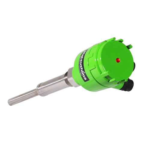
Matsushima PFM-DWS10 User manual

TDSW-001E
Rev1:2013.02.28
Contents
Safety Precautions 1
1. Introduction 2
2. Specification 2
3. Dimension Drawing 3
4. Installation 4
5. Wiring 6
6. Operation 7
7. Troubleshooting 9
INSTRUCTIONMANUAL
FOR
DUSTSWITCH
Model:PFM-DWS10
※An operator should read carefully this instruction manual and
conduct correct handing.
1-8-18Norimatsu-Higashi,Yahatanishi-ku,Kitakyushu807-0837Japan
PhoneNo.(8193)691-3731FaxNo.(8193)691-3735
http://www.matsushima-m-tech.com
E-mailsales@matsushima-m-tech.com

-
1
-
Safety Precautions
Be sure to thoroughly read the instruction manual before using the products.
Keep the instruction manual in a safe, convenient location for future reference.
All or part of the contents described in this manual may be changed without any notice.
Due to our constant striving for further improvement of products, parts or products that differ from those
described in this manual may be substituted.
WARNING (Failure to observe this WARNING may cause a fatal or serious injury.)
Be sure to confirm that any peripheral equipment does not move before installation work.
In addition, observe safety requirements for installation work where high-place work is expected.
Be sure to turn off the power source before wiring, mounting and transportation work. (Failure to observe
this WARNING may result in an electric shock/ injury or equipment damage due to short-circuit.)
Carry out wiring work correctly with reference to a proper drawing.
Never disassemble the equipment. (Failure to observe this WARNING may result in an electric shock.)
Do not open the cover under an explosive environmental condition when power is entered. (Failure to
observe this WARNING may result in an injury or equipment damage.)
Do not place or store the equipment in any hostile environmental place where it will be subjected to direct
sunlight, rain, water droplet, hazardous gas/water, etc..
CAUTION (Failure to observe this CAUTION may cause a moderate injury or equipment damage.)
Do not use the equipment for any purpose other than the original purpose of use.
Be sure to confirm the specification of equipment and use the equipment within the range of specification.
(Mounting conditions such as temperature, power source, frequency, etc.)
Make sure a correct wiring before applying power source.
Do not have a shock or strong impact to the equipment.
(Failure to observe this CAUTION may result in equipment damage.)
Be sure to connect necessary terminals (grounding, etc.).
Remove all wiring to the equipment before doing electrical welding work near the equipment.
Do not forcedly bend or pull the lead wire also do not use unnecessarily long wire.
Tighten the cover, lead outlet, etc. properly so that dust, rainwater, etc. do not enter inside the equipment.
Do not use the equipment under a corrosive condition (NH3, SO2, CI2, etc.).
Be sure to tighten the cable grand so that outer air does not enter inside the equipment.
When applying piping connection such as conduit, etc. instead of cable grand, apply putty or equivalents
on the cable entry so that outer air does not enter inside the equipment.
IMPORTANT (indicates notes or information to help customers.)
Limitations of Warranty:
Warranty period shall be one year from the date of delivery (ex-factory).
Any damage of any other products that have occurred for use of the equipment is not covered by
this warranty. Also any loss induced by failure or malfunction of the equipment is not covered by
this warranty.
Failure or malfunction caused by following are not covered by this warranty:
a. Modification or repair by a party other than MATSUSHIMA’s authorized personnel,
or replacement of parts not recommended by MATSUSHIMA.
b. Inadequate storage, installation, use, inspection or maintenance that does not comply
with Specification.
c. Cause for any peripheral equipment or device.
d. Accident beyond control and force majeure (fire, earthquake, flood, riots, etc.).
Lack of instructions to MATSUSHIMA for information or safety requirements that can be predicted only
by customers’ side.
This warranty conditions do not limit customers’ legal right.
Price for the equipment does not include any charge for services such as commissioning,
supervising, etc..
!
!
!

-
2
-
1. Introduction
This dust switch can be installed on small or medium-sized dust collectors and detects dust discharged
from the dust collector. Dust particles coming in contact with or passing near the electrode of the switch
cause an electric charge to transfer from the dust particles to the electrode.
The dust switch detects this transfer of electric charge and outputs ON/OFF signals.
2. Specification
Table 1 Specification
1. Type PFM-DSW10
2. Structure Sensor with integrated transducer
3. Equipment Specification
1) Power supply 24 VDC ±10%
2) Power consumption 2 W
Power indicator Green (Power is ON when it is lit)
3) LED indicators
Detection level
indicator Red (Dust has been detected when it is lit)
4) Signal output Open collector
output 1 output (NPN)
5) Capacity Load voltage: 5 to 30 VDC, load current: 50 mA max.
6) Lead outlet G 1/2 (Applicable cable size: 8 to 12 mm in dia.)
7) Protection IP54 (The cover is tightly closed, the lead runs through the
lead outlet, and the outlet is tightly closed.)
Probe 50 mm (Not including the Isolation)
8) Dimensions
Isolation 50 mm
Probe SUS 304
Isolation Polyacetal (POM)
9) Material
Housing Aluminum casting
10) Temperature 0 to +55 °C
11) Humidity 90% max. (No condensation)
12) Mounting G 1/2 screw
13) Mass Approx. 0.5 kg
14) Coating Munsell 7.5GY 6/10

-
3
-
3. Dimension Drawing
Fig. 1 External Dimensions

-
4
-
4. Installation
The dust switch must be installed horizontally or vertically.
・A: The Isolation must protrude at least 10 mm from the side wall of the duct.
・B: The distance between the probe tip and the side wall of the duct must be at least 10 mm.
Fig. 2 Installation 1
The dust switch might malfunction if not installed under appropriate operating conditions. Do not install
the dust switch under the following conditions or in an environment.
・Close to a very narrow section.
・A nonconductive pipe, short pipe, or duct is used.
・Environment and conditions do not comply with the Specification.
・There is a chance that dust may accumulate between the pipe wall and the probe when the base
pipe is extended with a short pipe.
・The space between the probe tip and the side wall is less than 10 mm.
Fig. 3 Installation 2

-
5
-
●Installation example to Dust Collector
Prepare a duct for installing Dust Switch to the Exhaust port of Dust Collector.
If Dust Switch is installed to this duct, it is possible to deduct the filter breakage of
Dust Collector in the early stage.
第4図.集塵機への取付図
Air suction port
Exhaustairduct
Exhaust
port

-
6
-
5. Wiring
5-1. Wiring Connections
Before wiring, be sure to confirm that the power supply has been turned off.
Failure to observe this instruction may result in an electric shock, electric leakage, fire or other such
accident.
Use shielded pair cable: 0.32 mm to 0.65 mm in diameter x 2.
The cable length should be no more than 100 m taking into consideration the voltage drop.
Power supply: 24 VDC ±10%
Open collector output
The wiring method for the output of the open collector differs in accordance with the power supply
used and the output method of the signal. Use the connection method best suited for the
application.
Fig. 4 Schematic Diagram
5-2 Earth connection
The earth terminal is located on the side of the housing.
Be sure to earth the dust switch through the earth terminal.
If not, noise might cause the dust switch to malfunction.
Fig. 5 Earth Terminal
Caution
:
The earth line should not be removed even at the maintenance in case it may cause a fault.
!

-
7
-
6. Operation
6-1. Parts Arrangement
The names and layout of the parts on the board are as shown in the figure below.
①
②
③
④
⑤
⑥
Fig. 6 Parts Arrangement on the Board
Table 2 Parts Names
*The volumes for adjustment can be turned either clockwise (toward 10) or counterclockwise (toward 0).
No. Name Description
①Terminal block Power input, open collector output
②Power indicator (green) Lights up when the power is turned ON.
③Detection level indicator (red) Lights up when dust is detected.
④Detection level adjusting volume Do not change the factory setting.
⑤Detection level delay setting volume Operating time: 0 (0 sec.) to 10 (10 sec.)
⑥Sensitivity adjusting volume Sensitivity level: 0 (lowest sensitivity) to 10 (highest sensitivity)

-
8
-
6-2. Adjustment
1) Sensitivity adjusting volume
The sensitivity adjusting volume is used to adjust the detection sensitivity according to the
environment.
The setting range is 0 to 10. The detection sensitivity decreases as the volume is turned
counterclockwise toward 0, and increases as turned clockwise toward 10.
<<Adjustment>>
・Operate the facility after installing Dust Switch.
・Turn Sensitivity adjusting volume clockwise to the position where Detection
Level Indicator(red) lights up.
・After Detection Level Indicator lights up, turn Sensitivity adjusting volume
counterclockwise little by little to the position Detection Level Indicator goes out.
・Turn it further counterclockwise one or two more scales from the position Detection
Level Indicator goes out in order to prevent chattering.
●When a small amount of dust leakage is required:
Turn Sensitivity adjusting volume clockwise for higher sensitivity to detect a small amount of
dust.
●When a small amount of dust leakage needs not to be detected:
Turn Sensitivity adjusting volume counterclockwise for lower sensitivity and the small amount
of dust leakage will not be detected.
2) Detection level delay setting volume
Detection delay setting is a setting to delay the output of detection alarm (called “delay function”).
This delay function can alleviate the effect of chattering if chattering occurs in the signal under
detection. The delay can be adjusted at roughly one-second increments/decrements between
0 and 10 seconds.
[ Delay Operation Example ]
Fig. 7 Detection Level Delay Operation Chart
Detection level delay set value
Time[s]
No delay setting
Delay setting

-
9
-
7. Troubleshooting
If the problem cannot be solved by taking the applicable actions, please contact Matsushima Machinery
Laboratory.
Table 3 Troubleshooting
Problem Probable cause Items to be checked
・Power indicator
does not light
up.
1) Power is not supplied.
2) Power supply Specification differ from what
was confirmed at the delivery.
1) Check wiring connections.
2) Check if the voltage of the power
supply is correct.
・Detection level
indicator does
not light up.
1) Sensitivity adjusting volume is set to the
lowest (0).
2) Material is adhering to the probe.
3) The dust switch is not earthed or is not
earthed correctly.
4) Failure of the device
1) Check by turning the volume to
change the level of sensitivity.
2) Check for any material adhering to
the probe section.
3) Check whether the dust switch is
earthed through the earth terminal
on the side of the housing.
4) Contact Matsushima Machinery
Laboratory.
・Detection level
indicator does
not go out.
1) Sensitivity adjusting volume is set to the
highest (10).
2) Material is adhering to the probe.
3) The dust switch is not earthed or is not
earthed correctly.
4) Failure of the device
5) A large amount of material is flowing.
1) Check by turning the volume to
change the level of sensitivity.
2) Check for any material adhering to
the probe.
3) Check whether the dust switch is
earthed through the earth terminal
on the side of the housing.
4) Contact Matsushima Machinery
Laboratory.
* Specification, design, etc. are subject to
Table of contents
Other Matsushima Switch manuals