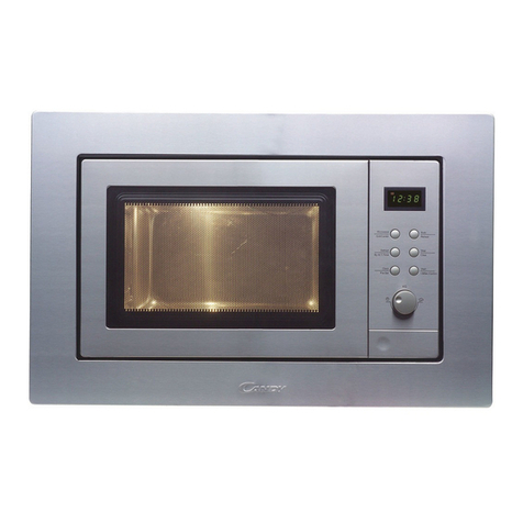
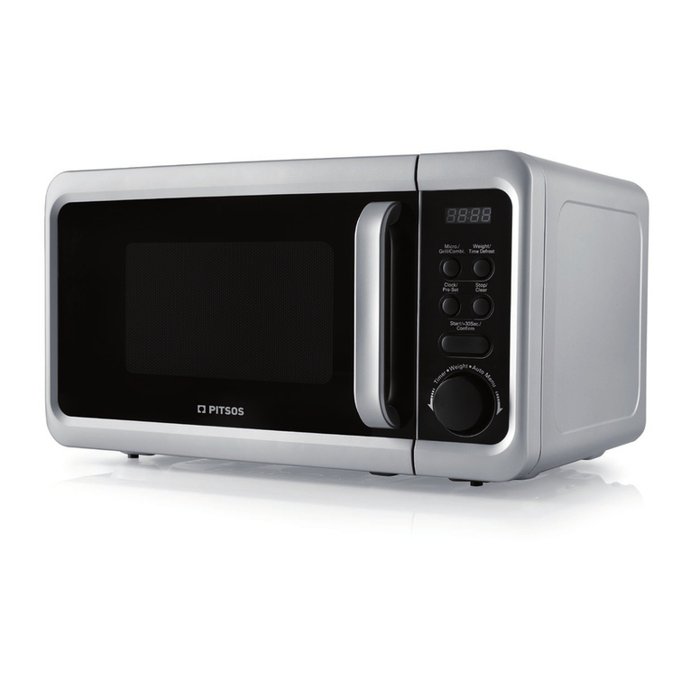
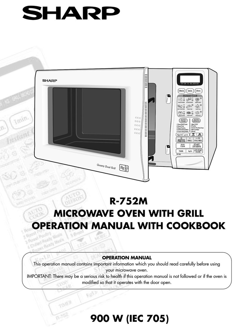
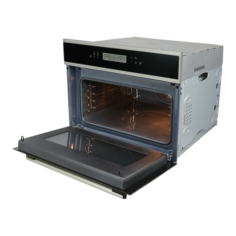
Matsushita Electric NN-V688W User manual

ORDERNO. MOD9812220C3
Microwave Oven
NN-V688W / NN-V688WS / NN-V698J / NN-V698JS / NN-
V668W / NN-V668WS
SPECIFICATIONS
1998 Matsushita ElectricIndustrial Co., Ltd. All rights reserved.
1

Unauthorized copying and distribution isaviolation of law.
1. CONTROL PANEL
2

2. OPERATION AND DIGITAL PROGRAMMER
CIRCUIT TEST PROCEDURE
3

4

3. SCHEMATIC DIAGRAM (KNQ, MNQ, SNM, YNQ)
5

4. SCHEMATIC DIAGRAM (HNE, LNK, TNE)
6

5. SCHEMATIC DIAGRAM (XNE)
7

6. SCHEMATIC DIAGRAM (WNT)
8

7. DESCRIPTION OF OPERATING SEQUENCE
7.1. Variablepower cooking control
HIGH VOLTAGE INVERTER POWER SUPPLY (U) controls output powerbythe signal from
Digital ProgrammerCircuit (DPC). Powerrelay1 stays on but the inverterdrive signal tocontrol
it's output power.
NOTE 1: The ON/OFF time ratiodoes not correspond withthe percentage of microwave power
since approximately2 seconds are requiredforheating of magnetron filament.
NOTE 2: If microwave cooking is over8 minutes withHIGH power, fanmotorrotates for1
minute aftercooking tocool ovenand electric components.
9

7.2. Grill cooking
The digital programmercircuit generates the powerrelay4 control signal at ON time during grill
cooking.
7.3. Combination cooking
Combination cooking is accomplishedbymicrowave and grill cooking. The digital programmer
circuit controls ON-OFF time of powerrelay1 and 4 as showninthe table.
NOTE: Aftergrill and combination cooking, fanmotorrotates for1 minute tocool ovenand
electric components.
7.4. Auto Defrost, One Touch Menu and Auto Reheat Control
Whenthose autocontrol feature is selectedand Start padis pressed:
1. The digital programmer circuitdetermines the power level and
cooking time to complete cooking and indicates the operating
state inthe display. The tableshowsthe corresponding cooking
times for respective weight bycategories.
2. When cooking time inthe displaywindow has elapsed, the oven
turns off automaticallybythe controlled signal from the digital
programmer circuit.
NOTE: Afterone touchmenu and autoreheat cooking, fanmotorrotates for1 minute tocool
ovenand electric components.
10

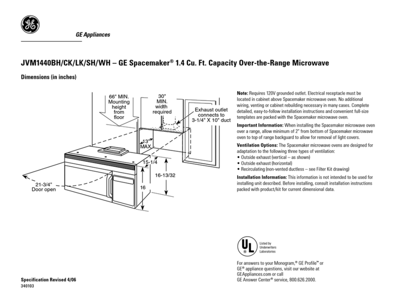
7.5. One touch cooking (Auto sensor cooking)
Autosensorcooking is a revolutionarywaytocook bymicrowave without setting a powerlevel
orselecting a time.
All that is necessaryis toselect anAutoSensorProgrambefore starting tocook.
Understanding AutoSensorCooking
As a food cooks, a certainamount of steamis produced. If the food is covered, this steam
builds up and eventuallyescapes fromthe container. InAutoSensorCooking, a carefully
designedinstrument, calledthe steamsensorelement, senses this escape of steam. Then,
basedupon the AutoSensorProgramselected, the unit will automaticallydetermine the correct
powerlevel and the properlengthof time it will take tocook the food.
NOTE: AutoSensorCooking is successful withthe foods and recipes found inthe AutoSensor
Cooking Guide. Because of the vast differences infood composition, items not mentionedinthe
Cooking Guide shouldbe preparedinthe microwave ovenusing powerselect and time features.
Please consult Variable PowerMicrowave Cookbook forprocedures.
Explanation of the AutoSensorCooking process
1. During the first 10 second period there isno microwave activity,
and when calculating the T2 time byusing the formulabelow
11

make sure this10 seconds issubtracted from the T1 time. Inother
words T1 time starts at the end of the 10 second period.
2. T1 time The total amount of time ittakes the microwave oven to
switch to T2 time after the 10 second period.
3. T2 time When the steam escapes from the cooking container
placed inthe oven, the steam sensor detects itand the
microprocessor calculates the balance of cooking time. ThisT2
time isthen showninthe displayand begins counting down.
Balance of cooking time (T2 time)
The balance of cooking time whichis calledT2 time, canbe calculatedbythe following formula.
T2 time (insec.) = T1 time X K factor
NOTE: Remember, the T1 time starts afterthe 10 second period. The coefficient K is
programmedIntothe microprocessormemoryand theyare listedinthe following tables along
withthe P1 and P2 powers.
NOTE: When"More" or"Less" padis selected, the K factorvaries resulting inT2 time tobe
increasedordecreased.
Example of calculating the T2 time
Example 1: If the T1 time is measuredtobe 2 minutes and 40 seconds afterthe 10 second
period, and the Autoprogramselectedis Vegetables:
T2 = T1 X K
= 2 min. and 40 sec. X 0.1
= 160sec. X 0.1
= 16 sec.
7.6. Auto Sensor Reheat
AutoSensorReheat is a quick and easywaytoreheat refrigeratorand roomtemperature foods.
Simplypress the reheat pad. There is no needtoselect powerlevel and cooking time.
NOTE: The AutoSensorReheat process is same as AutoSensorCooking process.
12

8. CAUTIONS TO BE OBSERVED WHEN
TROUBLESHOOTING
Unlike manyotherappliances, the microwave ovenis high-voltage, high-current equipment.
Though it is free fromdangerinordinaryuse, extreme care shouldbe takenduring repair.
8.1. Check the grounding
Donot operate on a 2-wire extension cord. The microwave ovenis designedtobe usedwhen
grounded. It is imperative, therefore, tomake sure it is groundedproperlybefore beginning
repairwork.
8.2. Inverter Warnings (NEW H.V.)
13

14

15

8.3. When parts must be replaced, remove the power plug from the
outlet.
8.4. When the 10A250V fuse isblowndue to the operation of short
switch:
1. Thisismandatory. Refer to "Adjustments and Measurement" for
these switches.
2. When replacing the fuse, confirm that ithas the appropriate rating
for these models.
3. When replacing faultyswitches, be sure mounting tabs are not
bent, broken or otherwise deficient intheirabilityto holdthe
switches.
8.5. Avoidinserting nails, wire, etc. through anyholes inthe unit
during operation.
Neverinsert a wire, nail oranyothermetal object through the lampholes on the cavityorany
otherholes gaps, because suchobjects maywork as anantenna and cause microwave leakage.
8.6. Confirm after repair
16

1. After repairor replacement of parts, make sure that the screwsof
the oven, etc. are neither loose nor missing. Microwaves might
leak ifscrewsare not properlytightened.
2. Make sure that all electrical connections are tight before inserting
the plug into the wall outlet.
9. DISASSEMBLY AND PARTS REPLACEMENT
PROCEDURE
9.1. Magnetron
1. Discharge the high voltage capacitor.
2. Remove 2screwsof bracket.
3. Remove 3screwsof airguide.
4. Disconnect 2high voltage lead wires from magnetron filament
terminals.
5. Remove ascrew holding thermal cutout.
6. Remove 2screwsholding thermal cutout bracket.
7. Remove 4screwsholding magnetron.
NOTE: Afterreplacement of the magnetron, tightenmounting screws properlymaking sure
there is no gapbetweenthe waveguide and the magnetron toprevent microwave leakage.
17

NOTE: Magnetron usedforthis modes is unique type forinverterpowersupplysystem. Make
sure touse the one as listedinthe part list.
9.2. High Voltage Inverter Power Supply(U)(NEW H.V.)
1. Release 2clips of airguide 1, 2.
2. Release wire holder holding high voltage leads 3.
3. Discharge high voltage.
4. Remove ascrew holding grounding/earthing lead wire to chassis.
5. Remove screws3, 4and 5.
6. Remove turntablemotor lead wires from its hook 6.
7. Slide inverter (U)to left to release itfrom chassis.
8. Unplug CN701, CN702 and CN703 connectors.
NOTE: Donot pull bylead wires but make sure to pull housing
case unless PCB or lead wire maybreak.
9. Remove ascrew 9holding high voltage transformer to its bracket
from back.
10. Remove 4screws10 holding H. V. Inverter (U).
11. Release 3tabs 11 to remove H. V. Inverter (U).
12. Make sure to place grounding plate 12 inits place when
replacing H. V. Inverter (U).
13. When installing H. V. Inverter (U), make sure to insert 2tabs on
rear side. First place H. V. Inverter (U)approx. 2cm left side and
then slide right to correct position to secure grounding screws.
14. Tighten 3screwsto secure H. V. Inverter (U)with bracket.
15. Tighten ascrew to secure grounding lead wire.
16. Connect CN701, CN702 and CN703 lead wires.
18

19

20
This manual suits for next models
5
Table of contents