5.1.2 Slinging the bushing............................................................................................... 20
5.1.3 Putting the bushing down....................................................................................... 23
5.1.4 Component overview (draw lead bolt / detachable conductor bolt)........................ 23
5.1.5 Removing the draw lead bolt / detachable conductor bolt......................................25
5.1.6 Mounting the electrode on the transformer side (option)........................................27
5.1.7 Cleaning the bushing.............................................................................................. 29
5.2 Mounting the bushing on the transformer......................................................... 29
5.2.1 Slinging the bushing for installation........................................................................ 29
5.2.2 Putting the bushing at an inclination...................................................................... 29
5.2.3 Connecting draw lead bolt / detachable conductor bolt to the transformer
connection (option 1).............................................................................................. 30
5.2.4 Mounting the draw lead bolt (option)......................................................................30
5.2.5 Mounting the detachable conductor bolt (option)................................................... 31
5.2.6 Mounting the head armature of the bushing (with draw lead bolt / detachable
conductor bolt)........................................................................................................ 32
5.2.7 Connecting undetachable conductor bolt to the transformer connection (option
2)............................................................................................................................. 34
5.2.8 Screwing the bushing to the transformer................................................................36
5.2.9 Grounding the bushing flange................................................................................ 36
5.3 Post installation tasks.......................................................................................... 37
5.3.1 Releasing the ring screws...................................................................................... 37
6 Preparation for commissioning.............................................. 38
6.1 Filling the transformer..........................................................................................38
6.2 Venting the bushing..............................................................................................38
6.3 Check bushing...................................................................................................... 39
6.3.1 Visual inspection..................................................................................................... 39
6.3.2 Leak test (visual).....................................................................................................39
6.3.3 Electrical testing...................................................................................................... 39
7 Maintenance.............................................................................. 41
7.1 Maintenance schedule.......................................................................................... 41
7.2 Check and clean insulator surface (silicone insulator).................................... 41
7.3 Check bushing electrically...................................................................................43
7.3.1 Measuring equipment..............................................................................................43
7.3.2 Measuring procedure.............................................................................................. 44
7.3.3 Threshold values.....................................................................................................44
7.3.4 Test tab....................................................................................................................45
7.3.5 Voltage tap.............................................................................................................. 47
7.4 Check the temperature using a thermal image................................................. 48
8 Repair......................................................................................... 49
8.1 Smaller damages...................................................................................................49
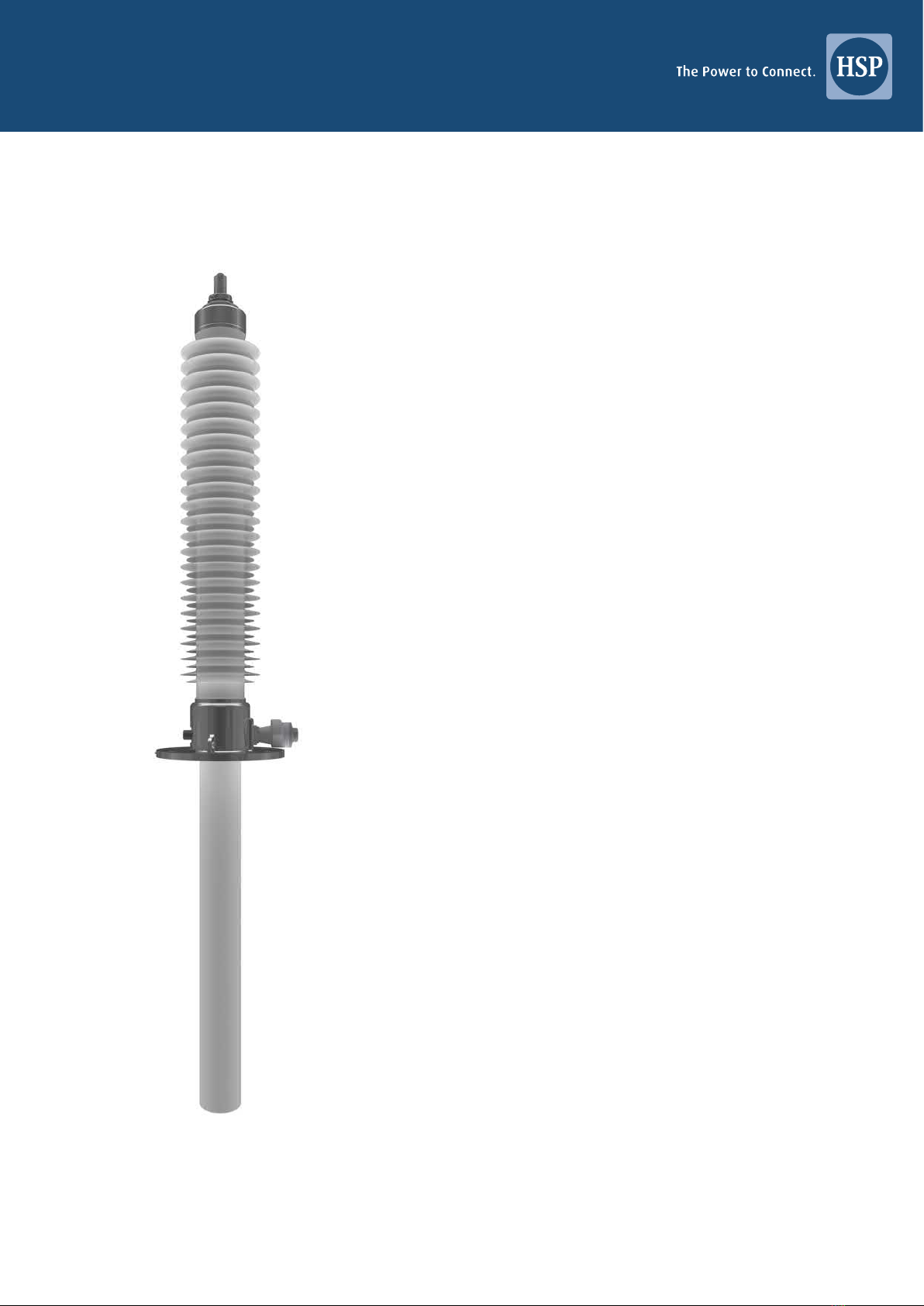
Range STARIS®-Sia+ 3/53