Max Blank Erfurt User manual

Erfurt
Erfurt SP
ASSEMBLY INSTRUCTIONS
Type plate for your heater
Please see the next page for further
important notes!

Page 2
Affixing the type plate
It is now a legal requirement to affix the enclosed type plate to your
heater. The chimney sweep needs to see the specifications on the
heater to be able to approve the device.
You can therefore decide where to affix the type plate in your given
installation so that it is clearly legible with the chosen location complementing
the stove's overall appearance.
How to affix the type plate:
1. Remove the type plate from the envelope.
2. Affix the plate to an obvious place on the device; depending on your
installation type, choose the bottom part of the stove where it is not too
hot.
Our recommendation:
a) bottom part of the back wall
b) bottom part of the side panels
c) on the drawer
d) on the stone or steel board
3. Remove the adhesive backing and affix the plate to the designated place.
The type plate and the adhesive backing are heat-resistant up to approx.
180°C.
Serial number:
You can find the heater's serial number in the bottom part of
the combustion chamber when you have the door open.

Page 3
ASSEMBLY INSTRUCTIONS
FOR WOOD-BURNING STOVE
Model: Erfurt
Contents: Page
1Data Sheet 4
2Safety Distances 6
3 Further notes 7
4Air Slide Settings 8
5Assembling the Chamottes 9
6Cleaning 12
7Assembly 13
8Outside Air Connection 16
9Accessories 17
10 Scope of Delivery 17
11 Product data sheet 18
Subject to technical changes.
Please read your technical instructions as well as the enclosed installation and
operating instructions carefully and keep them in a safe place.
Follow national and European standards and applicable to local provisions.

Page 4
1 Data Sheet (Dimensions in cm)
The following standards and requirements are fulfilled
EN 13240
1. BImSchV Stufe 2
Austria Art. 15a B-VG
BStV Munich
BStV Regensburg
FBStVO Aachen
Switzerland LRV 2011
VKF-Nr. 26909
Denmark
Page 5
Specifications
Erfurt
Erfurt SP
Height
135 cm
166 cm
Width (body)
30 cm
30 cm
Depth (body)
30 cm
30 cm
Total weight (incl. accumulator)
120 kg
169 kg
Chamottes weight
14 kg
14 kg
Heat accumulator weight
-
39 kg
Flue pipe socket
Ø 150 mm
Ø 150 mm
Outside air connection
Ø 100 mm
Ø 100 mm
Combustion chamber width
25,5 cm
25,5 cm
Combustion chamber depth
25,5 cm
25,5 cm
Combustion chamber height
52 cm
52 cm
Fire door height
66 cm
66 cm
Fire door width
42 cm
42 cm
Door glass height
54 cm
54 cm
Door glass width
34 cm
34 cm
Test values according to
DIN EN 13240
Intermittent burning stove
Permissible fuel
Split logs, wood briquettes1)
Nominal heat output
5,9 kW
7,2 kW
Room heat output
5,9 kW
7,2 kW
Amount of fuel
1,9 kg/h
2,3 kg/h
Efficiency
78 %
80 %
CO (13%O2)
1202,1 mg/m³
1062,8 mg/m³
CO (13%O2)
0,096 %
0,085 %
Dust (13%O2)
35,2 mg/m³
28,8 mg/m³
NOx(13%O2)
93,3 mg/m³
107,1 mg/m³
OGC (CxHy) (13%O2)
86,7 mg/m³
71,0 mg/m³
Room heat capacity
70-210 m³
70-210 m³
Data for chimney calculation according to EN 13384
Flue gas mass flow
8,92 g/s
8,81 g/s
Flue gas temperature on pipe socket
220 °C
248 °C
Minimum draught
12 Pa
12 Pa
provided the heater has a 1,0 m pipe section
All the above details are test bench values
Details on room heat capacity may differ depending on your place of use
1) Only wood briquettes according to standard EN DIN EN ISO 17225-3, quality class A1 approved
Subject to technical changes

Page 6
2 Safety Distances
Protect all flammable components, furniture, or objects near the wood-burning stove from
heat exposure. In particular, follow applicable local regulations.
Safety distance to flammable components:
The radiant heat (2) from the door glass must maintain a distance of 80 cm to flammable
components.
Lateral and rear distance to flammable walls is at least 50 cm.
If you insulate the wall to be protected using 4 cm of material (3), such as a
vermiculite board (e.g. with Promasil 950 KS plate) or similar insulation, the lateral and
rear distances are at least 21 cm.
In case of a flammable floor, protect it using a fire protection board (1); dimensions starting
from firebox opening: at least 30 cm on the sides, and at least 50 cm to the front.
Follow local provisions when choosing the fire protection board.
1. Fire protection board
2. Radiant heat
3. Vermiculite board or similar
Distance to insulated wall
Distance to flammable wall

Page 7
3 Further notes
Maintaining the safety distances to flammable components and those requiring protection
means you are complying with document J of the building regulations, regulating the rules
for installing solid fuel appliances. If the components are non-flammable, you can reduce
the distance. Despite maintaining the above safety distances, sensitive wall materials may
stain; this, however, is no basis for a warranty claim.
Your wood-burning stove is an intermittent burning stove (burning for a limited period of
time). Therefore, do not overwork it significantly or permanently.
In normal operating conditions, the wood-burning stove's door handle remains cool.
In case it becomes too hot, use a protective glove.
The minimum draught is 12Pa. The maximum draught is 15Pa.
If the negative pressure exceeds 15Pa, limit the draught.
For the outside air connection, you need to take into account that the atmospheric air
pressure is the same as the ambient air pressure. Excessive or insufficient draught may
affect the combustion result.
Check the heat-resistant door magnets at least once a year for proper adjustment and
readjust them, if necessary, to ensure the firebox door closes tightly.
Check the door magnets for damage (e.g., tears, fissures) at least once a year and replace
them, if necessary, through your specialist retailer.
The gaskets on the firebox doors and their glass are under thermal strain and may be
subject to wear and tear. Therefore, check the gaskets periodically and replace them once
a year.

Page 8
4 Air Slide Settings
Before heating the stove, please check
that the ash container (4) and the base
(2) are in place. If pellet box (3) is
existing, this box can also be optionally
installed.
The air slide (1) regulates how much air
is available for combustion.
The air slide (1) is a lever (1) for
regulating the flow of primary air (5) and
secondary air (6).
To burn approx. 1,5 / 1,8 kg (approx. 2 /
3 split logs with a length of 20 to 25 cm)
of fuel (7) takes approx. 40 to 45 min
depending on fuel quality, chimney, and
weather conditions.
When the fuel has burned down and
created a basic firebed, you can add
more fuel.
Whilst the stove warms up, move the air
slide into the left-most position (1) as
per the arrow symbol.
Combustion air fully open
Air slide middle:
In this position the system reaches
its nominal load
Air slide (1) in right-most position:
Combustion air fully closed
6
7
0
0
5
1
1
1
0
0
1
4
3
2
1
0
0

Page 9
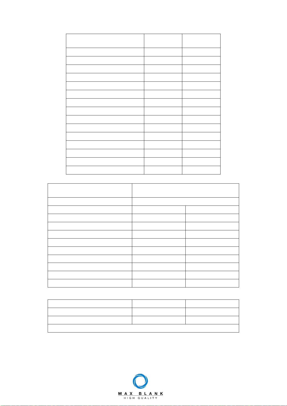
5 Assembling the Chamottes
Insert the chamotte pieces dry, do not use fixatives. Insert the individual chamotte stones
in the correct order into the combustion chamber as described below. Ensure the
chamottes sit properly so your stove works flawlessly.
Check the chamotte stones and
deflection plates for completeness.
The lining of combustion chamber
consists the following parts:
- 1x upper deflection plate (1)
- 1x lower deflection plate (2)
- 2x left side plate (3)
- 2x right side plate (4)
Place chamotte stones and deflection
plates next to the wood-burning stove.
Check the floor of the combustion
chamber for contamination and clean
it, if necessary.
Safe the fire door (5) by
swinging up the door arrester
(6) against automatic closing.
Insert the left side stone (3) and the
right side stone (4) into the firebox (7)
as illustrated.
2
4
4
3
4
3
1
3
7
6
5
3
4

Page 10
Place another left (3) and right (4) side
stone on the already installed side
stones.
Install the top deflection plate (1) as
illustrated.
Place the top deflection plate (1) onto
the top contact surface (O) and the
back mounting bracket (U) as
illustrated.
Insert the lower deflector plate (2) into
the firebox as illustrated, place it on
the side supports (7) on the front and
on the side plates (3,4) on the back.
O
4
2
U
4
3
3
1
1
1

Page 11
The lower deflector plate (2) have to
be rest on the top shelf (O) as
illustrated and on the side plates (3,4)
with the loop (U) on the back.
Push the deflector plate (2) back until
it is positioned with the loop (7).
Insert the ash container (9) into the
combustion chamber.
Put the adapter ring (8) into the
combustion chamber floor (10).
Insert the Firedog (11).
Insert the base (12) into the adapter
ring (8).
If the option of burnig pellet is
possible, please insert the
corresponding pellet box (13) in to the
adapter ring (8) before puting inside
the base (12).
Uninstall the chamottes
in reverse order.
11
O
U
8
10
9
7
2
12
13
8
3,4

Page 12
6 Cleaning
To clean the firebox thoroughly, you can uninstall the chamotte cladding in the reverse
order to that described in Section 5. This gives you even better access to the firebox and
the combustion air openings.
To clean the flue gas pipes, remove the baffles from the wood-burning stove to enable you
to remove soot from the flue gas pipes in the combustion chamber.
To clean the stove pipes, remove
both baffles (1) and (2).
This gives you free access to the
flue pipe socket.
To empty the ash container (9)
remove the base (12) and the
adapter ring (8) from the firebox.
Remove the inspection cover (14).
Clean the air ducts with a suitable
vacuum cleaner.
1
2
12
8
9
14

Page 13
7 Assembly: Erfurt wood-burning stove
Caution!
Handle all cladding elements with extreme care!
Ensure not to collide with other parts or objects!
Do not position cladding elements on corners or edges!
Place the parts on a soft surface (e.g., cardboard)!
Tools for assembling the stove:
Spirit level
Spanner AF13
Spanner AF10
Carefully take the wood-burning stove
(1) out of its transport frame.
Remove the steel cover (2) from the
wood-burning stove (1)
Outside air
2
Steel cover
Firebox door
1
Accumulation Block
Base

Page 14
Place the wood-burning stove (1) in its
final location and check its horizontal
position using a spirit level.
If necessary, use the adjustable feet
(3) for aligning the stove.
Use the spanner for turning the
adjustable feet (3).
Place the steel cover (2) onto the
wood-burning stove (1).
Adjust the height position of the steel
cover (2) with the adjusting nuts (4) on
the underside of the steel cover (2).
2
1
3
4
3
1
Page 15
Installing the accumulator stones
at Erfurt SP
To install the accumulator stones
blocks, remove the cover (2).
The complete accumulation block
consists of 4 identical accumulator
stones (5).
The accumulator stones (5) have to be
placed with the radial groove down in
the stove (1).
The adjacent figure shows the built-in
accumulator stones in the Erfurt SP
with flue pipe connection to the top (6).
Place the steel cover (2) onto the
wood-burning stove (1).
Adjust the height position of the steel
cover (2) with the adjusting nuts (4) on
the underside of the steel cover (2).
See Section 5 for assembling the
chamottes.
1
2
4
5
5
5
1
6

Page 16
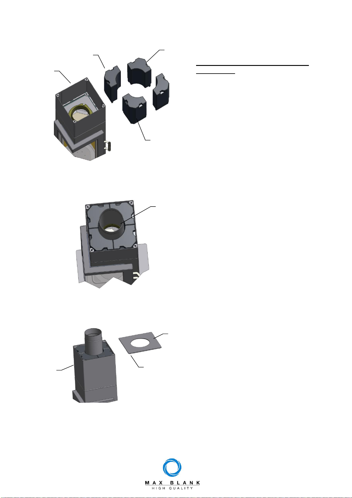
8 Outside Air Connection
Outside air connection
The wood-burning stove is prepared
for an external air connection to the
rear (H) or bottom (U).
Depending on your connection type,
(downwards (U) or backwards (H)),
use a straight outside air pipe socket
(1) or an angled outside air pipe socket
(2).
Depending on the wood-burning stove
design you may need to apply
prepared apertures or install custom
components.
2
H
1
U

Page 17
9 Accessories
Floor protectors
The Max Blank floor protectors are a
practical solution to protect the floor to
the side and in front of the stove.
The floor protectors can be removed
for cleaning and when stove is not
burning.
10 Scope of Delivery
- Erfurt wood-burning stove
- Lining of the Combustion chamber
- Installation and operating instructions
- Assembly instructions with type plate

Page 18
11 Product data sheet
Name or trademark
Max Blank GmbH
Klaus-Blank-Straße 1
D-91747 Westheim
Model identifier
KO9 (Erfurt, Erfurt SP)
Energy efficiency class
A
Direct heat output
7,2 kW
Indirect heat output
(indicate if applicable)
N.A.
Energy efficiency index (EEI)
106,0
Fuel energy efficiency at
nominal heat output
80,0 %
and optionally
Fuel energy efficiency at
minimum load
N.A.
Notes on special
arrangements for assembly,
installation or maintenance
of the individual room heater
- The fire protection and safety distances among
other combustible materials have to be strictly
adhered to!
- The fireplace must always be able to supply
sufficient combustion air. Air-exhaust systems
can disturb the combustion air supply!

Page 19
Notes:

Erfurt-ENG-04.docx
If you require customer service, please contact your specialist
retailer
(see manufacturer's stamp)
Max Blank GmbH - Klaus-Blank-Straße 1 - D-91747 Westheim
Subject to errors, changes in construction, design, colour hues, delivery scope, and typographical errors.
This manual suits for next models
1
Table of contents
Popular Wood Stove manuals by other brands


FRANCO BELGE
FRANCO BELGE SAVOIE 134 08 03 Technical manual

Ravelli
Ravelli DUAL 9 SUPER Use and maintenance manual

FRANCO BELGE
FRANCO BELGE 134 05 02 Technical manual

Tulikivi
Tulikivi TU 1000/4 Series Construction drawings

Breckwell
Breckwell Luxury P2000I owner's manual

England's Stove Works
England's Stove Works 55-TRPCB120 Installation & operation manual

Jøtul
Jøtul F 135 Installation and operating instructions

Lopi
Lopi M-520 owner's manual

Vermont Castings
Vermont Castings BR36 Homeowner's installation and operating manual

ROBENS
ROBENS 690244 instruction manual

United States Stove
United States Stove Forester US2000E manual

Firebelly
Firebelly T1 Operating & installation instructions